Inotech IT3001 User manual
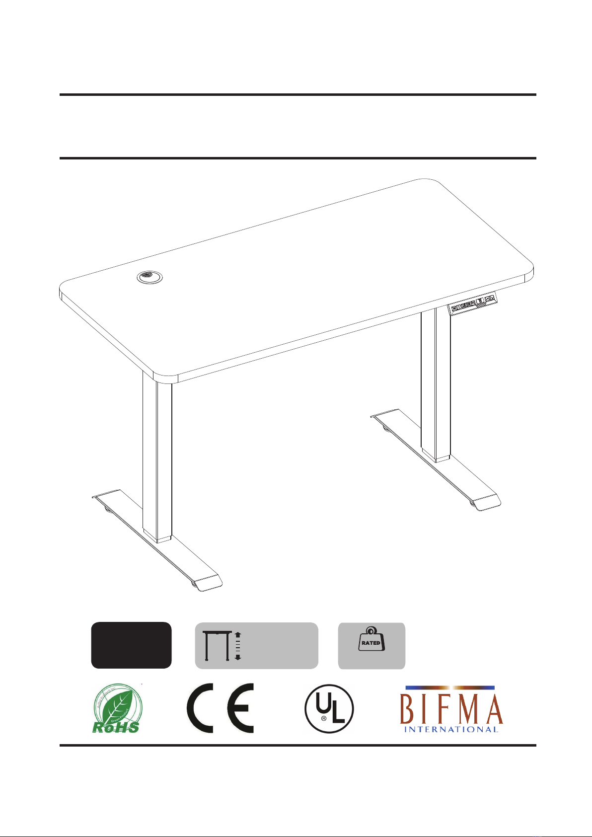
Electric Height Adjustable Standing Desk
Dual Motor
Color: Black Desktop + Black Frame
Instruction Manual
IT3001
IT3001
min 27.6 inch
max 47.2 inch
V1.0
100 kg/ 220 lbs

01
Safety Instructions ---------------------------------------------------------------------------- Page 2
Package Contents ---------------------------------------------------------------------------- Page 3
Assembly Steps ------------------------------------------------------------------------------- Page 4~10
Step 1-2 ----------------------------------------------------------------------------------- Page 4
Step 3-5 ----------------------------------------------------------------------------------- Page 5
Step 6-8 ----------------------------------------------------------------------------------- Page 6
Step 9-10 --------------------------------------------------------------------------------- Page 7
Step 11-12 ------------------------------------------------------------------------------- Page 8
Step 13-14 ------------------------------------------------------------------------------- Page 9
Step 15 ----------------------------------------------------------------------------------- Page 10
Cautions ---------------------------------------------------------------------------------------- Page 10
Operation Guide ------------------------------------------------------------------------------ Page 11~12
Error Code ------------------------------------------------------------------------------------- Page 12
Product Dimensions ------------------------------------------------------------------------- Page 13
Technical Specifications -------------------------------------------------------------------- Page 13
CONTENTS

SAFETY INSTRUCTIONS
02
BEFORE ASSEMBLY
Put a mat on the flat or level floor to avoid product scratches.
Layout all components and hardware. Verify all parts are included and undamaged.
Should anybody intends to install or use this electric height adjustable desk,
please read and understand this manual carefully.
Do not use this product for any purpose that is not explicitly specified in this manual.
Do not exceed weight capacity.
Indoor use only.
We cannot be liable for damage or injury caused by incorrect assembly or inappropriate use.
The product must be connected to the correct power supply.
Keep dry for the product, especially for the power and system part to avoid electric failure.
WARNING
Do not open or modify any components, including the legs, system control box or adjustment
controller. This might cause electric shock or permanent damage to the product.
This product contains small items that could be a choking hazard if swallowed. KEEP AWAY
FROM CHILDREN UNDER 3 YEARS OLD. ADULT SUPERVISION IS REQUIRED.
Neither adults nor children can sit or stand on the desk. Do not play within the area under
the desk. This might cause to severe bodily injury.
Before using the product for the first time, initialize the desk by resetting the adjustment
controller. Refer to the user guide of controller (Page 11).
If you do not understand these instructions or have any doubt about the safety instructions,
USE & LIABILITY
This product is powered by electricity. In order to avoid burns, fire and electric shock, please
read the following instructions carefully.
ELECTRICAL SAFETY
DO NOT EXCEED WEIGHT CAPACITY.
220 lbs
(100 kg)
DO NOT place hands on or near support bars. Moving parts can crush and
cut.Pinch points are created during lifting and lowering the worksurface.
Failure to follow these instructions may result in serious personal injury.
WARNING
PINCH POINT

PACKAGE CONTENTS
03
(x2)
Lift Column
(x1)
2
Crossbar End
(x4)
(x8)
4
Leveling Stud
(x1)
7
Power Adapter
Power Wire
(x1)
8
Handset
Headphone Hook Socket Tray Hook
Socket Tray
9
(x1)
12
(x1)
10 (x2)
11
(x1)
Tabletop
(x1)
6
Control Box
(x2)
3
Base
(x2)
5
Side Bracket
A
M6x12mm
(x6)
C
M6x8mm
(x2)
D
M4x12mm
(x4)
F
M5x18mm
(x16)
B
M6x16mm
(x4)
E
M4x6mm
(x3)
G
Cable Clip
(x6)
H
Silicone Pad
(x1)
I
3mm Allen Key
(x1)
J
4mm Allen Key
Phillips Screw Driver
(Not Included)
Electric Drill
(Not Included)
Accessory Kit
Tools Needed
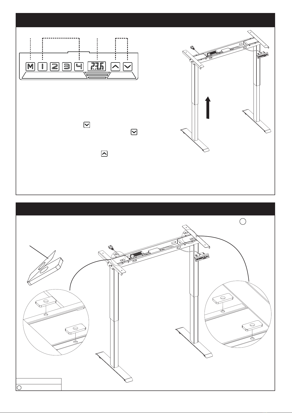
ASSEMBLY STEPS
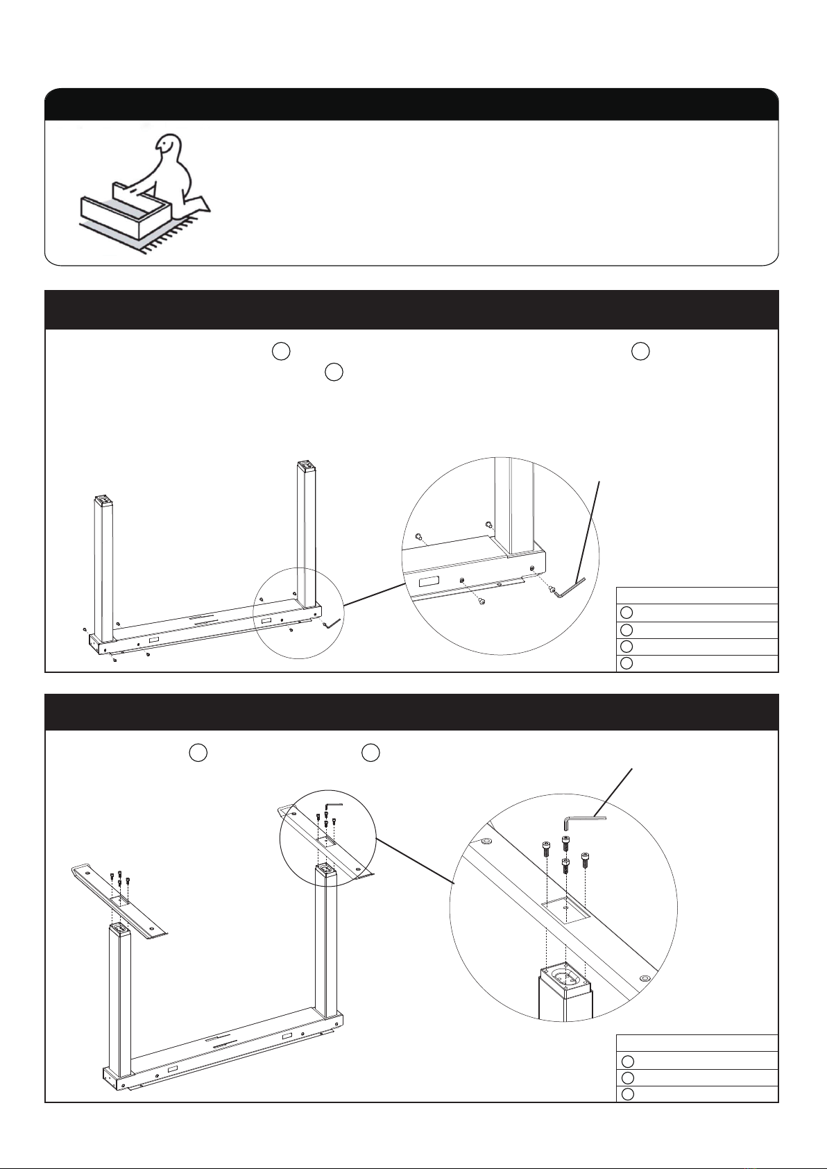
STEP 1
STEP 2
J
04
Lay a mat or old blanket out to assemble onto so the floor and
the furniture doesn’t get scratched or damaged during building.
Lay down the Crossbar End at a level floor, connect the two Lift Columns to the left
and right side of the Crossbar End by using the Screws(A). Then tighten the Screws with
the 4mm Alley Key(J).
Reminder: Hide the cables on both lift columns into the crossbar end to avoid cable or
power damage.
2
2
1
Attach the Bases on the Lift Columns by Screws( B ).
Then tighten the Screws( B ) with the 4mm Allen Key( J ).
13
Bases x2
M6x16mm Screws x8
4mm Allen Key x1
3
B
J
Checklist
Lift Column x2
Crossbar End x2
M6x12mm Screws x8
4mm Allen Key x1
2
1
A
J
Installation Tips
J
Checklist
J
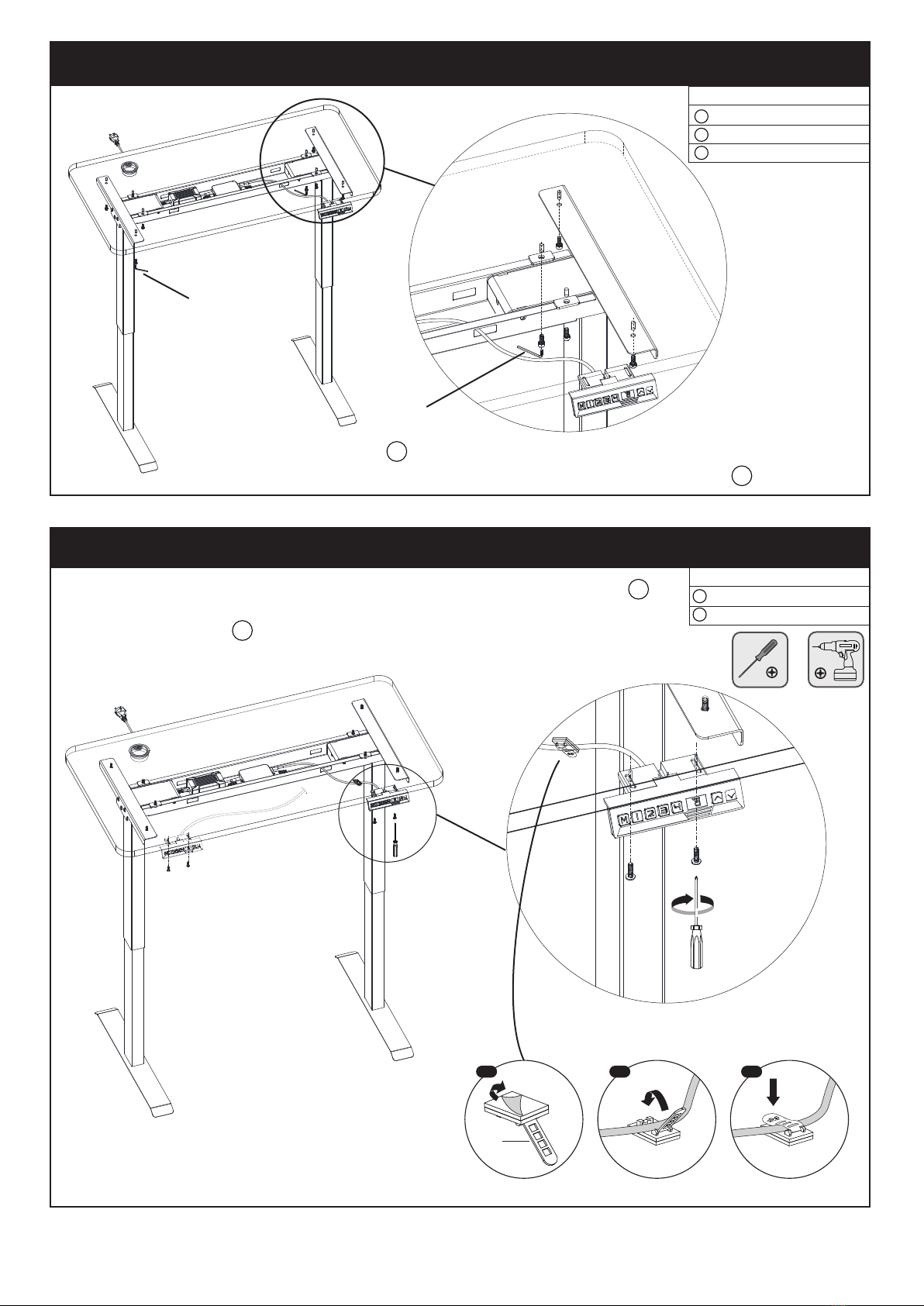
STEP 3
STEP 4
05
First, remove the protective film on the Leveling Studs .
Then tighten them into the Bases by hand.
Remove the Protective Film
4
4
3
Attach the Side Brackets on the Lift Columns by Screws( C ).
Then tighten the Screws( C ) with the 4mm Allen Key( J ).
Turn over the frame to stay upwards.
15
STEP 5
Put the Control Box into the Crossbar End ,and adhere to the punched hole ,
push it and make it firm.
Note: Control Box is equipped with
gyro sensor so the table and
control box must be leveled.
26
Side Brackets x2
M6x8mm Screws x6
4mm Allen Key x1
5
C
Leveling Studs x4
4
Control Box x1
6
Checklist
Checklist
Checklist
J
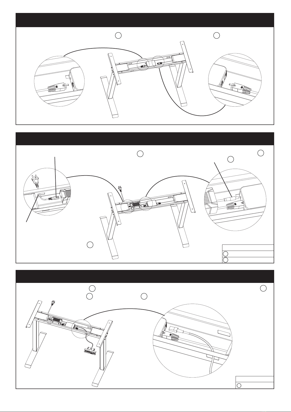
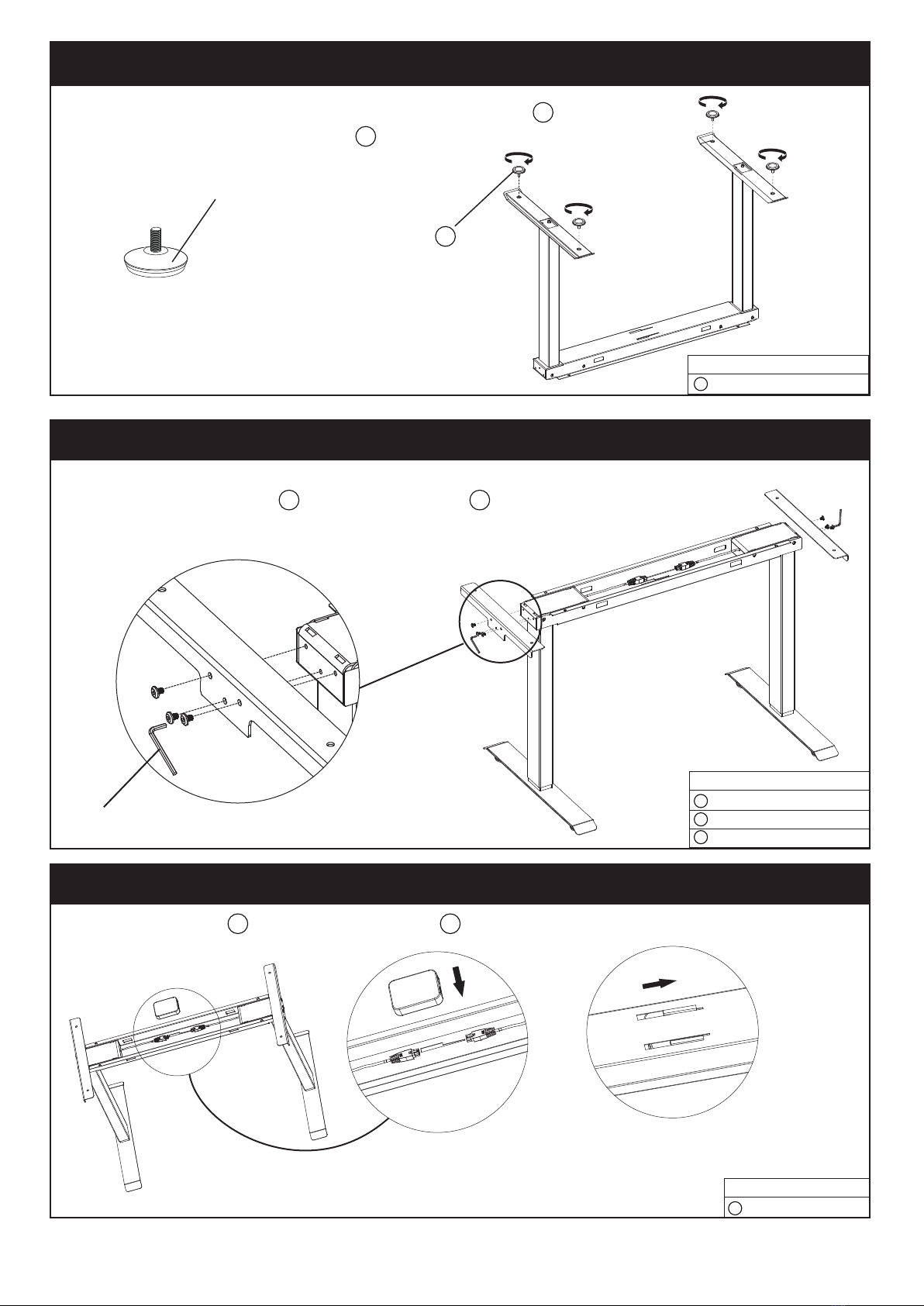
STEP 6
STEP 7
06
Insert the plug of the Lift Columns into the socket of the Control Box
6
1
7
2
6
7
STEP 8
2
6
8
Connect the Power Wire to the Power Adapter .
Note: the other end of the
Power Wire must be passed
through one of the four punched
holes on the Crossbar End .
Connect the Power Adapter to
the Control Box .
Let the plug of the Handset pass through one of the four punched holes on the Crossbar End .
Then connect the Handset to the Control Box .
8
Checklist
Power Adapter x1
Power Wire x1
7
7
Handset x1
8
Checklist
First, remove the film on the Silicone Pad ( H ) .Then glue it on the Crossbar End .
Remove the Film
STEP 9 Testing Before Final Assembly
07
STEP 10
2
Setting Four Memory Height Desk Height Up and Down
Before attaching the tabletop to the frame, make sure that
- The lift columns are level and set at the lowest position.
-All the screws are tightened to avoid the desk making noise
and wobbling.
A
Note: make sure the hole on each Silicone Pad is
perfectly matched with each hole on the Crossbar End.
Two extra Silicone Pads are provided in case of any
missed or damage part of the pads.
Note: if you run the desk up and down for two times or more than 2 minutes, it may get to overheating
protection, the handset displays “HOT”. please wait about 18 minutes until the motors
will be cool down. Afterwards, the desk can run again.
Please read the page 11 for more operation guide for the handset.
ctivate the desk by following the next steps.
-Connect the Power Wire to electricity to get the desk power on.
-Press the button “DOWN” to the lowest position.
-Release the button then your desk is ready to use.
-Reset the desk by pressing the button “DOWN” and hold up for
5-10 seconds until the buzzer reminds by sounding ‘bee’.
-Press and hold the button “UP” to raise the desk to its highest position.
-Unplug the Power Wire after adjusting the desk to its highest position and continue to next assembly step.
Silicone Pad x4
H
Checklist
Easily put the Tabletop on the frame, make sure it will not fall down.
Using the Screws(B) and 4mm Alley Key(J) to tighten the Tabletop to the frame.
There are two pilot holes in both left and right side of the Tabletop
underside. Choose either side according to your own preference.
Attach the Handset to align with the chosen pilot holes. Then attach
and tighten screws (D) with a screwdriver or electric drill.
Once Handset is installed, cable clips (G) can
be attached to the desk for cable management.
STEP 11
08
STEP 12
9
9
1 2 3
G
9
8
J
J
M4x12mm Screws x2
Cable Clips x3
D
G
Tabletop x1
M6x16mm Screws x8
4mm Allen Key x1
9
B
J
Checklist
Checklist
Attach Socket tray Hooks in the Socket tray by Screws( E ).
Then tighten the Screws( E ) with the 3mm Allen Key( I ).
Attach the Socket tray under the Tabletop by Screws( F ) .
Then tighten the Screws( F ) with a screwdriver or electric drill.
STEP 13
09
STEP 14
11 12
12 9
Attach the Headphone Hook under the Tabletop by Screws( F ) .
Then tighten the Screws( F ) with the screwdriver.
Note: the Headphone Hook is available
to attach at any place under the tabletop
freely as you prefer.
10 9
Socket tray Hook x2
Socket tray x1
M4x6mm Screws x4
3mm Allen Key x1
11
12
E
I
Headphone Hook x1
M5x18mm Screws x4
10
F
Checklist
I
Checklist

CAUTION!
Failure to follow these instructions may result in property damage and/or personal injury.
Do not exceed desk weight limit. Keep area of vertical motion free of
obstacles.
Keep weight on desk balanced for
correct operation and longer life of
components.
Leave enough slack in cables to allow for
full range of vertical motion.
Plug in the power wire to get the desk power on. Just get started by pressing the handset to enjoy
your life with our smart height adjustable desk.
STEP 15
10
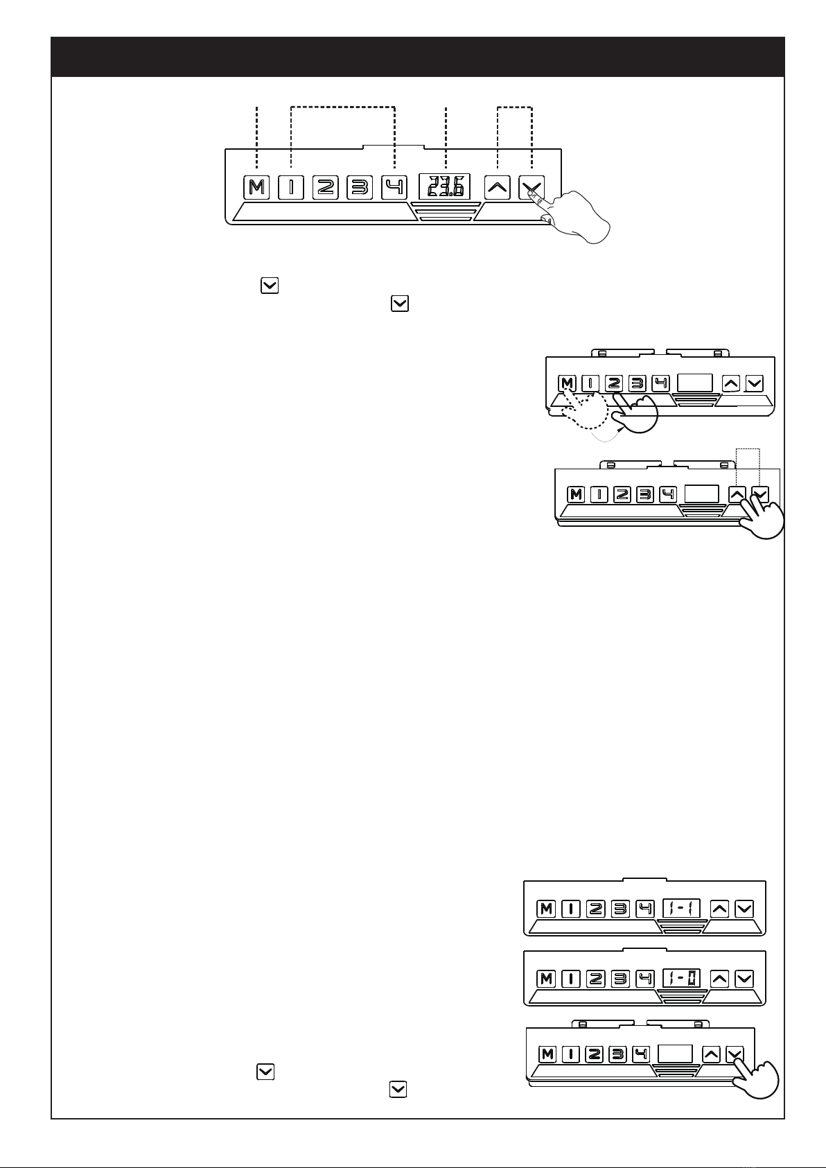
Operation Guide
11
Setting Four Memory Height Desk Height Up and Down
28.5
Press by holding 5-10 seconds
RST
LOC
1. Memorize your desired height
Activate the desk by following the next steps.
-Connect the Power Wire to electricity to get the desk power on.
-Press the button “DOWN” to the lowest position.
-Release the button then your desk is ready to use.
-Press “UP” or “DOWN” button until your desired height.
-Press “M” and release, the handset will display “S-”.
-Choose number 1-4, the desk will memory the height of this position.
2. Advanced Safety feature-lock and unlock the table.
-Press “UP” and “DOWN” button at same time for 5 seconds,display “LOC”.
-All single button will be inactive and table will be unable to move.
-Pressing “UP” and “DOWN” button together will unlock the key pad
and release the “LOC”.
3. Set the limited lowest height
-Press “DOWN” button until your desired height.
-Press and hold “M” + “DOWN” for 5 seconds until the buzzer reminds by
sounding ”bee”. Now the lowest height is limited as you desired.
-To cancel the limitation, press and hold “M” + “DOWN” for 5 seconds
again until the buzzer reminds by sounding ”bee”.
4. Set the limited highest height
-Press “UP” button until your desired height.
-Press and hold “M” + “UP” for 5 seconds until the buzzer reminds by
sounding ”bee”. Now the highest height is limited as you desired.
-To cancel the limitation, press and hold “M” + “UP” for 5 seconds
again until the buzzer reminds by sounding ”bee”.
5. Anti-collision Detection
-When the desk crashes something from the bottom, or get sudden
force from the top, the desk will move to opposite direction and stop
running. It will prevent from product damage and injury.
6. Switch The Display Mode From INCH to CENTIMETER
-Long press the button "M" on the handset for 10-15 seconds until
it displays and flickers "1 - 1".
-Press the button "UP" or "DOWN" and adjust to "1 - 0".
-Long press the button "M" again until it displays the normal height.
Then release the button.
NOTE: "1 - 1" refers to INCH display mode.
"1 - 0" refers to CENTIMETER display mode.
7. Reset the table
-When the handset displays “RST” , please reset the table.
-Press the button “DOWN” to the lowest position.
-Reset the desk by pressing the button “DOWN” and hold up
for 5-10 seconds until the buzzer reminds by sounding “bee”.
-Reset the desk by pressing the button “DOWN” and hold up for
5-10 seconds until the buzzer reminds by sounding ‘bee’.

12
Error Code
Operation Guide
8. Error code
-When the handset displays Error Code, please refer to below Error code sheet.
-If the error is not yet resolved, unplug the Power Wire and wait for 30 seconds. Then plug back the Power Wire
and reset the desk again (refer to “7. Reset the table”).
9. If the handset displays HOT, please wait about 18 minutes until the motors will be cool down.
Afterwards, the desk can run again.
E1 Main power is too high Check the main power
E2 Screw clearance over 1cm Ini�aliza�on
E3 Hand Controller not connected Wai�ng for the system sleep
E4 Hand Controller communica�on error Check hand controller line
E6 Main power start error Change controller box
E7 Main power run protect Reconnect controller power
E8 The table �lts when it is running Reset
E09/Hot Main power overhea�ng protection Wait 18mins un�l motors are cool down
E11 Motor1 no connect Check motor line
E12 Motor1 Current sampling error Change controller box
E13 Motor1 lose phase line Check motor line
E14 Motor1 Hall error Check the hall or hall line
E15 Motor1 phase short Change motor
E16 Motor1 blocked Ini�aliza�on
E17 Motor1 direc�on error Lines to change the motor or hall
E18 Motor1 over loading Reduce the loading
E21 Motor2 no connect Check motor line
E22 Motor2 Current sampling error Change controller box
E23 Motor2 lose phase line Check motor line
E24 Motor2 Hall error Check the hall or hall line
E25 Motor2 phase short Change motor
E26 Motor2 blocked Ini�aliza�on
E27 Motor2 direc�on error Lines to change the motor or hall
E28 Motor2 over loading Reduce the loading
E40 Tandem line drops Check the tandem line
E41 Tandem signal error Check the tandem line or change box
E42 EEPROM error change box
E43 Gyro-sensor error change box
InstructionsError Code Solutions

13
Product Dimensions
120 cm / 47.2 in
96 cm / 37.8 in
2.5 cm / 0.98 in
60 cm / 23.6 in
70cm /27.6 in
120cm/47.2 in
~
60 cm / 23.6 in
Lowest Height 70cm(27.6in)
Highest Height 120cm(47.2in)
Weight Capacity 100Kg(220 lbs)
Tabletop Size 120cm(47.2in)x60cm(23.6in)x2.5cm(0.98in)
Input Voltage 100-240V
Travel Speed 30mm per second
Applicable Temperature 0~40
℃
Noise <50 db
Duty Cycle Continuous operation for 2 mins at most
after pause for 18 mins
Technical Specifications

CAUTION AND MAINTENANCE:
· Never allow children to climb, stand or play on any part of the desk.
· This product is intended for indoor use only. Using this product outdoors could lead
to product failure and personal injury.
· Contact our customer service team whenever you have any confusion or uncertainty
with the product.
If you have any question, please contact us.
14
Table of contents
Other Inotech Indoor Furnishing manuals

Popular Indoor Furnishing manuals by other brands

Regency
Regency LWMS3015 Assembly instructions

Furniture of America
Furniture of America CM7751C Assembly instructions

Safavieh Furniture
Safavieh Furniture Estella CNS5731 manual

PLACES OF STYLE
PLACES OF STYLE Ovalfuss Assembly instruction

Trasman
Trasman 1138 Bo1 Assembly manual

Costway
Costway JV10856 manual


