INOV8 F240 User manual

INOV8 Model F240 – Edited September 2008
i
INTERNATIONAL INCORPORATED
ASSEMBLY, INSTALLATION, MAINTENANCE
AND OPERATING INSTRUCTIONS
INOV8 F240 Multi-fueled Unit Heater & Furnace
Save These Instructions! This manual must be kept near the furnace!
Control No. 3120734

INOV8 Model F240 – Edited September 2008
ii
BL
SECTION 1 – GENERAL GUIDELINES...........................................................................................0
Codes & Regulations........................................................................................................................................................ 0
U.S. EPA Regulations & Used oil Burning........................................................................................................................ 0
Listing Agencies ............................................................................................................................................................... 1
Fuels- general information................................................................................................................................................ 1
Special Precautions!......................................................................................................................................................... 1
Warranty is void if … ........................................................................................................................................................ 2
Disposal............................................................................................................................................................................ 2
Unpacking & Inspecting.................................................................................................................................................... 2
Minimum Clearances........................................................................................................................................................ 2
Shipping & parts information ............................................................................................................................................ 3
Figure 1 - Model F240 Dimensions .......................................................................................................................... 4
SECTION 2 – FURNACE INSTALLATION ......................................................................................5
FURNACE LOCATION ................................................................................................................................................ 5
ATTACHING THE BURNER TO THE FURNACE............................................................................................................... 5
Installing the Burner:......................................................................................................................................................... 5
Installing the Electrical Plug.............................................................................................................................................. 6
Electrical Hookup of the Furnace...................................................................................................................................... 6
Attaching the Air Connection ............................................................................................................................................ 7
Attaching the Oil Delivery Line (‘A’ in photo)..................................................................................................................... 6
Attaching the Return Line (‘B’ in photo) ............................................................................................................................ 6
Blocked Vent Switch –supplied with Canadian Furnaces (or optional) ............................................................................. 7
INSTALLATION DETAILS............................................................................................................................................. 7
Air Supply Installation ....................................................................................................................................................... 7
Chimney Installation ......................................................................................................................................................... 8
Installing the Barometric Draft Control.............................................................................................................................. 9
Draft Measurements & Adjustments............................................................................................................................... 10
Installing an Optional Draft Inducer ................................................................................................................................ 10
Installing an Optional Sealed Combustion System ......................................................................................................... 10
Figure 2 - Typical Installation Diagram (without bench tank).................................................................................. 12
Ceiling Mount Installation Considerations....................................................................................................................... 12
Electrical Supply Installation........................................................................................................................................... 12
Fan/Limit control............................................................................................................................................................. 13
TANK &PIPING CONSIDERATIONS........................................................................................................................... 13
Oil Storage Considerations............................................................................................................................................. 13
Additional Oil Storage Consideration.............................................................................................................................. 13
Piping & Fitting Recommendations................................................................................................................................. 13
Tank Filter ...................................................................................................................................................................... 14
Vapor Eliminator Filter / Pressure Relief Assembly ........................................................................................................ 14
Installation of Vent Line from Vapor Eliminator back to the Tank ................................................................................... 14
Vapor Eliminator Filter .................................................................................................................................................... 14
Bench Tank Installation .................................................................................................................................................. 16
Figure 3 - Bench Tank Setup ................................................................................................................................. 16
Boost Pump (optional) .................................................................................................................................................... 18
Figure 4 - Diagram Showing Installation of Suntec Boost Pump, Filter, Check valve, Regulator & Gauges .......... 19
Figure 5 – Burner Diagram .................................................................................................................................... 20
Final Installation Checklist .............................................................................................................................................. 21
SECTION 3 – OPERATING THE FURNACE .................................................................................22
FIRST START-UP OF FURNACE................................................................................................................................22
Priming the Oil System ................................................................................................................................................... 22
Firing up the Furnace the First Time .............................................................................................................................. 22
Ducted Furnace Installation Check (Model F240 SC)..................................................................................................... 23
NORMAL OPERATION OF FURNACE .........................................................................................................................24
FACTORY SETTINGS...............................................................................................................................................25
Figure 6 - Electrode Adjustment Diagram .............................................................................................................. 25
FLAME ADJUSTMENTS ............................................................................................................................................26
Figure 7 – Proper & Improper Flame appearances............................................................................................... 26
MAINTENANCE .......................................................................................................................................................27

INOV8 Model F240 – Edited September 2008 iii
General Information ........................................................................................................................................................ 27
Changing Filters.............................................................................................................................................................. 27
Vacuuming the Combustion Chamber & Heat Exchanger Tubes ................................................................................... 27
Annual Maintenance ....................................................................................................................................................... 28
Chimney Inspection ........................................................................................................................................................ 29
Summer Burner Refurbishing Program........................................................................................................................... 29
SECTION 4 - TROUBLESHOOTING ............................................................................................. 30
General Failure Categories & Potential Causes ............................................................................................................. 30
Using Lights on the Controller to Diagnose Symptoms................................................................................................... 31
SECTION 5 –DETAILED SERVICING PROCEDURES ................................................................. 33
Removing the Module from the Burner ........................................................................................................................... 33
Replacing the Module into the Burner............................................................................................................................. 33
Flushing the Final Delivery.............................................................................................................................................. 33
Checking the Oil Spray ................................................................................................................................................... 34
Checking the Oil System................................................................................................................................................. 34
Checking the Ignition Arc................................................................................................................................................ 35
Checking the Atomizing Air System................................................................................................................................ 35
Checking the Draft & things that can cause it to be wrong.............................................................................................. 36
By-passing the Bimba Cylinder....................................................................................................................................... 36
Replacing the Vapor Eliminator Filter ............................................................................................................................. 37
Cleaning the Nozzle........................................................................................................................................................ 37
Rebuilding the Pump ...................................................................................................................................................... 38
Cleaning the Pump Internal Pressure Regulator............................................................................................................. 39
Oil Temperature Controller: Operation & Settings .......................................................................................................... 39
Oil Temperature & Pressure Settings..................................................................................................................... 40
Adjusting the Temperature Controller..................................................................................................................... 40
Removing Excess Oil from Combustion Chamber.......................................................................................................... 41
PROCEDURE FOR PARTS REPLACEMENT................................................................................................................. 41
ADDENDUM................................................................................................................................... 42
THEORY OF OPERATION......................................................................................................................................... 42
MAIN COMPONENTS &THEIR FUNCTIONS ............................................................................................................... 43
The Fireye Controller ...................................................................................................................................................... 43
The Oil System ............................................................................................................................................................... 44
The Primary (atomizing) Air System ............................................................................................................................... 45
ELECTRICAL DIAGRAMS ......................................................................................................................................... 46
Figure 8 – Basic Wiring Diagram for Furnace with Prop Fan ................................................................................. 46
Figure 9 – Basic Wiring Diagram – for 240v Squirrel Cage Blower ........................................................................ 47
Figure 10 – Burner Electrical Diagram for Prop Fan............................................................................................... 48
Figure 11 – Burner Electrical Diagram for 240v Squirrel Cage Blower................................................................... 49
PARTS LIST &TOOLS............................................................................................................................................. 50
SECTION 6 - GLOSSARY ............................................................................................................. 51
Notations Used in this Manual
RISK OF INJURY OR SYSTEM DAMAGE – Identifies a possible dangerous
situation that can lead to personal injury or physical damage.
NOTICE – This is a tip or notice for optimum use of equipment and
adjustment as well as useful information.

INOV8 Model F240 – Edited September 2008
0
SECTION 1–GENERAL GUIDELINES
Congratulations on your purchase of this INOV8 Multi-fueled Furnace. You have
selected the highest quality, precision-engineered piece of equipment available,
designed specifically to allow you to fully benefit from the used oils generated in your
business. INOV8 has not compromised in engineering this product for high efficiency,
safety, longevity, operating economy, and to allow you a maximum of fuel choices; all
while providing the highest standards of environmental considerations. This manual was
written for the novice technician with detailed instructions for the installation, start-up,
routine operation and maintenance of this furnace. If these instructions and pertinent
local regulations are followed closely you will be assured full satisfaction.
CODES ®ULATIONS
This manual covers installation, maintenance and service of the INOV8 model F240 unit
heater or F240 SC furnace. Both are referred to using the term “furnace” throughout this
manual that covers the installation of the chimney system, fuel storage and piping
connections and electrical work. All work shall be performed by a qualified contractor in
strict accordance with the requirements of state, provincial and local regulating agencies
and codes pertaining to oil-burning equipment installations. After start-up the owner or its
representative should be instructed about the furnace operation and be given this
manual. This equipment must be installed according to these national standards.
For furnace equipment: ANSI/NFPA # 31 – Standard for the Installation of Oil-
Burning Equipment – 2006 Edition, and in Canada to CSA
Standard B139.
For chimney installation: ANSI/NFPA # 211 – Standard for Chimneys, Fireplaces,
Vents, and Solid Fuel Burning Appliance, 2006 Edition
For oil storage installation: NFPA # 31 – Standard for the Installation of Oil-Burning
Equipment – 2006 Edition
For electrical installation: NFPA # 70 – National Electrical Code – 2005
Cleaning and routine maintenance must be carried out at least quarterly during
operation. This shall include an overall check of the heating system. There should be
periodic inspection of the combustion chamber for possible deterioration. Any
discrepancies must be corrected immediately.
NOTE: This manual is for reference only. The manual does NOT purport to address all
design, installation and safety considerations. It is the responsibility of the user of this
manual to determine the applicability and safety of each individual application and ensure
its compliance with local building codes.
U.S. EPA REGULATIONS &USED OIL BURNING
On August 12, 1992 the U.S. Environmental Protection Agency (EPA) announced that it
would not list nor classify as hazardous waste, used oil destined for recycling. They also
affirmed the long-standing regulatory exemption, which allows the operation of used oil-
fired furnaces. Under this exemption, used oil-fired furnaces may operate without a
regulation so long as the owner burns "on-specification used oil". Used oil exceeding
EPA designated levels of contaminants is classified as "off-specification used oil"
which means the owner must comply with three requirements: the heater does not
exceed 500,000 BTU per hour, it is vented to the outside, and burns oil generated on-site
or collected from do-it-yourself oil changers. After years of careful study the EPA
concluded that used oils that are recycled in this manner do not pose a substantial
present or potential hazard to human health or the environment so long as they are
managed properly. To this end, EPA's regulations are designed to provide safe and
environmentally sound used oil management practices.

INOV8 Model F240 – Edited September 2008 1
LISTING AGENCIES
This equipment is tested and listed by Intertek ETL Semko (ETL) - an internationally
recognized third party test agency to UL 296A - Standard for Safety for Waste Oil
Burning Air-Heating Appliances, Edition 2, Revision 2006/03/08 (the U.S. used oil
standard), and to CSA B140.0 General Requirements for Oil Burning Equipment General
Instruction No 2-4 (R1991) Rev: 1991/01/01and is listed with the European Economic
Community with a CE registration number 3884/97. The INOV8 tanks are also tested
and listed by ETL to UL 80 Standard for Steel Tanks for Oil-Burned Fuel.
FUELS-GENERAL INFORMATION
This product is approved to burn the following oils: crankcase oil, crankcase oil with up to
20% gasoline, fuel oils up to #6 heating oil, jet fuel, mineral spirits and transmission oil.
The following additional oils have been tested and passed combustion analysis
requirements but are not approved as fuels due to a lack of standards to define them:
used and crude vegetable oil, and biodiesel. DO NOT attempt to burn other liquids
without written authorization from INOV8 International, Inc. Only used oil generated on
the premises of the owner may be used in this equipment, unless written authorization is
obtained from the regulatory authority.
Caution – used oils may contain gasoline, heavy metallic compounds and foreign
materials. When burned, these compounds are emitted from or deposited within this
furnace and therefore care should be taken when storing these oils or when using,
cleaning and maintaining this equipment.
SPECIAL PRECAUTIONS!
1. This furnace is listed for commercial or industrial use only. It may not be used for
residential or any other unauthorized purpose.
2. All furnaces must be wired strictly in accordance with wiring diagram and
instructions in this manual.
3. Disconnect the power supply before making wiring connections to prevent
electrical shock and equipment damage.
4. Disconnect the power supply before cleaning the furnace.
5. Do not install furnace or chimney connector closer than 18 inches to combustible
materials in any direction, except the louver side of the furnace, which must be
unobstructed.
6. DO NOT add fluids with the classification of a hazardous waste, or fuels with
flash points below 100oF (such as gasoline) to your used oils. (Check your local
codes for restrictions.)
7. For your protection - DO NOT store or use gasoline or other flammable vapors
and liquids in the vicinity of this or any other appliance.
8. Canadian standards allow only used oil generated on the premises of the owner
to be used as fuel, unless permitted by the regulatory authority.
9. Venting - Failure to provide proper venting could result in death, serious injury,
and/or property damage. Units must be installed with a flue connection, draft
regulator and proper vent to the outside of the building. Safe operation of any
gravity vented heating equipment requires a properly operating vent system,
correct provision for combustion air, and regular maintenance and inspection.
10. Hazardous Atmosphere - The INOV8 products are not designed for use in
hazardous atmospheres containing flammable vapors or combustible dust, or
atmospheres containing chlorinated or halogenated hydrocarbons.

INOV8 Model F240 – Edited September 2008
2
WARRANTY IS VOID IF …
1. The heater is not installed in accordance with these instructions and applicable
codes and ordinances.
2. The wiring is not in accordance with drawings in this manual.
3. The Furnace or burner is not maintained in accordance with maintenance
requirements – particularly failure to clean the combustion chamber and heat
exchanger on a regular basis.
4. Other than specified fuel is burned.
5. Fuel input capacity is over the rated condition of maximum flow rate of 1.68 US
gallons or 7.63 liters per hour.
Note: Information on the Limited Warranty was sent along with the sales order.
DISPOSAL
Dispose of packaging in an environmentally responsible manner. Dispose of all heating
system components that have to be replaced at an authorized disposal site. Dispose of
ash in a responsible manner.
UNPACKING &INSPECTING
Immediately upon receipt, check the cabinet and burner for any damage that may have
occurred in shipment. If damage is found, INOV8 or the sales representative must be
notified within two days in order to process shipping damage claims. Prior to shipping, all
components were inspected and the burner test fired, so the burner will still have oil in it.
MINIMUM CLEARANCES
Furnaces must be installed so that the following clearances are provided for proper air
movement, service and distance from combustible materials. In addition to walls and
ceilings, combustibles include rags, paper, or any moveable combustibles like gasoline
or other flammable fluid.
Inches Millimeters Purpose
Cabinet Fan Motor: 6 152 air movement
Chimney connector (flue pipe): 18 457 combustible material
Above Furnace: 24 609 combustible material
Below Furnace: 4 101 combustible material
Burner side: 48 1,219 service access
Outlet Louver: Unobstructed air movement

INOV8 Model F240 – Edited September 2008 3
SHIPPING &PARTS INFORMATION
The INOV8 Waste Oil Furnace is shipped on a pallet with strapping and plastic wrap.
This includes the heat exchanger, fan, and fan motor (mounted and wired). The burner is
packed in a separate box that also contains other parts, based on the following list and
what was purchased. Immediately upon receipt of INOV8 products inspect all parts for
possible shipping damage or missing parts and report any problems within 48 hours.
Check for the items shown in the photos, that they are received:
1. Oil Pickup Assembly, includes these parts from the top down:
a. One ¾” check valve
b. 3/4 “ x 2” black nipple
c. One 90ostreet elbow
d. Filter mount
e. One 90ostreet elbow
f. One ¾” x 12” pipe nipple
g. Double tap bushing, 2” with ¾” x ½”
reducing bushing
h. One primary filter, model Gar-Ber
Spin-on Filter #11V-R2000K with Filter
Restriction Indicator
2. Barometric draft control – 8”
(see photo at right)
The following items are shown in the lower photo:
3. Wall Thermostat - 120 volt (line voltage).
4. Other items include:
a. Instruction Manual
b. Spare vapor eliminator filter
c. Spare 10 amp (brown) & 4 amp
(orange) fuses
d. Burner gasket
5. Air regulator Assembly, includes:
a. Air regulator
b. Air gauge, 0 – 160 psig
c. Plastic nut
d. Bracket and screws
e. ¼” air tube
The following items are not shown in the photos:
6. Squirrel-Cage Blower (optional), mounted
7. Bench Tank - (optional), which includes:
a. 300 gallon bench-type tank
b. Optional stands
c. Tank gauge, oil supply and lines with fittings
2
3
5
4
1

INOV8 Model F240 – Edited September 2008
4
Figure 1 - Model F240 Dimensions

INOV8 Model F240 – Edited September 2008 5
SECTION 2–FURNACE INSTALLATION
FURNACE LOCATION
Furnace location and other installation requirements were covered in the “Pre-installation
Considerations” document that was sent along with the confirmation of order. It is
absolutely essential that you have read that document before proceeding with the
installation. If you don’t have it, contact INOV8 and it will be faxed or e-mailed.
The furnace location is important to the efficient operation of the system. These
abbreviated guidelines will insure the most beneficial location. Further details are found
on subsequent pages.
1. The location of the chimney must be considered before other aspects of the
installation. See the section entitled, “Chimney Installation” for further details
2. Select a location as close as possible to the oil storage tank. The burner pump can
suck laterally easier than it can vertically but there are limits. If the distance from the
tank exceeds 30 feet or when the height exceeds 8 feet, a boost pump may be
necessary.
3. Furnaces hung higher than the standard 8 feet are not recommended. The location
should provide easy access to the furnace for routine servicing and
maintenance and for proper heat distribution.
4. DO NOT attach ducting to furnace (unless the furnace was ordered with the ducting
option that includes the squirrel-cage blower).
5. To prevent premature heat exchanger failure, DO NOT locate in areas where
chlorinated, halogenated or acid vapors or other corrosive contaminants may exist.
6. DO NOT install the furnace outdoors or in excessively wet conditions.
7. DO NOT attach air filters to the furnace.
8. In multiple furnace installations, arrange furnaces so that each supports the air
stream of the next furnace, thus creating circulatory air movement in the area. A
large portion of the heated air should be directed toward the side of the building
exposed to prevailing winds. The INOV8 dealer can provide recommendations for
the most efficient installation of multiple furnaces. These installations will vary
depending upon the unique layout of the facilities.
9. Adequate combustion air is required to maintain combustion. The INOV8 furnace will
not operate in a negative building pressure (see section on sealed combustion if this
exists).
10. Minimum clearances from combustible surfaces must be adhered to. See the
section “Minimum Clearances” for more information.
ATTACHING THE BURNER TO THE FURNACE
Carefully remove the burner and components from the shipping box. Be careful when
handling the burner, as the electrodes and the flame retention head are factory set and if
either are bumped or moved, the operation of the burner could be affected. If the
electrodes get out of adjustment, refer to page 25 for a diagram of the proper electrode
settings. The burner has been pre-fired in the factory prior to shipping and will have oil in
it. A plug has been installed in the pump for shipping and should be removed carefully to
avoid spilling oil.
INSTALLING THE BURNER:
1. Place the burner gasket onto the air tube.
2. Remove the three 3/8”-16 nuts from the burner mounting plate studs.
3. Place burner on mounting plate studs.
4. Now tighten the 3/8” nuts that hold the burner to the mounting plate.

INOV8 Model F240 – Edited September 2008
6
INSTALLING THE ELECTRICAL PLUG
Insert the round burner power plug into the socket provided on the bottom of the
electrical junction box that houses the GFCI outlet.
ELECTRICAL HOOKUP OF THE FURNACE
1. Remove a convenient knock-out from the electrical junction box to allow
connection of your electrical supply conduit.
2. Attach the hot wire (typically black) to the 6” black pigtail that comes off the GFCI
“Line Hot” terminal.
3. Attach the Neutral wire (typically white) to the 6” white pigtail that comes off the
GFCI “Line Neutral” terminal.
4. Attach the earth ground wire to the 6” green pigtail that comes off of the junction
box.
5. If the furnace has a blower fan (like a squirrel cage) hook the other hot wire
(typically red) to the red pigtail that comes off the fan contactor.
ATTACHING THE OIL DELIVERY LINE (‘A’ IN PHOTO)
Specifics on the oil storage and plumbing are covered in the section titled “Tank
& Piping Considerations” starting on page 13. The items in that section must
have been completed in order to have an oil supply line run to the burner at this
time. Assuming the line is in place: the oil supply line will connect to the inlet
port of the pump on the burner. There are two inlet ports: one on the bottom of
the pump and one on the side. Connect to the one on the side. Attach the line
to the pump via a ½” x ¼” NPT flare fitting and use the corresponding female
portion with a barb fitting to attach to a flexible oil line. DO NOT do the
following:
•plumb the line directly into the pump,
•use any compression fittings,
•use rigid line that will be difficult to remove for servicing the burner.
Be sure to seal the ¼” NPT threads of the flare fitting at the pump inlet. ONLY
Use pipe sealant suitable for waste oil, such as Loctite #565.
ATTACHING THE RETURN LINE (‘B’ IN PHOTO)
As noted in the section “Installation of Vent Line from Vapor Eliminator Back to the Tank”
on page 14, a ¼” O.D. (minimum) copper or plastic line must be installed from the burner
back to the tank. This line will connect to the brass elbow on top of the oil pressure
release mechanism via the compression nut and ferrule supplied on that elbow. There
will be no pressure in this line as long as the line is open all the way back to the tank. It
is ABSOLUTELY IMPERATIVE that no valves or other constrictions be placed or allowed
to exist (like crimps) in this line.
B
A

INOV8 Model F240 – Edited September 2008 7
ATTACHING THE AIR CONNECTION
The air regulator assembly is in a plastic bag in the burner box.
1. Remove the screws and all necessary parts from the plastic bag.
2. Mount the ‘L’ shaped bracket to the right side of the burner just above the
end of the motor (as shown in the photo at right).
3. Secure with the two screws that are provided.
4. Then mount the air regulator into the bracket, securing it with the black
plastic ring nut.
5. Connect the ¼” air line into the right-most fitting in the bottom of the module
block. It just slides in and locks. It can be removed by pushing up on the
ring on the fitting and then pulling the line back out.
6. There is a ¼” NPT hole in the regulator into which you can install a quick-
disconnect type of fitting. To this connect the air supply line coming from the
compressor. The regulator will be set during the section on “Operating the
Furnace”.
BLOCKED VENT SWITCH –SUPPLIED WITH CANADIAN FURNACES (OR OPTIONAL)
The Blocked Vent Switch responds to hot flue gases backing up through its heat transfer
tube during a blockage and shuts off the burner. The Backflow Sensor Switch is
supplied with furnaces shipped to Canada (or as an optional purchase) and must be
installed in accordance with these instructions and those that accompany the switch, that
are abbreviated here.
1. Drill or pierce a clean hole (about ¾” diameter) in the vent pipe near the heater
outlet.
2. The heat transfer tube must have the fiber gasket installed against the mounting
plate before attaching the unit to the vent pipe.
3. Insert the heat transfer tube with gasket into the ¾” diameter hole placed in the vent
pipe during step 1.
4. Secure the assembly to the vent pipe with a minimum of 4 sheet metal screws. The
channel must be mounted horizontally.
5. Refer to the electrical diagram in the Addendum for wiring connections – DO NOT
refer to the diagrams that accompany the switch.
This switch requires annual inspection and maintenance to remove any ash buildup on
the thermal switch surface.
INSTALLATION DETAILS
AIR SUPPLY INSTALLATION
There are two air supplies used in the combustion process. Combustion air entering the
chamber through openings in the burner housing, located next to the oil pump, is referred
to as "secondary or combustion air". Air is also supplied to the nozzle under pressure in
order to atomize the oil into small particles for burning. A shop air compressor supplies
this air. This compressor air is referred to as either primary air or atomizing air.
Installation of the primary air is described below:

INOV8 Model F240 – Edited September 2008
8
1. A continuous supply of compressed air (2.0 CFM at 30 psig) is required to operate
the furnace. The furnace includes a factory provided pressure regulator rated at 300
PSIG with a gauge rated to 160 PSIG inlet for shop air. The connection requires 1/4 "
NPTM. The pressure regulator is located on the right side of the burner housing (see
photo on page 7) and controls air for use in atomization.
2. The shop air must be free of dirt and water. A filter should be installed in the line
before attaching to the INOV8 burner. Do not attach the shop air directly to the
burner module as damage will occur from the high pressure.
3. Air may be piped directly from the air compressor supply tank by using 1/4-inch (or
larger) pipe, seamless copper tubing, or air hose. If piping or rigid tubing is used it is
recommended that a short piece of hose be used to connect to the air regulator (on
the burner) in order to swing the burner away for cleaning the combustion chamber.
If air hose is used, it should have a minimum burst pressure rating of 300 psig.
4. Water routinely condenses in the air lines of a shop compressor and must be
removed periodically. Water must be kept to a minimum to prevent component
failure and operating problems.
Note – If there are concerns for leaving the air compressor on during nights and
weekends, INOV8 has a compressor protection device available.
CHIMNEY INSTALLATION
Included in this section are the critical factors involved in the chimney installation. The
complete guidelines can be found in NFPA 211 – Standard for Chimneys, Fireplaces,
Vents, and Solid Fuel Burning Appliance, 2006 Edition, and in NFPA #31 – Standard for
the Installation of Oil-Burning Equipment – 2006 Edition. There may also be local codes
that need to be adhered to. The most critical factor in the installation of your INOV8
furnace is a properly designed and located chimney. A good draft (air movement up the
chimney) is essential to the safe and reliable operation of the furnace. The furnace will
not run with any degree of success when attached to an improperly installed chimney.
The chimney MUST meet these requirements:
1. The chimney must be 8” diameter pipe with a minimum of 12 vertical feet.
2. It must be tall enough and sufficiently clear of wind obstacles at the top to provide
constant, adequate draft to the furnace.
3. It must be free of any horizontal runs in excess of 3 feet. If any section of it must be
run laterally, run that section laterally upward at the sharpest possible angle.
4. Avoid using elbows as much as possible, particularly 90o elbows. An additional 2 feet
of chimney height is required for each elbow.
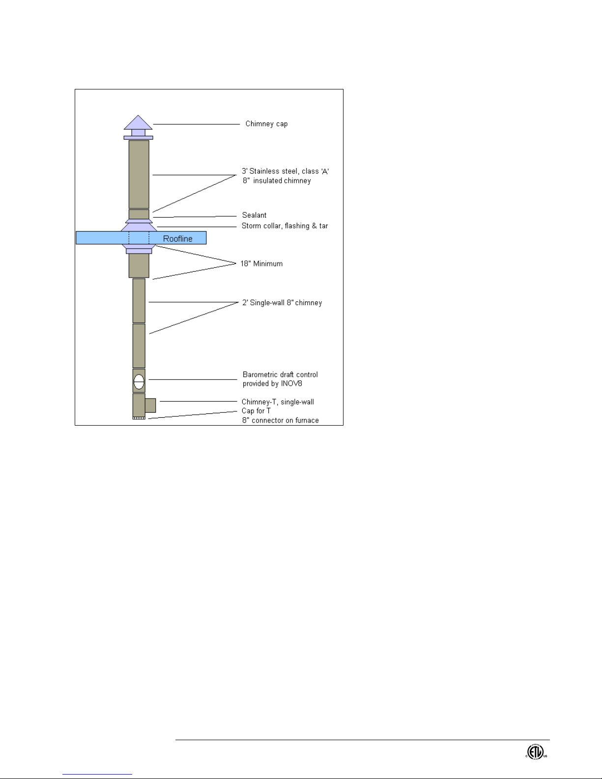
Most installation standards recommend that an insulated stainless steel chimney be used
from a point 18 inches below the ceiling to the top at the rain cap. The purpose of the
insulated chimney is to protect combustible building materials from high temperature, but
it also supports the chimney draft and prevents harmful condensation within the chimney.
For each gallon of oil burned, there is a gallon of water vapor generated as a product of
the combustion process. This water vapor can condense inside the chimney in extremely
cold weather. Some waste oils contain various ingredients that will form acids when
combined with the condensation. These acids will prematurely corrode non-insulated,
non-stainless steel piping and the furnace heat exchanger.
An ideal chimney is attached to the furnace by a ‘T’ fitting and consists of 8” chimney
pipe going straight up through the roof to sufficient height to provide at least 12 feet
between the furnace flue attachment and the top of the chimney. Other items of
importance include:
INOV8 Model F240 – Edited September 2008 9
1. Each furnace must have a dedicated
chimney.
2. New chimney pipe is recommended. Tying
into old stacks often causes problems
because of soot build-up inside the chimney,
too small of interior pipe, the connection
section is often a horizontal piece, concrete
chimneys are cold and difficult to heat up to
create the draft and additional length is
difficult to add.
3. A barometric draft damper and a clean-out
tee must be installed at the bottom of the
vertical chimney.
4. Single-wall flue pipe may be used for
INTERIOR CHIMNEY ONLY! Stack
temperatures in excess of 500oare common.
5. A metal ventilated, approved thimble must
be used when passing through a combus-
tible wall. Once through the wall, DO NOT
use a single-wall component.
6. Sidewall flue installations are prohibited
without written factory authorization.
7. The last stack section must extend at least 3
feet above the highest point at which it
comes in contact with the roof, and at least 2
feet higher than any ridge, parapet wall or
roof structure within 10 feet of the chimney.
8. Install a non-restrictive stack cap (rain cap). In extremely windy locations, a Breidert
type vent cap is recommended. A screen to restrict birds from access to the
chimney is recommended.
9. It may be necessary to install a draft inducer on chimneys that fall short of providing
sufficient draft for whatever reason. See the following section for more information.
INSTALLING THE BAROMETRIC DRAFT CONTROL
The barometric draft control is intended to provide consistent draft, especially in tall
chimneys where there may be excessive draft that could impact the flame. The best
location for the barometric draft control is in the first vertical section within one to three
feet of the furnace. The flapper on the barometric draft control should be installed so it is
facing away from the fan on the furnace. The flapper must be vertical when closed. Use
a spirit level to make sure the barometric draft control is plumb in all directions,
regardless of whether the flue is horizontal, vertical or sloping. Do not attach the
barometric draft control in a horizontal section of flue pipe or in a room separate from the
furnace. See the photo on page 2. Additional installation instructions are included with
each damper.
Typical Chimney Parts

INOV8 Model F240 – Edited September 2008
10
DRAFT MEASUREMENTS &ADJUSTMENTS
Tools Required: Dwyer Pressure Gauge, Draft Rite or Bacharach Draft Gauge
The barometric draft control must be set to maintain proper draft. Draft measurements
must be re-done any time there is a change in the combustion air adjustment located on
the burner housing (secondary air). Follow these instructions for measuring the draft
over the fire:
1. Check the draft while the burner is up to temperature and the cabinet fan is running.
Insert the draft gauge into the ¼” hole in the 2” view port. The measurement must
indicate a draft of 0.02 to 0.04 inches WC (water column) for newly installed or newly
cleaned furnaces. The furnace will not operate properly with a draft less than 0.01.
2. A draft greater than 0.05 will induce excessive heat up the chimney resulting in low
heat output and abnormally high stack temperature. Make necessary adjustments to
the barometric draft damper, according to the factory instruction sheet found in the
box the damper comes in.
INSTALLING AN OPTIONAL DRAFT INDUCER
A draft inducer is a motor driven fan that attaches to the chimney for the purpose of
augmenting the natural draw of that chimney. It may be necessary to install a draft
inducer on chimneys that fall short of providing sufficient draft for some reason or other,
but a draft inducer is not a cure-all: It provides no relief for resonation problems that can
occur in horizontal runs, for instance, and it cannot overcome the effects of an exhaust
system operating within the building. Should you find that your installation requires the
assistance of a draft inducer, install it according to the following guidelines:
Install it just above the barometric draft control in a vertical section, on the opposite side
of the chimney from where the furnace flue pipe enters. Avoid mounting in horizontal
sections for these reasons: a) ash will accumulate on the blades, b) it will be exposed to
excessive heat, and c) it will need to be supported in some manner. A red wire is
provided in the furnace’s electrical junction box which functions to control a relay that
turns the draft inducer on at the proper time. Wire the draft inducer and relay in
accordance with the electrical wiring diagram. Draft inducers are adjustable and may
need to be adjusted to obtain proper draft.
INSTALLING AN OPTIONAL SEALED COMBUSTION SYSTEM
Refer to the burner diagram on page 20 for identification and location of parts.
1. Remove the oil supply line (item #4 on drawing) from the burner pump.
2. Remove the copper ‘U’ shaped tube just above the pump.
3. Disconnect the pump outlet hose from port ‘C’ under the module. Remove the
other end of the hose from the oil pump.
4. Remove the two bolts that secure the oil pump to the burner casing.
5. Remove the oil pump. (The plastic pump shaft drive coupling is made of three
parts: some, all or none of which might remain on the pump shaft during removal.
Put it back together if necessary and slide it all onto the motor shaft.)
6. Remove the two screws that secure the disk shaped secondary combustion air
bands to the burner casing. The screws are just above and below the pump.
7. Remove the disk shaped air band. (It will not be re-installed.)
8. Loosen the cinching screw that binds the disk shaped secondary combustion air
band to the burner casing and remove the bands. (It will not be re-installed.)
9. Install the provided 450 ‘street’ elbow into the hole in the pump from where the
hose was earlier removed. Use thread sealant and turn it to a position such that
the outlet of the elbow will be horizontal when the pump is remounted.

INOV8 Model F240 – Edited September 2008 11
10. Install the provided sheet metal air boot onto the extended casing of the burner.
The provided sponge rubber gasket will seal the boot to the burner casing. The
two slots in the gasket will line up with the two oil pump bolt holes. (Rotate the
air boot until the left side is essentially vertical.)
11. Using bolts saved in step 4 above, re-install oil pump with coupling connecting
both shafts. Be aware that the flat on the pump shaft must align with the flat side
in the coupling. Don’t tighten the bolts yet
12. Re-attach the copper ‘U’ bend removed earlier.
13. Wiggle the boot to make sure it’s properly seated. Then tighten the pump bolts.
14. Attach the pump hose to the 45o‘street’ elbow. Use thread sealant.
15. Re-attach the other end of the hose to port ‘C’ under the module block.
16. Re-install the oil delivery line to the pump inlet with 1/8-27 NPT 45ostreet elbow.
17. Cut a 4” round hole through the wall near the chimney. The termination of the
vent must be on the same plane as the termination of the chimney.
18. Install the provided air intake mechanism and secure it to the wall.
19. The termination of the vent pipe must be at the same plane as the chimney pipe.
20. Connect the f” port on the intake mechanism to the 4” port on the sealed
combustion boot with solid vent hose (Not provided)
21. Secure the hose at both ends with hose clamps. (Not provided)
22. Set the combustion air adjustment knob in the boot to around 60.
23. Assure that the barometric draft control flapper is sealed shut and can no longer
function.
24. Start the furnace and allow time for the chimney to get hot.
25. Make further adjustment to the combustion air as necessary to produce a good
flame. You want as little combustion air as possible to produce a clean flame.
Check the draft to be sure the setting is proper.
NOTE: It is important that the air brought into the burner through the sealed combustion
adapter boot is allowed to warm up. Cold outside air will cool the preheated oil and
cause combustion problems. Longer lengths of vent pipe and/or running it along side the
furnace are two options for pre-warming. Call the factory for other suggestions.

INOV8 Model F240 – Edited September 2008
12
Figure 2 - Typical Installation Diagram (without bench tank)
NOTE: The above diagram is intended for illustration purposes only.
CEILING MOUNT INSTALLATION CONSIDERATIONS
Be aware that the F240 furnace weighs 500 pounds (186 kg) and the F240 SC weighs
550 pounds (205 kg) when planning its installation. Before suspending the unit, check
the supporting structure to ensure it has sufficient load-carrying capacity. The furnace
comes with 5/8" bolts, lock washers and shackles for suspension purposes. Securely
transfer the furnace weight to the roof/ceiling trusses. Use a proper ceiling mounting
system, such as a 2" x 2" x 1/4" angle iron. Lock all mounting components in place using
lock washers and double nuts. It is important that the furnace be hung level side-to-side
and front-to-back and level with the floor. Never hang the furnace with ropes or chains.
ELECTRICAL SUPPLY INSTALLATION
Installation must be done only by a licensed electrician in accordance with the NFPA 70-
2005, National Electric Code® International Electrical Code® Series. See electrical
diagrams in the Addendum. If the furnace has a propeller fan blower, the furnace
requires a 20 amp, 120 volt service. It will have a maximum draw of 17 amps. If the
furnace has a squirrel cage type blower, the furnace requires a 20 amp, 208/240 volt
service including a neutral line. It will have a maximum draw of 17 amps.

INOV8 Model F240 – Edited September 2008 13
FAN/LIMIT CONTROL
The fan/limit controls the on/off function of the motor
that drives the fan or blower unit. It also shuts down
the burner in the event of excessive heat in the
furnace. This safety control is located in the upper
corner (on the louver side of the furnace). Make
certain that the switch has the proper settings: Fan ON
= 140oF, Fan OFF = 80oF, Limit = 170oF. It should
be on the “AUTO” setting.
TANK &PIPING CONSIDERATIONS
OIL STORAGE CONSIDERATIONS
The proper storage and handling of oil is monitored by the federal EPA and most state
environmental agencies, such as the Department of Natural Resources (DNR), your local
Fire Marshall and/or the Regional Environmental Protection Agency. Some states have
adopted more stringent regulations which must be identified and adhered to. Your
installer is responsible for knowing these regulations and of any pertinent application
and/or approval requirements for your oil storage system.
Federal and some state and local regulations restrict the burning of gasoline, paint
thinners and other volatile (low-flash point) solvents, PCBs, benzenes (carburetor
solvent), and fluorinated hydrocarbons (refrigerants). DO NOT add anti-freeze, oil
additives, or paint as these will not burn and cause operating problems.
The instructions found in this manual are general guidelines; exact local regulations must
prevail. Installation of the oil storage and piping must be done by a licensed or qualified
installer in accordance with the pertinent state and local codes and the nationally
accepted standard, NFPA 31 – Standard for the Installation of Oil-Burning Equipment
2006 Edition.
ADDITIONAL OIL STORAGE CONSIDERATION
Many operational problems can be eliminated if proper care is taken in setting up an oil
storage system. All waste oil contains substantial amounts of water and sludge, both of
which settle to the bottom of a tank over a period of time. A storage system that allows
sufficient settlement time will provide trouble free operation. A two-tank system is
recommended allowing one tank to settle while drawing from the other.
Use a fill pipe when adding oil. This fill pipe should extend to within two inches of the
bottom of the tank to minimize the disturbance of the upper oil that is supplied to the
burner. At least once a year the water and sludge should be drained off the bottom of the
tank. If not drained, the pump will draw the water and sludge into the filters and may
cause a shutdown in operation. The tank should be located in close proximity to the
furnace. Inside, outside or buried tanks must be used in accordance with state and local
installation codes.
PIPING &FITTING RECOMMENDATIONS
Air leaks in the oil line will cause sporadic operation. The pipe or tubing size is important
for the best operation of the pump. The following recommendations will produce airtight
connections and trouble-free operations.
1. If the storage tank is inside the building, use 1/2" i.d. (Up to 30 feet to the furnace).

INOV8 Model F240 – Edited September 2008
14
2. If the tank is more than 30 feet away then 1" i.d. or bigger is required (depending on
the distance).
3. Copper piping or iron piping can be used if care is taken with each joint and the line
has a continuous upward incline of at least 1-inch per 1 foot to vent air to the burner.
Flexible copper tubing may be suitable. When using soft copper tubing or plastic
tubing flare fittings are required. Proper sized copper tubing with proper flare fittings
has the least potential for leaks. DO NOT use numerous short lengths of pipe as
each fitting is a potential source of a leak.
4. At no time should pipe unions or compression fittings be used. Sealant (such
as Locktite #565 or Permatex #2 Non-hardening Gasket Sealer) must be used
on all pipe threads.
TANK FILTER
INOV8 provides an in-line filter assembly to be installed in the oil supply line. This filter
will need to changed every six months or as indicated on the filter restriction indicator; the
frequency depends on the type of oil. This filter is a General Filter, model 11V-R2000K
Gar-Ber Fuel/Water Separator. It has a machined aluminum head. The filter dimensions
are: 9” H x 4-3/4” W. It comes with a 1/8” vacuum bleed port, a 3/8” NPT inlet and outlet,
has 10 micron removal, filtering area of 500 square inches, working pressure of 15 psig
and a flow rate of 90 gph, and is UL listed. Replacement elements require part number
R2000 Epoxy-coated Disposable Spin-On Filter.
VAPOR ELIMINATOR FILTER /PRESSURE RELIEF ASSEMBLY
The vapor eliminator/pressure relief assembly located on the burner (see items #2 and
26 on page 20) serves three functions:
1. It vents any vapors that accumulate in the burner’s oil circulating system back to the
oil supply tank.
2. It filters the oil as it is heated and re-circulated at the burner.
3. It shunts the full volume of the pump back to the tank in the event the vapor
eliminator filter should become totally plugged.
INSTALLATION OF VENT LINE FROM VAPOR ELIMINATOR BACK TO THE TANK
A minimum of ¼” copper line or plastic tubing must be run from the compression fitting on
the pressure relief assembly (see item #13 on page 20) back to the oil supply tank.
There must be no valves or constrictions in this line. See “Burner Ignition Start-up” for
adjustment of the valve controlling flow through this line.
1. Insert one end of the return line into the nut and ferrule (provided) on the pressure
relief valve on the vapor eliminator.
2. Run the line along the oil supply line back to the oil storage tank through an available
opening. Make sure the return line nearly touches the bottom of the tank to prevent
loss of prime in the oil supply line. If no opening is available, use a “T” fitting to share
the opening with the supply or fill opening.
3. While the burner is running there should be a steady rapid drip (not a stream) coming
from the end of the return line. Adjust the valve accordingly. Excessive flow will take
all the hot oil back to the tank, inadequate flow will cause vapor to build in the pump.
VAPOR ELIMINATOR FILTER
The filter element in the vapor eliminator canister can plug up over time due to the normal
collection of debris. When the filter is plugged, an amber light on the burner will come on
while the burner is firing to indicate that the filter should be changed. If the filter is not
changed, the pressure relief assembly will vent the over pressured oil back to the tank
through the ¼” return line.

INOV8 Model F240 – Edited September 2008 15

INOV8 Model F240 – Edited September 2008
16
BENCH TANK INSTALLATION
Tanks are available in a variety of sizes and configurations. Our model
T300 HB, a 300 gallon tank with steel supports, holds the INOV8 furnace
eight feet above the floor. Installations using this bench tank are easier
than those without a bench tank because of the ease in mounting the
furnace versus hanging and the short distance for running the oil supply
line. The bench tank comes fully supplied with all necessary fittings for a
complete installation. Many states and cities have additional regulations
regarding the storage of waste or other fuels that may require stricter
measures. It is very important to check with your local fire inspector, or the
proper authority, or a qualified tank installer regarding the requirements in
your area. Refer to these steps for a basic installation.
Figure 3 - Bench Tank Setup
Table of contents
Popular Heater manuals by other brands

Russell Hobbs
Russell Hobbs RHMFHO1 Installation manual and operating instructions

Toyotomi
Toyotomi Toyoset LC-3010 operating manual

Stelpro
Stelpro SCR series user guide

Webasto
Webasto AirTop 2000 S Operating, and servicing instructions

Purmo
Purmo YALI PARADA PLUS Installation and operating manual

Ayce
Ayce DF-150A7-7 manual


Stanley
Stanley ST-23-240-E instruction manual

Soleus Air
Soleus Air HC1-15-12 operating instructions

Bricoman
Bricoman K3CK145NVGBMAN Assembling instructions

Eterna
Eterna SH3WH installation instructions

Dimplex
Dimplex TDTR 175 W Installation and operating instructions

Linea 2000
Linea 2000 DOMO DO7323F manual