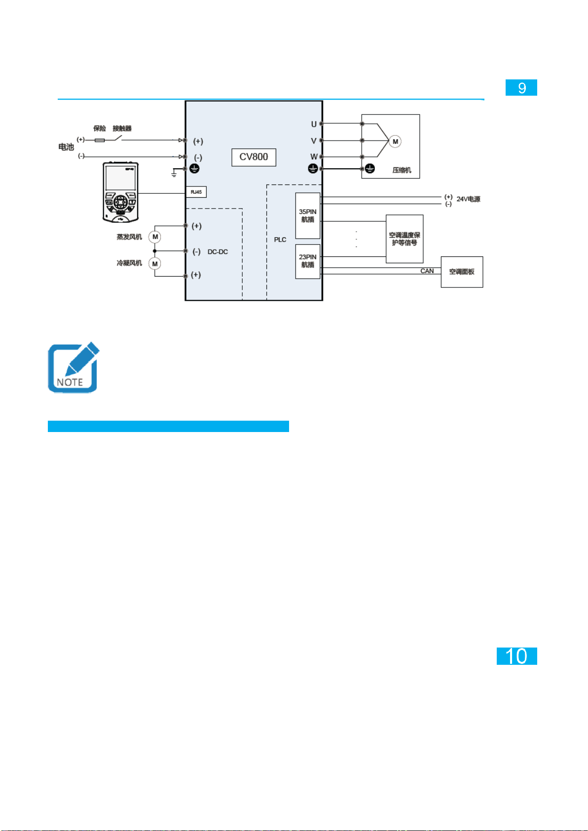
Inovance CV800 Series User manual

User Manual of CV800Series Bus Air Conditioner Driver
A00
File No. 19010605
Safety precautions
Installation precautions
Danger
● When opening the box, please do not install if you find
that the driver has been flooded, any parts are missing or
damaged, or information in the packing list is not in
conformity with the real product name.
● Please install on flame retardant objects such as metal,
and keep away from combustibles, or it may cause fire!
● Please do not use any damaged driver or driver with
missing components. Or there is a danger for injury!
Note
● Do not touch any part of the driver with your hand, or
there is a danger of electrostatic damage!
●The installation base should undergo shock absorption
treatment, and fixed to the frame with four designated
holes in the driver. Strong vibration can cause damage to
the driver!
●The installation position of the driver in the installation
cabin should be conducive to ventilation and heat
dissipation, so as to ensure the heat dissipation effect and
avoid the overheat caused by the sun exposure.
● Use the specified port when the driver is installed, and
stainless steel screws should be used for fixed ports.
●Before installing the cover plate, ensure that the sealing
ring is installed.
Wiring precautions
Danger
● Please confirm that the power supply is in zero energy
state before the connection, otherwise it may cause electric
shock!
● The driver should be grounded properly according to
standard; otherwise it may cause electric shock!
● Do not connect the input power to the output port (U, V, W)
of the driver, pay attention to the marking of the wiring port,
and do not connect the wrong line. Otherwise it will cause
damage to the driver!
● Be sure to close the cover of driver before turning on
power, otherwise it may cause electric shock!
Wiring precautions
Danger
● Unreliable grounding or grounding failure can lead to high
pressure of the driver housing, which may result in personal
safety damage and failure of driver components!
User Manual

● Follow the recommended value of cable in this manual,
and select copper conductor of corresponding size!
●The specification and installation of the main circuit wiring
shall comply with local regulations and relevant IEC
standards.
Operation precautions
Danger
● Do not touch any input or output port of the driver and
peripheral circuits, otherwise it may cause electric shock!
●Do not touch the housing of driver to test the temperature,
otherwise it may cause burns!
● After the driver is powered on, do not force to cut off
external high voltage and low voltage power supply. Follow
the normal sequence to power off the whole vehicle and the
driver!
Danger
● Please do not use contactor to control the start-up and
shut-down of driver, otherwise it may cause damage to the
equipment!
●Please do not change the manufacturer's parameters at
will, otherwise it may cause damage to the equipment!
1. Product information
The CV800 driver consists of three independent parts, PLC, DC-DC and inverter, and CAN communication network is applied for internal
communication.
☞Explanation of Product Model
☞Technical specifications
Item
Specification
Inverter
Basic
function
Maximum output
frequency
Vector control: 0~500Hz; V/F control: 0~500Hz
Carrier
frequency
0.8kHz~12kHz (adjust carrier frequency
automatically according to load characteristics)
Input frequency
resolution
Digital setting: 0.01Hz; simulation setting:
maximum frequency×0.025%
Control mode
SVC open-loop vector control (synchronous
motor); V/F control (asynchronous motor)
Acceleration and
deceleration
curve
Linear or S curve acceleration and deceleration
mode.
Four kinds of acceleration and deceleration time,
with range of 0.0~6500.0s
Automatic
voltage
adjustment
(AVR)
When the grid voltage changes, the output voltage
can be maintained constant automatically
Overvoltage and
overcurrent stall
control
The current and voltage are automatically restricted
during the operation, preventing frequent tripping
due to overcurrent or overvoltage
Fast current
limiting function
Minimize overcurrent failure and ensure normal
operation of inverter
Torque limitation
and control
With "excavator" features, it automatically restrict
torque during operation, preventing frequent
tripping due to overcurrent; the closed-loop vector
model may be applied for torque control
Powerful
background
software
Support inverter parameter operation and virtual
oscilloscope functions
The virtual oscilloscope can be used for graphical
monitoring of the internal state of inverter
Operation
Frequency
source
Operation panel setting, control terminal setting,
and serial communication port setting can be
switched in many ways
Frequency
source
Five frequency sources: digital setting, analog
voltage setting, analog current setting, pulse setting
and serial port setting that can be switched in many
ways
P: three-in-one, with PLC
Identification
Voltage class
D
DC
250V-880V
Identification
Inverter output current (A)
DCDC output
current (A)
025
25
74
032
32
110
CV800: all-in-one type

Item
Specification
Display
and
keyboard
operation
LCD display
Optional part, Chinese/English prompt content
Parameter
copying
Quick replication of the parameters with LCD
operation panel
Program
download
Underlying program can be downloaded with
LCD keyboard
Protection
Protection
function
Motor short circuit detection, input-output
open-phase protection, overcurrent protection,
overcurrent protection, overvoltage protection,
undervoltage protection, overheat protection,
overload protection, etc.
Communi
cation
CAN
Support CAN communication and SAE1939
protocol
Loading
capacity
Full-load voltage
range
Corresponding 220V motor: 311V~880V
Corresponding 380V motor: 540V-880V
Output
derating
Range of voltage
drop
Corresponding 220V motor: 250V~311V
Corresponding 380V motor: 250V-540V
DC-DC
Basic
function
Output voltage
adjustable
Output voltage can be adjustable within the
range 14V~27.5V
Two lines of
output
Two channel output, with common ground
Fast current
limiting function
Brush fan startup can limit the fast
current-limiting startup
Display
and
keyboard
operation
LCD display
Optional part, Chinese prompt content
Parameter
program
modification,
copying and
download
Fast replication of parameters and program
downloads
Protection
Protection
function
Overcurrent protection, overvoltage
protection, undervoltage protection, overheat
protection, overload protection, etc.
Communi
cation
CAN
Support CAN communication and SAE1939
protocol
Loading
capacity
Full-load voltage
range
380V~800V
Output
derating
Range of voltage
drop
250V~380V, 800V~880V
PLC(only three-in-one)
Input and
output
Input terminal
9 channel digit input, 6 channel temperature
input, 2 channel analog input
Output terminal
5 channel digit input, 3 channel relay output, 2
channel analog output
Electronic
expansion valve
Support 4 channel /6 channel 12V/6W
electronic expansion valve (optional)
Communi
cation
Communication
CAN, 485, USB, one channel respectively
Display
and
keyboard
operation
LCD display
Optional part, Chinese prompt content
Monitoring and
download
onitorign of input output Terminal status and
downloading of underlying and application
programs
☞Product parts
Keyboard window cover
LED display window
35pin aviation plug
23pin aviation plug
Main power wiring
cabin cover
Waterproof breather valve
DC-DC output
wiring plug
Cooling fan Grounding terminal
Inverter output wiring plug
Inverter input wiring plug
Fig. 1 CV800 product parts

Part name
Function description
LED display window
Display part of inverter operation failure
information etc.
Keyboard window cover
Open the keypad cover to see RJ45, USB,
communication matching dial switch, 24V control
loop insurance, RUN/STOP switch and PLC
JLINK copying port below
Part name
Function description
35PIN aviation plug
PLC card for external port
23PIN aviation plug
Main power wiring cabin
cover
Open the cover to connect the driver high voltage
input line, inverter motor output line and DC-DC
24V output line
DC-DC output wiring
plug
DC-DC output (1 negative terminal, 2 positive
terminals)
Waterproof breather
valve
Ensure the internal air pressure and external air
pressure are consistent, and the valve is
breathable and waterproof
Inverter input wiring plug
Positive and negative high voltage input
Inverter output wiring
plug
Motor UVW output
☞Keyboard window
Fig. 2 Opened keyboard cover of the driver
Terminal
marking
Terminal name
Description
J5
RJ45
Keyboard interface of inverter, PLC and
DC-DC; dedicated SOP-20-810 keyboard
should be used
S1
AI1
Analog input current and voltage mode jumper
(default voltage mode), dial ON, current mode
AI2
485A+
120Ωmatched resistance, ON enabled
485A-
485B+
120Ωmatched resistance, ON enabled
485B-
CANH
120Ωmatched resistance, ON enabled
CANHL
F1
24V insurance
Total 24V control system insurance, rated
current 5A. mini plug-in car insurance
USB1
USB port
PLC card download program, for background
monitoring
U32
RUN/STOP
switch
Switch of PLC card running
J9/J10
Inverter
controls 5V
power supply
jumper
☞Definition of PLC aviation plug port
◆Definition of 23PIN aviation plug communication port

No.
Signal
definition
Signal description
Remarks
1
RT1+
Channel 1
temperature
sampling
Correspond to soft
component D8400
2
RT2+
Channel 2
temperature
sampling
Correspond to soft
component D8401
3
RT3+
Channel 3
temperature
sampling
Correspond to soft
component D8402
9
RT4+
Channel 4
temperature
sampling
Correspond to soft
component D8403
10
RT5+
Channel 5
temperature
sampling
Correspond to soft
component D8404
16
RT6+
Channel 6
temperature
sampling
Correspond to soft
component D8405
17
RT-
Temperature
sampling common
ground
18
RT-
Temperature
sampling common
ground
4
AD1
Analog input 1
Correspond to soft
component D8406
11
AD2
Analog input 2
Correspond to soft
component D8407
19
AGND
Analog common
ground
8
CANH
CAN
communication+
Fixed 250K baud rate
15
CANL
CAN communication-
20
485A+
Channel 1 485+
Optional, not provided by
default, non-isolated
21
485A-
Channel 1 485-
7
485B+
Channel 2 485+
14
485B-
Channel 2 485-
22
CGND
Communication
reference ground
23
CGND
Communication
reference ground
12
5V
5V power supply
Optional, not provided by
default
5
5V_GND
5V reference ground
6
V+
Keyboard power
supply+
Optional, not provided by
default
13
V-
Keyboard power
supply-
Note: See detailed information of 23PIN commutation aviation plug PLC control card in Annex B.
◆Definition of 35PIN aviation plug communication port
No.
Signal
definition
Signal description
Remarks
1
24V
PLC card power
supply
2
0V
PLC card power
ground

7
DA1
Analog input 1
Correspond to soft
component D8410
17
DA2
Analog input 2
Correspond to soft
component D8411
18
DA3
Analog input 3
Correspond to soft
component D8412 (optional)
29
DA4
Analog input 4
Correspond to soft
component D8413 (optional)
30
AGND
Analog reference
ground
19
EEV1+
First set of coil of
electronic expansion
valve +
Optional, not provided by
default
20
EEV1-
First set of coil of
electronic expansion
valve-
31
EEV2+
Second set of coil of
electronic expansion
valve +
32
EEV2-
Second set of coil of
electronic expansion
valve -
24
12V
Electronic expansion
valve power supply
25
12V_GND
Electronic expansion
valve power ground
3
X00
Set No. 0 X input
Correspond to soft
component X00
4
X01
Set No.1 X input
Correspond to soft
component X01
5
X02
Set No. 2 X input
Correspond to soft
component X02
14
X03
Set No. 3 X input
Correspond to soft
component X03
15
X04
Set No. 4 X input
Correspond to soft
component X04
26
SS0
X input common
terminal
Common terminals X00 to
X04
16
X05
Set No. 5 X input
Correspond to soft
component X05
28
X06
Set No. 6 X input
Correspond to soft
component X06
13
X07
Set No. 7 X input
Correspond to soft
component X07
6
X10
Set No. 8 X input
Correspond to soft
component X10
27
SS1
X input common
terminal
Common terminals X05 to
X10
11
Y10
Relay output of set
No. 0
Correspond to soft
component Y10
12
CMO
Relay output of set
No. 0
22
Y11
Relay of set No.1
Correspond to soft
component Y11
23
Y12
Relay of set No. 2
Correspond to soft
component Y12
35
COM1
Relay reference
ground of set No. 1
and set No. 2
9
Y01
PWM output of set No.
1
Correspond to soft
component Y01
8
Y02
PWM output of set No.
2
Correspond to soft
component Y02
10
Y13
Y output of set No. 1
Correspond to soft
component Y13
21
Y14
Y output of set No. 2
Correspond to soft
component Y14
34
Y15
Y output of set No. 3
Correspond to soft
component Y15
33
COM2
Y output common
terminal
Common terminals Y01 to
Y15
● Optional port, currently single board is left out of welding and cannot be used.
● Only support NTC, NTC specification: R25=5KΩ±1%, B25/50=3470±1%.

● Description of electronic expansion valve: soft component Y00 is used to output motor PWM signals,
Y03 is used to control the motor rotation direction, Y04 is used to control enabling signal of motor
driver chip, and X11 is used to detect alarm signal of motor driver chip.
● X input is source/SINK compatible, and Y resistor output is source type.
2. Installation and wiring
☞Installation dimensions of the product
The largest size of the whole machine is 351*372*166 (including waterproof plug), the base size is
340*340, and the installation dimension is: 320*320 (M8 screw recommended)
35PIN signal port 23PIN signal port
DC-DC low-voltage output port DC input port UVW output port
☞Recommended cables and lugs
Table 2-1 Recommended cables and lugs at DC-DC side
Type
Name
Positive output wire (2
sets)
Negative output wire
Lug
Wiring terminal
M6 OT terminal
M6 OT terminal
Recommended
terminal part no.
GTNR16-6
GTNR25-6
Recommended
terminal manufacturer
Unimag
Unimag
Cable
Wire diameter
16mm²
25mm²
Current
65A
110A
Voltage
27VDC
27VDC
Ambient temperature
70℃
70℃
Number of cores
Single core wire
Single core wire
Automobile grade
Yes
Yes
Cable temperature
125℃
125℃
Special instructions
Fitted with M20
waterproof plug
Fitted with M20
waterproof plug
Table 2-2 Recommended cables and lugs at inverter side
Type
Name
High voltage input
wire
Motor output wire
PE output
wire
Lug
Wiring terminal
M5 OT terminal
M5 OT terminal
M5 OT
terminal
Recommended
terminal part no.
TVR5.5-5
TVR5.5-5
TVR5.5-5
Recommended
terminal
manufacturer
Unimag
Unimag
Unimag

Type
Name
High voltage input
wire
Motor output wire
PE output
wire
Cable
Wire
diameter
6mm²
6mm²
6mm²
Current
40A
32A
32A
Voltage
750VDC
400VAC
400VAC
Ambient
temperature
70℃
70℃
70℃
Number of
cores
Twin-core solid wire
Three-core solid
wire
Single core
wire
Automobile
grade
Yes
Yes
Yes
Cable
temperature
125℃
125℃
125℃
Special
instructions
Fitted with M20
waterproof plug
Fitted with M20
waterproof plug
yellow and
green wire
Table 2-3 Recommended control terminals of 23PIN/35PIN aviation plug
Type
Model
Amount used in unit
set
Manufacturer
23PIN plug
770680-1
1
TE
35PIN
776164-1
1
Pressing lug
770520-1
58
☞Switching cable for vehicle commissioning
In the commissioning of vehicle air conditioning, in order to view status, modify parameters and copy or
download programs of CV800 equipment in the driving cab, it is recommended to use external
SOP-20-810 keyboard for commissioning.
It is recommended that customers make switching cable for commissioning as shown below:
SOP-20-810 keyboard is fitted with RJ45 cable interface.
SOP-20-810 keyboard
CV800 air conditioning driver
Self-made switching cable for commissioning
RJ45 cable
Control panel Pin 1 Definition of RJ45 plugs:
1. CANH
2. CANL
6. 24V+
8. COM
RJ45 plug
Fig.4 Connection diagram of switching cable
Note: See information on description and use of air conditioning panel in IOTWD Series Bus
Air-conditioning Control Panel User's Manual.
☞System wiring diagram
Please follow the wiring diagram below. It is recommended to use automobile grade cables. DC-DC
output has three output terminals and the negative terminal is shared.

Insurance Contactor
Battery Compressor
24V power supply
35PIN aviation plug
Evaporating fan
Air-conditioning temperature protection signal etc.
Condensate fan 23PIN aviation plug Air conditioner panel
• Brush fan: regulate speed directly with internal voltage regulation instructions.
• Brushless fan: please fix DCDC output voltage, and regulate speed with AI port or PWM port of brushless fan
Fig. 5 CV800 system wiring diagram
● Waterproof plugs at DC-DC side should be tightened in turn, otherwise, the middle one will interfere
with the two beside it.
3. Overall debugging
a) Connect the compressor and fan, and input the high voltage into DC power supply;
b) To use external keyboard for debugging, please connect SOP-20-810 keyboard;
c) Debug the inverter and change its parameters;
d) Debug DC-DC, and change DC-DC parameters;
e) Write PLC program, and debug PLC;
f) Start running the air conditioner;
g) After confirming that everything is OK, confirm whether CAN pull-up resistor is correct, and lock the
keyboard cover and main power wiring cabin cover.
☞Operation and speed regulation of inverter
F0-02 Select command source
0: LCD keyboard/background software command channel;
2: communication command channel (CAN), by default.
F0-03 Select frequency source
0: digital setting (F0-08), not saved after power failure;
1: digital setting (F0-08), saved after power failure;
9: communication setting (CAB), by default; other options of the two sets of function codes are not
available. When using PLC to control the inverter, set F0-02 to be 2, and F0-03 to be 9.
☞DC-DC startup and voltage regulation
F4-00: Select startup mode
1: EN enabled to startup, and EN disenabled to shut down the device;
2: EN enabling and CAN sending startup command to start the device simultaneously, and
correspondingly, EN disenabled or CAN sending shutdown command to shut down the device. Default;
3: SOP-20-810 keyboard and DI enabled startup and stop.
F4-01: Voltage regulation mode
1: Voltage regulation, refers to adjust the output voltage with keyboard (default value 27.5V)
2: control source for voltage regulation is CAN, by default
Voltage regulation range is 14-27.5, where the keys F4-11 on the keyboard are used for regulating
voltage of the first module, and the keys F4-12 are used for regulating voltage of the second module.
☞DC-DC parallel connection
The single output of DC-DC is not greater than 65A, and the total output of two channels is not greater
than 110A, where parallel connection mode is available, i.e. positive terminals of two output channels
are short-connected to form one channel output power. Please contact us at this time to apply for short

connected copper bars for parallel connection. It is strictly prohibited to connect two positive terminals
with cable on the far end.
When DC-DC is combined for one channel output, startup command and voltage regulation command
of the first channel will be used as CAN startup command and output voltage regulation command.
F8-14: model options (taking effect after power-on again after completing settings)
1: stand-alone mode, two channel 1.5kW output (default working mode). Please confirm that the
output hardwares of the first channel and the second channel have been separated before setting.
2: parallel connection mode, single channel 3kWoutput. Please confirm that the output hardwares of
the first channel and the second channel have been separated before setting.
Evaporating fan Short connected copper bars
Condensate fan
Condensate fan Evaporating fan
F8-14=1: stand-alone mode F8-14=2: parallel connection mode
Fig. 7 DC-DC stand-alone mode and parallel connection mode
4. Description of external keyboard
To use external keyboard SOP-20-810 for debugging, CV800dedicated HEX configurationfile must be
configured. SOP-20-810 should have built-in matched resistor and pull-up resistor.
CAN communication is used for keyboard communication, and it is within the same network of the CAN
of air conditioning control panel. When 23PIN aviation plug is connected to 24V, the keyboard may
search CV800-DCDC equipment, and connected to 24V and 540VDC, CV800-INV equipment may be
searched. When disconnect 540VDC, CV800-INV will display communication drop. To have
CV800-INV (keyboard scans the equipment once after power-on and the first scanning time may be
1-2min) displayed after power-on again, reinsert he keyboard. Communication of SOP-20-810 LCD
keyboard is carried out with dedicated communication protocol and three devices in CV800. For details
of LCD keyboard upgrade and file configuration, see Appendix A.
Buckle
Fastening screw hole
RJ45 port
Display Nameplate
Keys Battery cover
Status indicator light Fastening screw hole
USB connector
Fig. 6 SOP-20-810 keyboard
●Ordinary digital control keyboard is not supported in CV800 products.
● Driver RJ45 and aviation plug shares the same CAN network, which can be connected to the
keyboard by means of aviation plug switching cable.
If the air conditioning panel used is fitted with built-in resistor, when tested in factory, before inserting
SOP-20-810 keyboard for debugging, toggle the CAN matched resistance of PLC to position “OFF”,
otherwise, communications might be unstable. If SOP-20-810 keyboard is not used, when the air
conditioning is delivered, be sure that PLC is in the position “ON”(i.e., 120Ωmatched resistance is
located at both ends of air conditioning CAN communication network).
DC-DC station number: 7; PLC station number: 32; INV station number: 33

Fig. 7 CV800 CAN communication network
5. Programming copying
☞Copy CV800 equipment underlying program with keyboard
Connect the SOP-20-810 keyboard to the computer via the USB extension cord and select the large
capacity mode from the keyboard display menu to see removable disk on the computer. Copy the
underlying driver .bin file required by DC-DC, inverter and PLC to keyboard SD card:
SYS/PROGRAM/path.
Fig. 8 USB connection completed
Fig. 9 Storage path of copying file
When the CV800 driver is connected to the 24V and 540VDC power supply, keyboard may be used for
underlying upgrade of DC-DC, inverter and PLC after the three devices are searched. See Appendix A
for information on operation.
● Rooting is risky, please keep keyboard on line during the whole copying process. If power failure
occurs, the machine may be damaged.
☞Generation and download of PLC application program
In Autoshop engineering interface, click Tool -->Generate CV800 download file, click “OK”in the
pop-up screen, and then in the pop-up box, select the storage path and name of file to generate.
Format of file is .bin (Chinese name not supported). The copying method is same as that of underlying
programs.
PLC (with built-in
matched resistor)
Air conditioning
panel (with
built-in matched
resistor)
SOP-20-810 (with
built-in matched
resistor)
Please select USB connection mode
USB relay mode
USB mass storage mode
Return Select
• USB mass storage mode

Fig. 10 Generation of PLC application program
Appendix A Keyboard program upgrade
☞Steps of keyboard program upgrade
1) Connect SOP-20-810 keyboard to the computer via the USB port.
2) Get ready the.bin file and copy it into the following path of SD card: 0: /SYS/update; as shown
below.
Fig. 11 Storage path of keyboard upgrade file
3) Keyboard login
Menu-->Authority management-->Keyboard login--> input login password: 37421
After keyboard login, enter the keyboard upgrade menu, i.e. Menu--> System operation --> Keyboard
upgrade, as shown in the figure below:
HEV-BUS-PCU_TM Run HEV-BUS-PCU_TM Run
03 Equipment operation 01 Equipment program copying
04 Authority management • 02 Keyboard upgrade
05 System configuration
• 06 System operation
Return 18:00:02 Select Return 18:00:02 Select
Fig. 12 Keyboard upgrade menu
4) Select the file that needs to be upgraded from the list of files;
Generate CV800 download file

Fig. 13 Select the file to be upgraded
5) Press the "right soft key" in the pop-up confirmation box to confirm the upgrade.
Fig. 14 Confirm upgrade of keyboard
6) Wait for the keyboard to restart and complete the copying.
Fig. 15 Waiting interface during upgrade
☞Import keyboard configuration file
1) Connect the keyboard to the computer via the UBS port to see following contents on the computer.
Please select a file
Return
Select
Please select a file
Return
Return
Select
Select
Are you sure to update the LCD
keyboard program?
The LCD keyboard will be restarted to
complete upgrade. Please wait...

Fig. 16 Storage path of keyboard model information file
2) Copy .hex file as mentioned above into the following path of SD card: 0: /iPanelCfg/; Ensure that for
the same type of electronic tag, only one copy of model information file is available in iPanelCfg folder.
Otherwise, the one being imported first shall prevail.
3) on the basis of step 3, disconnect the power supply from SOP-20-810, manually hold down the
Loc/Rem button before power-on and release the button till the prompt information “Backup Files xx”
occurs. After that, wait till model information file is imported into SOP-20-810;
4) After the import, devices will be automatically searched.
Annex B Description of CV800 PLC control card
☞Functional specification
1) Power input specification
Item
Unit
Min.
Typ.
Max.
Remarks
Rated operating
voltage
Vdc
16V
24V
32V
External power supply
of 24V
2) Digital input specification
Table B-1 Basic specification of digital input
Item
Specification
Item
Specification
Input channel
9
ON voltage
>15VDC
Input
connection
mode
Aviation plug,
pluggable
OFF voltage
<5VDC
Input type
Digital input
Port filtering
time
10ms
Input mode
Source/SINK type
Input impedance
4.3K
Input voltage
class
24VDC (maximum
30V)
Input signal form
Voltage and dc
input, support SINK
type input (SINK)
and source type
input (SOURCE)
Input current
(typical)
5.3mA
Isolation method
Light coupling
isolation
Table B-2 Digital input user interface
Network
name
Type
Function
Remarks
X00~07
Input
Group 1 user input 0~7
Source/leaking type
input
X10
Input
Group 2 user input 0
Source/leaking type
input
S/S
Power
supply
Common terminal
S/S
Power
supply
Common terminal
3) Digital output specification
Table B-3 Basic specification of digital output
Item
Specification
Output channel
3
Output connection mode
Aviation plug, pluggable
Output type
Relay output
Rated current of relay
3A@24Vdc
ON response time
Below 20ms (hardware response
time)
OFF response time
Below 20ms (hardware response
time)
Maximum load
Resistive load
Single point 3A/point
Lamp load
Single point 30W
Inductive load
Single point 5A@24Vdc
Capacitive load
Not recommended
Isolation method
Mechanical isolation
4) Transistor output specification

Table B-4 Digital output user interface
Network name
Type
Function
Remarks
Y10
Output
Relay user output 0
Dry contact
Support 24Vdc only
COM0
Output common terminal
Common terminal
Common terminal of first set of relays
Y11
Output
Relay user output 1
Dry contact
Support 24Vdc only
Y12
Output
Relay user output 2
Dry contact
COM2
Output common terminal
Common terminal
Common terminal of second set of relays
Description of special load usage:
◆Contact protection when inductive load is used
When inductive load is used in the product, it will produce very large back electromotive force between
contacts between when it ceases as well as arc discharge, which may cause the contact failure of
contacts or contact sinking, significantly shortening the service life of contacts. It is recommended to
use products with built-in protection loop. If load without internal protection loop is used, use external
shock protection circuit to reduce noise and prolong the life of the product.
Relay DC loop (Y00/Y01/Y02/COM1)
Connect fly-wheel diodes in parallel on load. Diodes need to meet the following requirements:
①Reverse voltage: 5~10 times of load voltage; ②Forward current: greater than load current.
Inductive load
Fly-wheel diode
◆Contact protection for using capactive load
When using capacitive load, if electric shock occurs, surge current 20 to times greater than the
conventional current may flow through the circuit. Note that the surge current cannot exceed the
current value at the maximum load of the resistance load.
In addition, capacitors and other capacitive loads may be present under the load of electronic circuits
such as inverters.
4) Transistor output specification
Table B-5 Basic output specification of transistor
Item
Specification
Output channel
10
Output connection mode
Aviation plug, pluggable
Output type
Transistor, high side output
Output mode
Source type
Output voltage class
5V~24V (-5%~20%)
The maximum leakage
current when OFF
Below 0.5mA
ON response time
Less than 0.5ms (hardware response
time)
OFF response time
Less than 0.5ms (hardware response
time)
Maximum load
Resistive
load
0.5A/point
Inductive
load
12W/DC24V (in total)
Lamp load
2W/DC24V (in total)
Isolation method
Light coupling isolation
Table B-5 User interface of transistor output
Network
name
Type
Function
Remarks
Y01~02
Output
First set of user
output 1~2
Source output, high
level effective
COM2
Output
common
terminal
Common terminal
Transistor output
common public
terminal 2
Y13~15
Output
Second set of
user output 3~5
Source output, high
level effective
COM2
Output
common
terminal
Common terminal
Transistor output
common public
terminal 2
Description of special load usage:
◆Contact protection when inductive load is used
When inductive load is used in the product, it will produce very large back electromotive force between
contacts between when it ceases as well as arc discharge, which may cause the contact failure of
contacts or contact sinking, significantly shortening the service life of contacts. Thus, to prolong the life
of the product, connect fly-wheel diodes in parallel on load if necessary.
Diodes need to meet the following requirements: ①Reverse voltage: 5~10 times of load voltage; ②
Forward current: greater than load current.
Programmable Controller
Output Contact

Inductive load
Fly-wheel diode
5) NTC temperature sampling specification
Table B-7 Basic specification of NTC temperature sampling
Item
Specification
Item
Specification
Input channel
6
Sensitivity
0.1℃
Input connection
mode
Aviation plug,
pluggable
Precision
(room
temperature 25
℃)
Full scale *(±0.5%)
Sensor type
Thermal
resistance:
NTC
Precision
(ambient
temperature
-25~65℃)
Full scale *(±1%)
Detection mode
℃
Temperature
measurement
range
-40℃~105℃
Thermal
resistance wiring
Two wire
system
Isolation
method
Between channels:
non-isolated
Resolution
12 bit
Table B-8 NTC temperature sampling user interface
Network name
Type
Function
PT1+
Input
Positive NTC thermal resistance
input of Channel 1
PT1-
Input
Negative NTC thermal resistance
input of Channel 1
PT2+
Input
Positive NTC thermal resistance
input of Channel 2
PT2-
Input
Negative NTC thermal resistance
input of Channel 2
PT3+
Input
Positive NTC thermal resistance
input of Channel 3
PT3-
Input
Negative NTC thermal resistance
input of Channel 3
PT4+
Input
Positive NTC thermal resistance
input of Channel 4
PT4-
Input
Negative NTC thermal resistance
input of Channel 4
PT5+
Input
Positive NTC thermal resistance
input of Channel 5
PT5-
Input
Negative NTC thermal resistance
input of Channel 5
PT6+
Input
Positive NTC thermal resistance
input of Channel 6
PT6-
Input
Negative NTC thermal resistance
input of Channel 6
6) Analog input specification
Table B-9 Basic specification of analog input
Item
Specification
Item
Specification
Input channel
2
Current
input range
0mA~20mA
Input
connection
mode
Aviation plug,
pluggable
Resolution
12 bit
Voltage input
impedance
>400kΩ
Precision
(room
temperature
25℃)
Voltage ±1%, current
±1% (full range)
Current
sampling
impedance
250Ω
Precision
(ambient
temperature
-25~65℃)
Voltage ±3%, current
±3% (full range)
Voltage input
range
0V~10V
Isolation
method
Non-isolated
Table B-10 Analog input user interface
Network name
Type
Function
AVI1
Input
Positive analog voltage
input
Programmable Controller
Output Contact

AVI2
Input
Positive analog current
input
AGND
Input
Analog voltage/current input
ground
7) Analog output specification
Table B-11 Basic specification of analog output
Item
Specification
Item
Specification
Output
channel
4
Precision (room
temperature 25℃)
Voltage ±1% (full
scale)
Input
connection
mode
Aviation plug,
pluggable
Precision
(ambient
temperature-25~6
5℃)
Voltage ±5% (full
scale)
Voltage
output load
500Ω~1MΩ
Isolation method
Non-isolated
Voltage
output range
0V~10V
Output
short-circuit
protection
Yes
Table B-12 Analog output user interface
Network
name
Type
Function
DA1
Output
Positive analog voltage output of
Channel 1
DA2
Output
Positive analog voltage output of
Channel 2
DA3
Output
Positive analog voltage output of
Channel 3
DA4
Output
Positive analog voltage output of
Channel 4
AGND
Output
Analog voltage output ground
☞Instructions for use
1) Programming tool- AutoShop
Please use AutoShop V2.50 and above version software (please visit
the website www.inovance.cn for the latest version) as background
programming software of the product. The software will be used for
application programming and download monitoring. For engineering
PLC type, select H1U-XP. The maximum program capacity of the
system is 16K program.
2) Soft component
Component
Name
Number
Storage characteristics
X
Input relay
9 points
Not saved
X000-X010(octal number
system)
Y
Output relay
8 points
Not saved
Y01, Y02, Y10, Y11,
Y12, Y13, Y14, Y15
Y
PWM output
2 points
Not saved
Y01, Y02
M
Auxiliary
relay
3328
points
Not saved
M0-M1999
Saved
M2000-M2511
Not saved
M2512-M3071
Saved for
special use
M8000-M8511
S
Status relay
1000
points
Not saved
S0-S899
S900-S999[for sending
signal alarm]
Special use
S0-S9[for initialization]
S10-S19[for regression
through the origin]
T
Timer
256
points
Not saved
T0-T199[100ms]
T200-T245[10ms]
T246-T249[1ms
cumulative]
T250-T255[100ms
cumulative]
C
Counter
235
points
Not saved
C0-C199[16 bit counting]
Saved
C200- C234 [32 bit
reversible counting]
Component
Name
Number
Storage characteristics
D
Data register
8512
points
Not saved
D0-D1999
Saved
D2000-D3023
Not saved
D3024-D7999
Saved for
special use
D8000-D8511
V
Index
register
32
points
Special use
V0-V31

Z
Index
register
32
points
Special use
Z0-Z31
Constant
K
16 bit
[-32768~32767]
32 bit [-2147483648~2147483647]
Constant
H
16 bit [0~0XFFFF]
32 bit [0~0XFFFFFFFF]
3) Communication function
The controller supports RS485 (COM0) and CAN communication function, and may meet different
communication needs of customers. Matched resistors are provided for CAN communication and
COM0 RS485 communication and can be enabled or disenabled with the dial switch. 8pin dial switch
as shown below is applied. And the dial switch is OFF by default.
AI1 AI2 RS485A matched RS485B matched CAN matched
resistor resistor resistor
◆RS485 communication function
For the controller and inverter, communication COM1 with the controller is achieved through internal
connector.
◆COM1 communication interface
COM1 is same as that of general version PLC. For details on usage, please refer to COM1 of general
version PLC.
◆CAN communication function
Controller CAN communication supports free protocol conforming to CAN2.0 protocol specification.
CAN communication baud rate: fixed to be 250 kbps.
The schematic diagram of CAN networking is as follows:
Support CANTX and CANRX free protocol command, J1939 communication protocol is implemented
by user program, and CANLink protocol is not supported. The special components for CAN
communication include:
M
component
Description of M
component
D
component
Description of D
component
M8285
Reserved
D8285
Current baud rate,
unit: kbps
M8286
Reserved
D8286
Reserved
M
component
Description of M
component
D
component
Description of D
component
CAN bus
120Ωterminal
resistor
configurable
120Ωterminal
resistor
configurable
Set terminal
resistor with dial
switch of the main
module
Set terminal
resistor with dial
switch of the
subordinate
station
Set terminal
resistor with dial
switch of the
subordinate
station
Main station
Subordinate station 1
Subordinate station N

M8292
0: CANRX command
received or idle
1: CANRX command
receiving state
D8292
The length of data
received by CANRX
M8293
CANTX command
failed to be sent
D8293
Reserved
M8294
CANRX command
received
D8294
Reserved
M8298
0: CANTX command
sent or idle
1: CANTX command
send state
D8298
Reserved
M8299
CANRX command
receipt timeout
D8299
CANTX timeout
setting (ms)
CANTX/CANRX command is designed to facilitate communication between user and equipment of
third party with CAN communication function. With the command, users may write any CAN
communication user protocol.
Format of command is as follows,
CAN data sending
command
CANTX [ S1 S2 D n ]
CAN data sending
command
CANRX [ S1 S2 D n ]
S1, S2: CAN address is made up of the two parameters;
The bit15 and bit14 of S1 are retained, bit13 of S1 is for setting CAN address size, where "0"
represents standard CAN address (11 bits), "1" represents extended CAN address (29 bits). An 11-bit
address should be represented by bit0~bit10 of S2, S1 is 0 and S2 is not greater than H7FF. A 29-bit
address should be made up by S2 (low 16 bit address) and bit0~bit12 of S1 (high 13 bit address),
where bit13 of S1 is 1.
D: D refers to send buffer in CANTXcommand, receive buffer in CANRX command; the maximum four
D components that start with the D component are used as the send or receive buffer.
n: n refers to number of data sent in CANTX command, number of data received in CANRX command;
the maximum number of bytes is 8.
4) Analog input/output function
6-channel PT100 input, 1-channel analog voltage input, 1-channel analog current input, 4-channel
analog voltage output are supported. Special components involved include:
M
component
Description of M
component
D component
Description of D component
Input filtration coefficient
M8390
Reserved
D8390
Temperature sensor 1
input
Input filter coefficient
Setting range: 1~64
Default value: 8
Clear PLC program
or data component to
reset to the default
values
M8391
Reserved
D8391
Temperature sensor 2
input
M8392
Reserved
D8392
Temperature sensor 3
input
M8393
Reserved
D8393
Temperature sensor 4
input
M8394
Reserved
D8394
Temperature sensor 5
input
M8395
Reserved
D8395
Temperature sensor 6
input
M8396
Reserved
D8396
Voltage/current input
M8397
Reserved
D8397
Voltage/current input
M
component
Description of M
component
D component
Description of D component
Temperature sensor 100 Thermal resistance temperature
M8400
Temperature
sensor 1 input
Disconnection
symbol of
temperature
sensor input
D8400
Temperature sensor 1
input
Temperature sensor
input temperature
-400~1050:
-40.0~105.0℃
disconnection value:
-32768
M8401
Temperature
sensor 2 input
D8401
Temperature sensor 2
input
M8402
Temperature
sensor 3 input
D8402
Temperature sensor 3
input
M8403
Temperature
sensor 4 input
D8403
Temperature sensor 4
input
M8404
Temperature
sensor 5 input
D8404
Temperature sensor 5
input
M8405
Temperature
sensor 6 input
D8405
Temperature sensor 6
input
Analog input
M8406
Reserved
D8406
Voltage/current input 1
Voltage: 0~20000:
0~10V
Current: 0~10000:
0~20mA
M8407
Reserved
D8407
Voltage/current input 2
Analog output
M8410
Reserved
D8410
Voltage 1
output
0~10000: 0~10V
M8411
Reserved
D8411
Voltage 2
output
M8412
Reserved
D8412
Voltage 3
output
M8413
Reserved
D8413
Voltage 4
output
Annex C Troubleshooting and parameters of inverters

☞Troubleshooting
Fault name
Panel display
Troubleshooting
Countermeasure
Current
detection
fault
Inverter current
sampling abnormal
Check whether the main circuit is
powered on; whether Hall sensor,
or current sampling device is
damaged, and contact the
manufacturer.
Acceleration
overcurrent
Inverter output circuit is
grounded or short
circuited
Eliminate peripheral faults, detect
whether the motor or delay
contactor is short circuited.
The control mode is
FVC or SVC, without
performing parameter
tuning
Set and tune motor parameters
according to the motor nameplate.
Rapid acceleration, too
short acceleration time
setting
Increase the acceleration time.
Improper overcurrent
stall suppression
setting
Confirm that overcurrent stall
suppression function (F3-19) has
been enabled;
Set value of overcurrent stall action
current (F3-18) is too large, and is
recommended to be adjusted
within the range from 120% to
160%; set value of overcurrent stall
suppression gain (F3-20) is too
small and is recommended to be
adjusted within the range from 20
to 40.
Improper manual
torque magnification or
V/F curve
Adjust the manual torque
magnification or V/F curve.
Start the motor that is
rotating
Select speed tracking startup or
start the motor until it stops.
Fault name
Panel display
Troubleshooting
Countermeasure
Acceleration
overcurrent
Subject to external
interference
Check the history failure record. If
the current value when a failure
occurs is far from the overcurrent
value, find the interference source.
If no other interference source is
found, the driver board or Hall
device might be faulted.
Deceleration
overcurrent
Inverter output circuit is
grounded or short
circuited
Eliminate peripheral faults, detect
whether the motor is short circuited
or the circuit is open.
The control mode is
FVC or SVC, without
performing parameter
tuning
Set and tune motor parameters
according to the motor nameplate.
Rapid deceleration, too
short deceleration time
setting
Increase the deceleration time.
Improper overcurrent
stall suppression
setting
Confirm that overcurrent stall
suppression function (F3-19) has
been enabled;
Set value of overcurrent stall action
current (F3-18) is too large, and is
recommended to be adjusted
within the range from 120% to
160%; set value of overcurrent stall
suppression gain (F3-20) is too
small and is recommended to be
adjusted within the range from 20
to 40.
No brake unit and brake
resistor are installed
Install brake unit and brake
resistor.
Subject to external
interference
Check the history failure record. If
the current value when a failure
occurs is far from the overcurrent
value, find the interference source.
If no other interference source is
found, the driver board or Hall
device might be faulted.
Constant
speed
overcurrent
Inverter output circuit is
grounded or short
circuited
Eliminate peripheral faults, detect
whether the motor is short circuited
or the circuit is open.
The control mode is
FVC or SVC, without
performing parameter
tuning
Set and tune motor parameters
according to the motor nameplate.
Improper overcurrent
stall suppression
setting
Confirm that overcurrent stall
suppression function (F3-19) has
been enabled;
Set value of overcurrent stall action
current (F3-18) is too large, and is
recommended to be adjusted
within the range from 120% to
160%; set value of overcurrent stall
suppression gain (F3-20) is too
small and is recommended to be
adjusted within the range from 20
to 40.
In stable operation state, if the
running current exceeds the rated
Table of contents