manuals.online logo
Brands
  1. Home
  2. •
  3. Brands
  4. •
  5. Fujitsu
  6. •
  7. Air Conditioner Accessories
  8. •
  9. Fujitsu 9319446004 User manual

Fujitsu 9319446004 User manual

En-1
AIR CONDITIONER
OPTIONAL PARTS
External connect kit
PART NO. 9319446004
INSTALLATION MANUAL
For authorized service personnel only.
1. SAFETY PRECAUTIONS
WARNING This mark indicates procedures which, if improperly performed,
might lead to the death or serious injury of the user.
When installing each wire, please thoroughly read this manual.
Before installation be sure that all sources of power have been shut off.
There is a danger of electric shock.
For input/output, use the voltage as described in the signal specications.
Using voltage of other specications may result in malfunction and erroneous operation
of the airconditioner.
CAUTION
This mark indicates procedures which, if improperly performed,
might possibly result in personal harm to the user, or damage
to property.
Do not pull on the connectors with too much force.
2. ABOUT THE UNIT
2. 1. Main Unit & Accessories
• The following installation parts are supplied. Use them as required.
Name and Shape Q’ty Application
Installation
manual
1
This manual
Wire (External input):
Orange / Yellow
1
For connect to External device for
input.
Wire (External output):
Blue / Purple
1
For connect to External device for
operation status output.
Wire (External output):
Red / White
1
For connect to External device for
error status output.
Binder clamp
1
For xing the binder.
Binder
1
For xing the wires.
Screw
1
For xing the binder clamp.
3. SETTING
3. 1. External Input
3. 1. 1. Control Input (Operation/Stop or Forced stop)
• The air conditioner can be remotely operated by means of the following on-site work.
"Operation/Stop" mode or "Forced stop" mode can be selected with function setting of
indoor unit.
Circuit diagram example
Indoor unit
PC board of
communication kit
Connector
Orange
Yellow
Connected unit
Ex.) Switch
10m *
Signal
Field supply
* Make the distance from the PC board to the connected unit within 10m.
Contact capacity : 24VDC or more, 10mA or more.
● When function setting is "Operation/Stop" mode
Input signal
Indoor unit
OFF
Stop
ON
Operation
● When function setting is "Forced stop" mode
Indoor unit
Input signal
Command
Remote controller
Remote control operation invalidity
Normal
Stop
OFF
Forced stop
Operation
ON
ON ON ON
NOTE
• Operation mode, temperature, and airow cannot be set by external input. Use the
remote controller to set.
• If the air conditioner is activated by external input, it will operate in the settings before
stop. To change the settings, use the remote controller.
9319446004_UTY-XWZXZ5_IM.indd 1 2011/03/18 19:21:03
En-2
3. 2. External Output
3. 2. 1. Operation Status Output
• An air conditioner operation status signal can be output.
Circuit diagram example
Indoor unit
PC board of
communication kit
Connector
Blue
Purple
Connected unit
Ex.) Relay unit
~24V DC Ex.) Display
Relay
Power
supply
10m *
Signal
Field supply
* Make the distance from the PC board to the connected unit within 10m.
Relay spec. : Max.24V DC, 10mA to less than 500mA.
Indoor unit
Output signal
Stop
OFF
Operation
ON
NOTE
• Only operation and stop signals will be output.
Use the remote controller to check the operation mode, temperature, and airow.
3. 2. 2. Error Status Output
• An air conditioner condition normal/error status signal can be output.
Circuit diagram example
Indoor unit
PC board of
communication kit
Connector
Red
White
Connected unit
Ex.) Relay unit
~24V DC Ex.) Display
Relay
Power
supply
10m *
Signal
Field supply
* Make the distance from the PC board to the connected unit within 10m.
Relay spec. : Max.24V DC, 10mA to less than 500mA
Error status
Output signal
Normal
OFF
Error
ON
NOTE
• Only error signals will be output.
Check the error information on the display area of the main unit.
4. CONNECTING TO INDOOR UNIT
• Connect the connector to the board of the air-conditioner.
To connect to the air-conditioner, refer to the installation manual of the air-conditioner.
• Connect the tip of the wire to the external equipment.
If necessary, extend it with locally procured wire.
• Ensure that the connecting part is insulated for protection.
9319446004_UTY-XWZXZ5_IM.indd 2 2011/03/18 19:21:03
Other Fujitsu Air Conditioner Accessories manuals

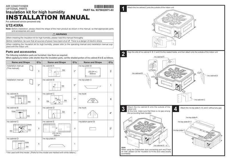
Fujitsu UTZ-KXRA User manual

Fujitsu

Fujitsu UTZ-KXRA User manual

Fujitsu Airstage UTY-DTGYZ1 User manual

Fujitsu

Fujitsu Airstage UTY-DTGYZ1 User manual

Fujitsu UTY-XWZXZ3 User manual

Fujitsu

Fujitsu UTY-XWZXZ3 User manual

Fujitsu UTZ-KXGC User manual

Fujitsu

Fujitsu UTZ-KXGC User manual

Popular Air Conditioner Accessories manuals by other brands

Daikin KPW5E112 installation manual

Daikin

Daikin KPW5E112 installation manual

Mitsubishi Electric PAC-DRP10DP-E2 installation manual

Mitsubishi Electric

Mitsubishi Electric PAC-DRP10DP-E2 installation manual

Kampmann Venkon KaControl quick guide

Kampmann

Kampmann Venkon KaControl quick guide

Trane BAYCOVR112 Installer's guide

Trane

Trane BAYCOVR112 Installer's guide

Midea Wi-Fi CMI user manual

Midea

Midea Wi-Fi CMI user manual

Olimpia splendid B0568 instructions

Olimpia splendid

Olimpia splendid B0568 instructions

Tecnosystemi SCUDO user manual

Tecnosystemi

Tecnosystemi SCUDO user manual

GE RAB24 installation instructions

GE

GE RAB24 installation instructions

Inovance CV800 Series user manual

Inovance

Inovance CV800 Series user manual

Daikin RRDQ220V1 Operation manual

Daikin

Daikin RRDQ220V1 Operation manual

manuals.online logo
manuals.online logoBrands
  • About & Mission
  • Contact us
  • Privacy Policy
  • Terms and Conditions

Copyright 2025 Manuals.Online. All Rights Reserved.