5.3.19 357-00016-01 Rev A © Inovonics, 2019 - www.inovonics.com 3
1. Listed UL 1481, regulated, power limited power supply.
2. Relay 3 is kept activated to monitor power. Note that the NO and NC
terminal positions are reversed.
3. Optional remote reset can be activated by a momentary short between
ground and reset terminals.
4. The zone type (point function) shall be set at fire alarm or supervisory,
depending on application.
3 Registering the Transmitter
3.1 Quick Setup
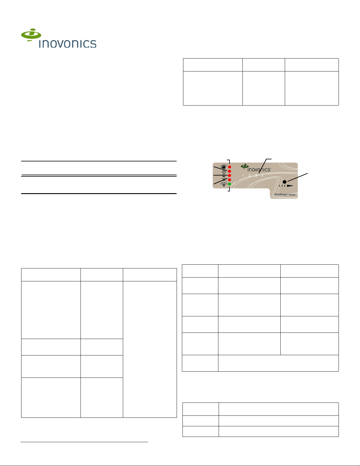
1. Press the advance button one time to select the first initiating device.
2. Press the program button once to select the default programming
options.
3. The first initiating device number will be flashing, indicating it is awaiting
the transmitter’s reset message; press the transmitter’s reset button.
Note: After registering the transmitter, there is no need to exit programming
mode. The receiver is normal operation once the transmitter’s reset button
has been pressed.
Note: The registration is not complete until all LEDs turn off and the
initiating device number lights.
All of the alert LEDs will turn off when the receiver has received the
transmitter’s registration message, and the initiating device number LED
will light for two seconds. This indicates the receiver has received the
transmitter’s registration message. If this does not occur, press reset on the
transmitter again.
3.2 Mount the Receiver
Caution: Mount the receiver in a location removed from metal. Metal
objects (duct work, wire mesh screens, boxes) will reduce RF range.
Note: The EH4104R must be in the same room as the control panel.
1. Use the provided anchors and screws to mount the receiver in a
location accessible for future maintenance, making sure the housing is
flush with the wall and the back tamper switch is actuated.
2. After the transmitter has been registered, perform a walk test, activating
each transmitter assigned to the receiver and ensuring a good signal.
4 Return to Factory Configuration
The EH4104R can be returned to factory defaults using the following .
Caution: The factory config will erase all programmed initiating device,
output, and language information.
To restore the factory configuration defaults to the receiver:
1. Hold down the reset and advance buttons.
2. With the buttons held down, cycle power.
3. Wait for the switch LED to light, then release buttons.
5 Specifications
Compatible transmitter: EH1115EOL.
Compatible control panel: Compatible listed UL 864 control panel with a
minimum of five conventional initiating device circuits (IDC).
Housing: 6.38" x 3.60" x 1.10" (162 mm x 92 mm x 28 mm).
Operating environment: 32°- 140°F (0°- 60°C), 93% relative humidity, non-
condensing.
Power requirement: 11 - 14 VDC; 400 mA; listed UL1481, regulated, power
limited power supply.
Current consumption: Approx. ~400 mA max with all five relays energized.
Output specifications: Form C relay 1A @ 28 VDC, 0.5A @ 30 VAC
resistive load.
Reset input: Contact closure, momentary low.
Receiver type: Frequency hopping spread spectrum.
Operating frequency: 902-928 MHz.
Number of initiating devices/transmitters: One.
Number of alarm outputs: One Form C relay output.
Number of trouble outputs: Four form C relay outputs.
UL listings: UL 864 10th Edition.
6 UL Requirements
• The receiver tamper and transmitter tamper cannot be combined in
one loop.
7 Television and Radio Interference
This equipment has been tested and found to comply with the limits for a
Class B digital device, pursuant to Part 15 of the FCC Rules. These limits
are designed to provide reasonable protection against harmful interference
in a residential installation. This equipment generates, uses and can
radiate radio frequency energy and, if not installed and used in accordance
with the instructions, may cause harmful interference to radio
communications. However, there is no guarantee that interference will not
occur in a particular installation. If this equipment does cause harmful
interference to radio or television reception, which can be determined by
turning the equipment off and on, the user is encouraged to try to correct
the interference by one or more of the following measures:
• Reorient or relocate the receiving antenna.
• Increase the separation between the equipment and receiver.
• Connect the equipment into an outlet on a circuit different from that to
which the receiver is connected.
• Consult the dealer or an experienced radio/TV technician for help.
Optional
remote reset:
External reset
circuit
Reset Aux relay: NO Reset RF
receiver
Ground GND (NEG) Aux relay:
Common
See note 3
below
EH4104R
Function
EH4104R
Terminal
Panel
Terminal Description