Inracks Summit Deluxe Console User manual

Page 1
Summit Console Assembly Guide -REV E
Summit Deluxe Console Assembly
Guide

Page 2
Summit Console Assembly Guide -REV E
Summit Deluxe Console Assembly
Guide
Contents
Please Read Before Assembly ...................................................................................... 2
Legs and Anti-Sag Bars................................................................................................ 3
Corners and Baying...................................................................................................... 7
Modesty panels .......................................................................................................... 11
End panels ................................................................................................................123
Cable Management .................................................................................................... 14
Power Distribution Units............................................................................................ 15
Slatwall ....................................................................................................................156
Cable Grommets........................................................................................................21
Monitor Arms ............................................................................................................212
Data Ports.................................................................................................................. 22
Warranty………………………………………………………………………………………………………………………………………23
Please Read Before Assembly
NOTE: Professional installation is available.
NOTE: Before installing your Summit™Console, be sure and reference the floor plan created
during the order process. Stage your consoles so that they are close to their final position to
insure that everything will fit as intended. Once the consoles are assembled they are not able to
be moved without risk of damage. So locating and leveling before assembly is a crucial step in
getting the most out of your Summit™ Consoles.
WARNING: To avoid damage or injury, Inracks Inc. recommends that you take the time to level
and stabilize the Summit™ consoles in their final location before installing any equipment. Please
take the time to follow all instructions and if you have any questions please call
716-691-8300
BE GREEN: Shipping materials are recyclable. Please save them for later use or, dispose of them
appropriately.

Page 3
Summit Console Assembly Guide -REV E
Unpacking your Summit Console
Unpack your Summit™ console components, use care if using a knife to open packages that you
don't damage any contents. Inspect for any shipping damage. If shipping damage or defects are
suspected contact Inracks Inc. Immediately. Some components can be heavy and may require
help in handling.
Summit™ Console Assembly
Recommended tools:
Electric screw gun with a #2 Phillips tip
Two levels 18 - 24 inch long, one for left to right measurements and one for front to back
measurements
1/4" socket wrench or nut driver
3/4" wrench (for slat wall configurations)
Legs and Anti-Sag Bars
Place the work surface face down on the floor. It's recommended that you use cardboard or other
material to protect the work surface from potential damage while it's resting face down on the
floor. See figure (1) for pilot hole identification.
figure (1)
Pilot Hole Identification

Page 4
Summit Console Assembly Guide -REV E
WARNING: If using a screw gun take care to make sure that the clutch is set so that screws to
not strip out pilot holes when installing. This precaution applies to all millwork components.
Install the legs using a Phillips screwdriver or screw gun with a #2 Phillips tip. Use the #8 x 3/4"
Truss head screws. See figure (2) and figure (3)
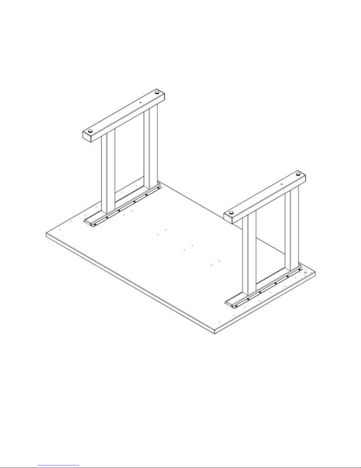
Page 5
Summit Console Assembly Guide -REV E
figure (2)
figure (3)
Completed leg installation

Page 6
Summit Console Assembly Guide -REV E
Install the anti-sag bar using a Phillips screwdriver or screw gun with a #2 Phillips tip. Use the
#8 x 3/4" Truss head screws. See figure (4)
figure (4)
Once the anti-sag bar is in place stand the Summit™ console up on the legs, depending on the
size of the console this might require two people.
After all your Summit™ console are assembled the next step will be installing the corner work
surfaces and baying the consoles together.

Page 7
Summit Console Assembly Guide -REV E
Corners and Baying
WARNING: Before installing corners or baying Summit™ consoles together position the consoles
in their final positions. Once corners are installed or consoles are bayed together they are not
intended to be moved! Trying to move consoles after installing corners or baying together can
cause damage!
NOTE: Forward and reverse corners at or near 90 degrees will include anti-sag bars due to the
span of the corner. Corners less than that do not require anti-sag bars. Assembly image shows a
90 degree forward corner with anti-sag bar.
TIP: Mount the plates using the round holes in the plate first. Using the round holes first will place
the plate in a fixed position. This will allow some adjustment with the oval holes in the plate when
installing the corner work surface or baying the consoles together.
Install the corner support/baying plates to the bottom of the work surface using the #8 x 3/4"
Truss head screws. Figure (5)
figure (5)

Page 8
Summit Console Assembly Guide -REV E
Next, place the corner work surface on the plates. Position the consoles so that seams are minimal
and console work surfaces line up with corner work surfaces. This step is only to ensure that the
consoles are in the correct position before leveling. Before leveling remove the corner work
surface and set it aside.
IMPORTANT: At this time you will want to level the consoles. Place a level on the work surface
from left to right. Using a 1/4" socket wrench or 1/4" nut driver adjust the leveling feet until the
console is level. If protective cap is in place on the leg remove it to gain access to the top of the
leveling foot. Be sure to adjust console for level installation along both the front to back and left
to right planes. Turning the leveling foot from the top, right will raise the console and left will
lower it. Figure (6) . After leveling replace or install protective caps over leveling feet access
holes.
Figure (6)

Page 9
Summit Console Assembly Guide -REV E
Once the consoles are level ensure the corner work surface is aligned. Using the #10 x 7/8" zinc
plated, washer head screws attach the corner work surface to the plates. If anti-sag bar is used
install it at this time using the #8 x 3/4" Truss head screws. Figure (7). For baying see figure (8).
Figure (7)

Page 10
Summit Console Assembly Guide -REV E
figure (8)
After all the consoles and corners are in place and secured you can proceed to install the rest of
your Summit™ console

Page 11
Summit Console Assembly Guide -REV E
Modesty Panels
NOTE: Modesty panels finish the look of your Summit™ console. they also provide an area for
mounting power distribution units and cable management components.
WARNING: If installing the slat wall option do that first! Modesty panels will have to be removed
to install the slat wall option if they are already in place. See page 16 for slat wall option
installation.
Modesty panels are installed on the consoles using the modesty panel retaining brackets. While
both sides of the modesty panels are finished only one side of the modesty panels will have small
pilot holes. This step may be easier with a helper to hold the modesty panel in place while you
are installing the screws.
Place the modesty panel on top of the rear portion of the legs. Fasten the modesty panel retaining
brackets with the #8 x 3/4" Truss head screws to the modesty panel. Only one side of the
modesty panel will have the pilot holes for the mounting brackets. The bracket should wrap
around the vertical part of the leg, with brackets installed at both legs the modesty panel will be
secured in place. Figure (9)
figure (9)

Page 12
Summit Console Assembly Guide -REV E
Corner Modesty Panels
NOTE: Modesty panels finish the look of your Summit™ console. they also provide an area for
mounting power distribution units and cable management components.
WARNING: If installing the slat wall option do that first! Modesty panels will have to be removed
to install the slat wall option if they are already in place. See page 16 for slat wall option
installation.
Corner Modesty Panels are installed at corners to extend the console modesty panels through the
corners. Corner Modesty panels are secured with two corner modesty panel mounting plates and
the #8 x 3/4" Truss head screws. While both sides of the corner modesty panels are finished only
one side of the corner modesty panel will have small pilot holes that align with the corner modesty
panel mounting plate. This step may be easier with a helper to hold the corner modesty panel in
place while you are installing the screws. The existing modesty panels that the corner modesty
panels with be secured to might require pilot holes to be drilled on site. If the corners are part of
a pre defined configuration when shipped, the pilot holes will be drilled at the factory. Use caution
if drilling pilot holes. Ensure their correct location and DO NOT drill through the panel, the holes
only need to be 1/4-1/2 deep. Figure (10)
Note: Console leg was hidden to show corner mounting plate installation.
figure (10)

Page 13
Summit Console Assembly Guide -REV E
End Panels
End panels are installed in a similar fashion as the modesty panels. The end panel should be
placed on the outside of the legs with the bottom of the end panel flush with the bottom of the
modesty panel. Fasten the end panel retaining brackets with the #8 x 3/4" Truss head screws to
the end panel. Only one side of the end panel will have the pilot holes for the mounting brackets.
The brackets should wrap around the vertical parts of the leg, one bracket at the front and one
at the rear of the leg. With brackets installed the end panel will be secured in place. Figure (11)
figure (11)

Page 14
Summit Console Assembly Guide -REV E
Cable Management
Summit™ consoles can be configured with several cable management options.
A horizontal PVC cable channel can be affixed to the inside of the modesty panel, typically towards
the top. Figure (12). Making sure the inside of the modesty panel is clean to ensure good
adhesion, remove the protective film from the back of the horizontal cable channel and press into
place. Make sure the horizontal cable channel is located where you want it as it cannot be moved
after applied.
A vertical PVC cable channel can be affixed to the inside portion of the leg, typically on the
modesty panel retaining bracket. Figure (12). Making sure the area of the modesty panel
retaining bracket is clean to ensure good adhesion, remove the protective film from the back of
the vertical cable channel and press into place. Make sure the vertical cable channel is located
where you want it as it cannot be easily moved after applied.
FIGURE (12)

Page 15
Summit Console Assembly Guide -REV E
Power Distribution Units
Power distribution units can be mounted to the inside of the modesty panel. See figure (13) for
typical installation, size and type can vary. Follow the power distribution units installation
instructions.
NOTE: Due to the variation of power distribution units available pilot holes are not present in the
modesty panel.
WARNING: If pre drilling is required for power distribution unit mounting use caution when drilling
into modesty panel. Avoid drilling through the panel and damaging the exterior laminate surface.
Be sure that the hardware used does not exceed the thickness (approx 3/4") of the modesty
panel to ensure that the exterior laminate surface is not damaged.
figure (13)

Page 16
Summit Console Assembly Guide -REV E
Slat wall
Summit™ consoles can be configured with a slat wall option. This allows monitors and other items
that typically rest on the work surface to be mounted on the slat wall. Providing a cleaner work
surface and additional monitor adjustment.
Mounting holes for the slat wall option are already provided in the work surface. This includes
forward and reverse corners.
To install the slat wall option remove the plastic caps at the left and right rear areas of the work
surface. these holes will be used to mount the slat wall retaining posts. First install the slat wall
retaining post backing plates under the work surface using the #8 x 3/4" Truss head screws. Use
the 1/2-13 x 2-1/2" bolt as a guide to ensure that plate is on center with the mounting hole on
the work surface. figure (14).
figure (14)

Page 17
Summit Console Assembly Guide -REV E
Next you mount the slat wall retaining posts using the 1/2-13 x 2-1/2" bolt and the 1/2" star
washer as shown in figure (15). The bolt head requires a 3/4" wrench. Do not completely tighten
the post in position, leave it so it can rotate slightly, this will make installing the slat wall and
back panel easier.
figure (15)

Page 18
Summit Console Assembly Guide -REV E
Align the slat wall retaining posts so that open retaining channels on the posts face each other.
Install the slat wall by placing them straight down into the retaining channels. Note the orientation
of the slat wall in figure (16) there is a top and a bottom to the slat wall.
figure (16)

Page 19
Summit Console Assembly Guide -REV E
Next install the back panel. The finished laminate side will face out. Slide it in from the top figure
(17). Some re-alignment of the slat wall retaining posts may be required to allow the panel to fit
all the way in. It should be resting, along with the slat wall directly on the work surface. Once
the slat wall and back panel are in place tighten the 1/2-13 x 2-1/2" bolts. While tightening, the
slat wall posts will be held in the correct position by the slat wall and back panel. Allowing the
slat wall posts to rotate ever so slightly will insure that the slat wall and back panel are secure in
the slat wall post retaining channels.
figure (17)

Page 20
Summit Console Assembly Guide -REV E
Last, install the slat wall caps, figure (18). They rest on top of the slat wall and back panel to
provide a finished appearance to the slat wall option. In some cases they might need to be pushed
or tapped into place. Note that there is a left and a right cap.
figure (18)
Table of contents
Popular Indoor Furnishing manuals by other brands

Amart Furniture
Amart Furniture ASTORIA 74845 Assembly instruction

Epoch Design
Epoch Design 5115: MK-TW-LB-NB manual

Forte
Forte PRIMAVERA PMVV711B Assembling Instruction

LAURA JAMES
LAURA JAMES GLORIA SB-GLORIA-WH/GRY/TL-01 instruction manual

Amart Furniture
Amart Furniture ESKO 70369 Assembly instruction

Abbyson
Abbyson MD-V214053 Assembly instructions