Insignia NS-OTRC15SS9 User manual

Before using your new product, please read these instructions to prevent any damage.
INSTALLATION GUIDE
1.5 Cu. Ft. Over-the-Range
Convection Microwave
NS-OTRC15SS9

www.insigniaproducts.com
2
Contents
Introduction . . . . . . . . . . . . . . . . . . . . . . . . . . . . . . . . . . . . . . . . . . . . . . . . . . . . . . . . . . . . . . . . . . . . . . . . . . . . . . . . . . . . . . . . . 3
BEFORE YOU BEGIN . . . . . . . . . . . . . . . . . . . . . . . . . . . . . . . . . . . . . . . . . . . . . . . . . . . . . . . . . . . . . . . . . . . . . . . . . . . . . . . . . . 3
IMPORTANT SAFETY INSTRUCTIONS . . . . . . . . . . . . . . . . . . . . . . . . . . . . . . . . . . . . . . . . . . . . . . . . . . . . . . . . . . . . . . . . . . 3
ELECTRICAL REQUIREMENTS . . . . . . . . . . . . . . . . . . . . . . . . . . . . . . . . . . . . . . . . . . . . . . . . . . . . . . . . . . . . . . . . . . . . . . . . . . . . . . . . . . . . . . 3
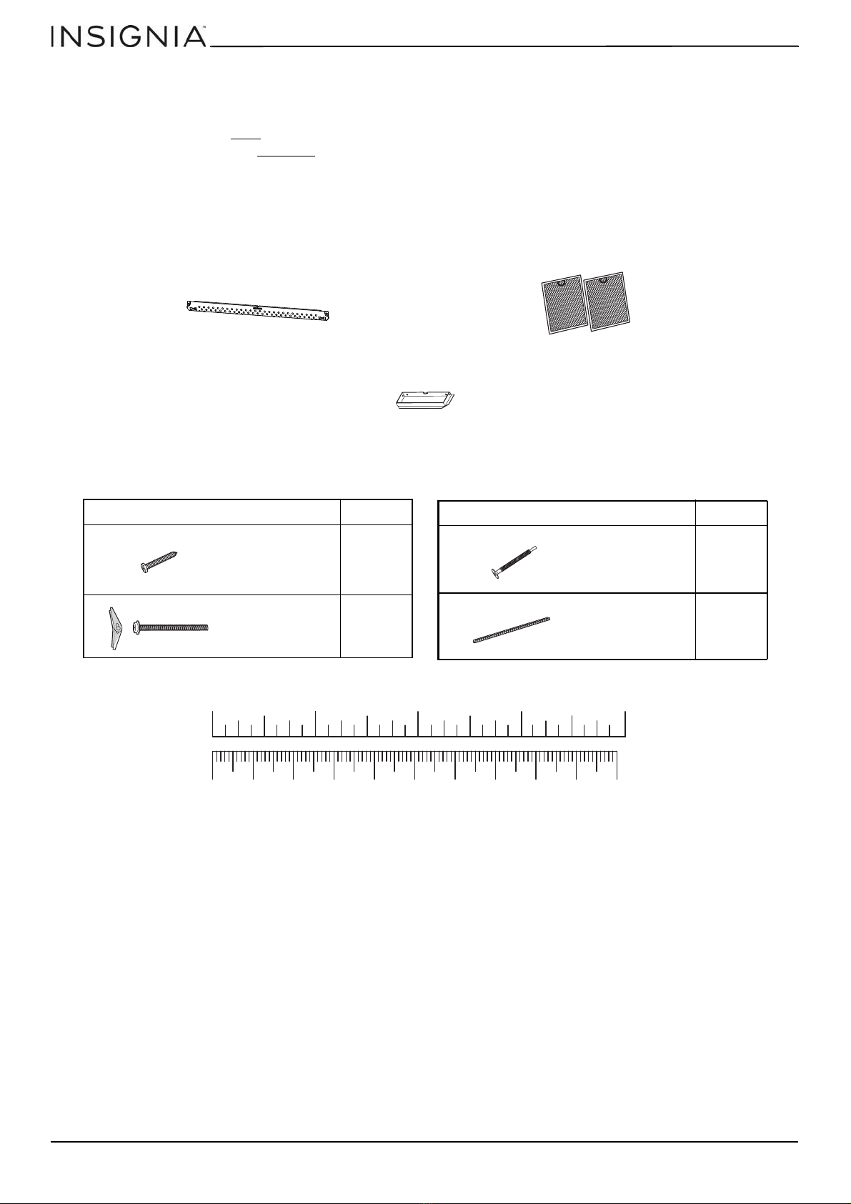
Package contents . . . . . . . . . . . . . . . . . . . . . . . . . . . . . . . . . . . . . . . . . . . . . . . . . . . . . . . . . . . . . . . . . . . . . . . . . . . . . . . . . . . . 4
Parts . . . . . . . . . . . . . . . . . . . . . . . . . . . . . . . . . . . . . . . . . . . . . . . . . . . . . . . . . . . . . . . . . . . . . . . . . . . . . . . . . . . . . . . . . . . . . . . . . . . . . . . . . . . . . 4
Hardware . . . . . . . . . . . . . . . . . . . . . . . . . . . . . . . . . . . . . . . . . . . . . . . . . . . . . . . . . . . . . . . . . . . . . . . . . . . . . . . . . . . . . . . . . . . . . . . . . . . . . . . . 4
Before you install . . . . . . . . . . . . . . . . . . . . . . . . . . . . . . . . . . . . . . . . . . . . . . . . . . . . . . . . . . . . . . . . . . . . . . . . . . . . . . . . . . . . . 5
Tools and materials needed . . . . . . . . . . . . . . . . . . . . . . . . . . . . . . . . . . . . . . . . . . . . . . . . . . . . . . . . . . . . . . . . . . . . . . . . . . . . . . . . . . . . . . 5
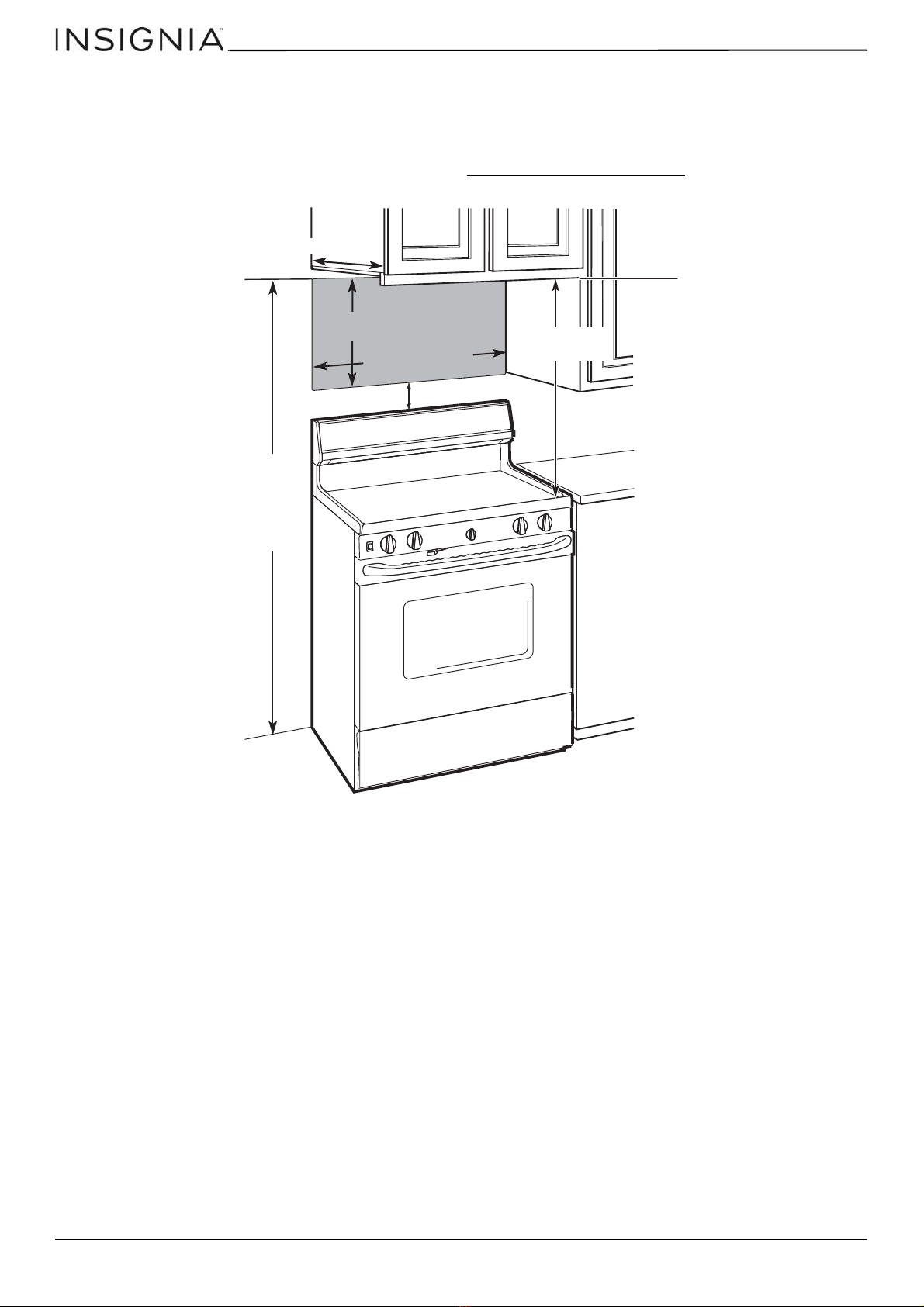
Mounting requirements . . . . . . . . . . . . . . . . . . . . . . . . . . . . . . . . . . . . . . . . . . . . . . . . . . . . . . . . . . . . . . . . . . . . . . . . . . . . . . . . . . . . . . . . . . 6
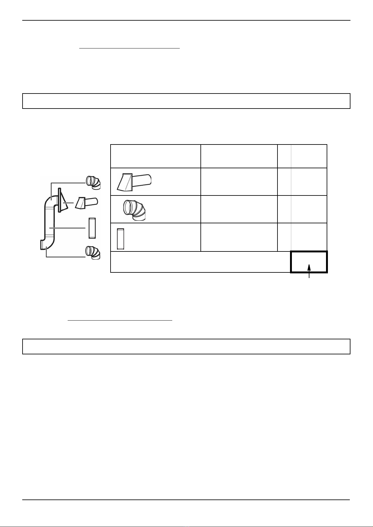
Exhaust requirements . . . . . . . . . . . . . . . . . . . . . . . . . . . . . . . . . . . . . . . . . . . . . . . . . . . . . . . . . . . . . . . . . . . . . . . . . . . . . . . . . . . . . . . . . . . . 7
Removing your microwave . . . . . . . . . . . . . . . . . . . . . . . . . . . . . . . . . . . . . . . . . . . . . . . . . . . . . . . . . . . . . . . . . . . . . . . . . . . 9
Installing your microwave . . . . . . . . . . . . . . . . . . . . . . . . . . . . . . . . . . . . . . . . . . . . . . . . . . . . . . . . . . . . . . . . . . . . . . . . . . . . 9
Step 1: Find the wall studs . . . . . . . . . . . . . . . . . . . . . . . . . . . . . . . . . . . . . . . . . . . . . . . . . . . . . . . . . . . . . . . . . . . . . . . . . . . . . . . . . . . . . . . . 9
Step 2: Align the rear wall template . . . . . . . . . . . . . . . . . . . . . . . . . . . . . . . . . . . . . . . . . . . . . . . . . . . . . . . . . . . . . . . . . . . . . . . . . . . . . . 10
Step 3: Select a ventilation type . . . . . . . . . . . . . . . . . . . . . . . . . . . . . . . . . . . . . . . . . . . . . . . . . . . . . . . . . . . . . . . . . . . . . . . . . . . . . . . . . . 12
Step 4: Option A - Attach the mounting plate to the wall . . . . . . . . . . . . . . . . . . . . . . . . . . . . . . . . . . . . . . . . . . . . . . . . . . . . . . . . . 13
Step 5: Option A - Preparing the top cabinet . . . . . . . . . . . . . . . . . . . . . . . . . . . . . . . . . . . . . . . . . . . . . . . . . . . . . . . . . . . . . . . . . . . . . 15
Step 6: Option A - Adapt the microwave blower for outside top exhaust . . . . . . . . . . . . . . . . . . . . . . . . . . . . . . . . . . . . . . . . . . 17
Step 7: Option A - Mount the microwave . . . . . . . . . . . . . . . . . . . . . . . . . . . . . . . . . . . . . . . . . . . . . . . . . . . . . . . . . . . . . . . . . . . . . . . . . 19
Step 8: Option A - Connecting ductwork . . . . . . . . . . . . . . . . . . . . . . . . . . . . . . . . . . . . . . . . . . . . . . . . . . . . . . . . . . . . . . . . . . . . . . . . . 21
Step 4: Option B - Cutting a vent opening . . . . . . . . . . . . . . . . . . . . . . . . . . . . . . . . . . . . . . . . . . . . . . . . . . . . . . . . . . . . . . . . . . . . . . . . 22
Step 5: Option B - Attach the mounting plate to the wall . . . . . . . . . . . . . . . . . . . . . . . . . . . . . . . . . . . . . . . . . . . . . . . . . . . . . . . . . . 23
Step 6: Option B - Preparing the top cabinet . . . . . . . . . . . . . . . . . . . . . . . . . . . . . . . . . . . . . . . . . . . . . . . . . . . . . . . . . . . . . . . . . . . . . . 25
Step 7: Option B - Adapt the microwave blower for outside back exhaust . . . . . . . . . . . . . . . . . . . . . . . . . . . . . . . . . . . . . . . . . 27
Step 8: Option B - Mount the microwave . . . . . . . . . . . . . . . . . . . . . . . . . . . . . . . . . . . . . . . . . . . . . . . . . . . . . . . . . . . . . . . . . . . . . . . . . 30
Step 4: Option C - Attach the mounting plate to the wall . . . . . . . . . . . . . . . . . . . . . . . . . . . . . . . . . . . . . . . . . . . . . . . . . . . . . . . . . . 32
Step 5: Option C - Preparing the top cabinet . . . . . . . . . . . . . . . . . . . . . . . . . . . . . . . . . . . . . . . . . . . . . . . . . . . . . . . . . . . . . . . . . . . . . 34
Step 6: Option C - Mount the microwave . . . . . . . . . . . . . . . . . . . . . . . . . . . . . . . . . . . . . . . . . . . . . . . . . . . . . . . . . . . . . . . . . . . . . . . . . 36
Before using your microwave . . . . . . . . . . . . . . . . . . . . . . . . . . . . . . . . . . . . . . . . . . . . . . . . . . . . . . . . . . . . . . . . . . . . . . . . 38
Template dimensions . . . . . . . . . . . . . . . . . . . . . . . . . . . . . . . . . . . . . . . . . . . . . . . . . . . . . . . . . . . . . . . . . . . . . . . . . . . . . . . 39
Rear wall template dimensions . . . . . . . . . . . . . . . . . . . . . . . . . . . . . . . . . . . . . . . . . . . . . . . . . . . . . . . . . . . . . . . . . . . . . . . . . . . . . . . . . . 39
Top cabinet template dimensions . . . . . . . . . . . . . . . . . . . . . . . . . . . . . . . . . . . . . . . . . . . . . . . . . . . . . . . . . . . . . . . . . . . . . . . . . . . . . . . 40
Obtaining replacement parts . . . . . . . . . . . . . . . . . . . . . . . . . . . . . . . . . . . . . . . . . . . . . . . . . . . . . . . . . . . . . . . . . . . . . . . . 41
Specifications . . . . . . . . . . . . . . . . . . . . . . . . . . . . . . . . . . . . . . . . . . . . . . . . . . . . . . . . . . . . . . . . . . . . . . . . . . . . . . . . . . . . . . . 41
Legal notices . . . . . . . . . . . . . . . . . . . . . . . . . . . . . . . . . . . . . . . . . . . . . . . . . . . . . . . . . . . . . . . . . . . . . . . . . . . . . . . . . . . . . . . . 41
ONE-YEAR LIMITED WARRANTY . . . . . . . . . . . . . . . . . . . . . . . . . . . . . . . . . . . . . . . . . . . . . . . . . . . . . . . . . . . . . . . . . . . . . . 41
Introduction3

3
NS-OTRC15SS9
www.insigniaproducts.com
1.5 Cu. Ft. Over-the-Range Convection
Microwave
Introduction
Congratulations on your purchase of a high-quality Insignia product. Your NS-OTRC15SS9 represents the state of the art in
microwave design and is designed for reliable and trouble-free performance.
This installation guide will show you how to install your new over-the-range microwave.
BEFORE YOU BEGIN
Read these instructions completely and carefully.
• IMPORTANT – Save these instructions for local inspector’s use.
• IMPORTANT – Observe all governing codes and ordinances.
• Note to Installer – Be sure to leave these instructions with the consumer.
• Note to Consumer – Keep these instructions for future reference.
• Skill level – Installation of this appliance requires basic mechanical and electrical skills.
• Proper installation is the responsibility of the installer.
• Product failure due to improper installation is not covered under the warranty.
IMPORTANT SAFETY INSTRUCTIONS
IMPORTANT–PLEASE READ CAREFULLY. FOR PERSONAL SAFETY, THIS APPLIANCE MUST BE PROPERLY GROUNDED TO
AVOID SEVERE OR FATAL SHOCK.
This product requires a three-prong, properly grounded outlet for safe operation. If
not properly grounded, or if the outlet box does not meet the electrical requirements
noted (under ELECTRICAL REQUIREMENTS), a qualified electrician should be
employed to correct any deficiencies.
The power cord of this appliance is equipped with a three-prong (grounding) plug
which mates with a standard three-prong (grounding) wall receptacle to minimize the
possibility of electric shock hazard from this appliance.
You should have the wall receptacle and circuit checked by a qualified electrician to
make sure that the receptacle is properly grounded.
Where a standard two-prong wall receptacle is encountered, it is very important to have it replaced with a properly
grounded three-prong wall receptacle installed by a qualified electrician.
DO NOT, UNDER ANY CIRCUMSTANCES, CUT, DEFORM, OR REMOVE ANY OF THE PRONGS FROM THE POWER CORD. DO
NOT USE WITH AN EXTENSION CORD.
Caution
For personal safety, remove the house fuse or open the circuit breaker before beginning
installation to avoid severe or fatal shock injury.
For personal safety, the mounting surface must be capable of supporting a total weight of 113–
135 pounds (51.3–61.2 kg). This includes the cabinet load, weight of the microwave, and
additional oven loads.
For personal safety, this product cannot be installed in cabinet arrangements such as an island or
a peninsula. It must be mounted to BOTH a top cabinet AND a wall.
ELECTRICAL REQUIREMENTS
The product rating of your microwave is 120 volts AC, 60 Hertz, 15 amps, and 1.6 kilowatts. This
product must be connected to a supply circuit of the proper voltage and frequency. Wire size
must conform to the requirements of the National Electrical Code or the prevailing local code for this kilowatt rating. The
power supply cord and plug should be brought to a separate 15- to 20- ampere branch circuit single grounded outlet. The
outlet box should be located in the cabinet above the microwave oven. The outlet box and supply circuit should be
installed by a qualified electrician and conform to the National Electrical Code or the prevailing local code.
Note: For easier installation and personal safety, it is recommended that two people install this product.
Ensure
proper
ground
before use

www.insigniaproducts.com
4
1.5 Cu. Ft. Over-the-Range Convection Microwave
Package contents
• 1.5 cu. ft. over-the-range convection microwave
• Turntable (with ring)
• Installation parts (see “Parts” below)
• Installation hardware (see “Hardware” below)
• Mounting templates (2)
• Installation Guide
•User Guide
Parts
Make sure that you have all the parts necessary to install your new microwave.
Hardware
Mounting plate
(ships attached to microwave)
Exhaust adapter
Grease filters (Qty. 2)
Hardware Qty.
2
2
Wood screws
(1/4” × 2”)
Toggle bolts with
wing nuts
(3/16” × 3”)
Hardware Qty.
3
1
Self-aligning
machine screws
(1/4” × 3-1/4”)
Nylon grommet
(for metal cabinets)
10 20 30 40 50 60 70 80 90 100mm
1234in

5
NS-OTRC15SS9
www.insigniaproducts.com
Before you install
Read these instructions completely before installing your microwave. Make sure that your space meets the mounting
requirements and that you’ve gathered all needed tools and materials.
Tools and materials needed
#1 Phillips screwdriver
Pencil
Tin snips
(to cut damper, if needed)
Scissors
(to cut template, if needed)
Gloves
Safety goggles
Saw
(saber, hole, or keyhole)
Ruler or tape measure
Electric drill with 3/16”, 1/2”, and 5/8” bits
Edge-to-edge stud finder
Level
Duct tape
Filler blocks or scrap wood pieces
(for top cabinet spacing in recessed
bottom cabinet installations, if needed)
Carpenter square
(optional)
Ducts (if venting outside)
See “Exhaust requirements” on page 7

www.insigniaproducts.com
6
1.5 Cu. Ft. Over-the-Range Convection Microwave
Mounting requirements
• The space between the cabinets must be 30 in. (76.2 cm) wide. If the space between the cabinets is more than 30 in.
(76.2 cm), you’ll need filler material to fill the gap between the microwave and cabinets.
• This microwave is for installation over ranges up to 36 in. (91.4 cm) wide.
• If installing the microwave beneath smooth, flat cabinets, make sure that you leave enough space for the power cord.
• If you are going to vent your exhaust to the outside, see “Exhaust requirements” on page 7 for exhaust duct
preparation.
66 in. (167.6 cm) or more
from the floor to the top
of the microwave
16-1/2 in.
(41.9 cm)
30in.(76.2cm)
30 in.
(76.2 cm)
2 in. (5.1 cm)
Bottom edge of
the cabinet must
be 30 in. (76.2 cm)
or more from the
cooking surface.
13 in. (33 cm) max.

7
NS-OTRC15SS9
www.insigniaproducts.com
Exhaust requirements
Use this section if you plan to vent your microwave outside (top or back exhaust). If you plan to recirculate the air back into
the room, skip to “Removing your microwave” on page 9.
When installing exhaust vents:
• Use the most direct route with as few elbows/transitions as possible. This helps prevent blockages and ensures that the
exhaust is being vented correctly.
• Your microwave is designed to mate with a standard 3-1/4” × 10” rectangular duct. If a round duct is required, a
rectangular-to-round transition adapter must be used with 6” (15.2 cm) or 5” (12.7 cm) diameter round ducts.
• Elbows, transitions, and wall/roof caps add resistance to airflow. Each of these pieces are equivalent to a section of
straight duct that is longer than their actual physical size. When calculating your duct length, add the equivalent
lengths of all the pieces together. For proper airflow, the equivalent airflow should not exceed 120 ft. For example:
Note: If a rectangular-to-round transition adapter is used, you must cut the bottom corners of the damper with tin snips to let the damper
have free movement.
Note: Equivalent lengths of duct pieces are based on actual tests and reflect requirements for good venting performance with any vent
hood.
EXAMPLE
Duct Pieces Equivalent
Length ×Number
Used =Total
Equivalent
Length
40 ft. ×(1)=40ft.
10 ft. ×(2)=20ft.
3 ft. ×(1)=3ft.
Total ductwork =63ft.
Roof cap
90° elbow
Straight duct 6” round
OR
3-1/4” × 10” rectangular
For proper
airflow, this
number should
not exceed
120 ft.
Use the “Equivalent duct length table” on page 8 to calculate the equivalent ductwork length for your setup.
Example setup:

www.insigniaproducts.com
8
1.5 Cu. Ft. Over-the-Range Convection Microwave
Equivalent duct length table
To calculate your equivalent duct length:
1Write the number of sections used for each of the duct pieces.
2Multiply the number used by the equivalent length for each duct piece.
3Add the total equivalent lengths together. This number must be less than 120 ft.
Duct Pieces Equivalent
Length ×NumberUsed=
Total
Equivalent
Length
5 ft. × ()
=ft.
40 ft. ×()
=ft.
10 ft. × ()
=ft.
5 ft. × ()
=ft.
25 ft. ×()
=ft.
5 ft. × ()
=ft.
24 ft. × ()
=ft.
1 ft. × ()
=ft.
Total ductwork =
ft.
(For proper airflow,
this number should
not exceed 120 ft.)
Rectangular-to-
round transition adapter
Wall cap
90° elbow
45° elbow
90° elbow
45° elbow
Roof cap
Straight duct 6” round
OR
3-1/4” × 10” rectangular

9
NS-OTRC15SS9
www.insigniaproducts.com
Removing your microwave
1Remove the instructions, filters, glass turntable, and the hardware bag. Do not remove the Styrofoam protecting the
front of the microwave.
2Fold back all four carton flaps against the sides of the box, then carefully roll the oven and carton over onto the top
side.
3Pull the box off the microwave.
Installing your microwave
Step 1: Find the wall studs
1Using an edge-to-edge stud finder, locate the edges of the wall stud(s) within the opening.
2Mark the center of each stud, and then draw a vertical line down the center of each stud.
Warning: Your microwave must be connected to at least one wall stud.
Note: The center of any adjacent wall studs should be 16" or 24" from this mark.
You’ll need:
Box
Styrofoam
Wall
stud
Center of the
wall stud
Pencil
Ruler or tape measure
Edge-to-edge stud finder

www.insigniaproducts.com
10
1.5 Cu. Ft. Over-the-Range Convection Microwave
Step 2: Align the rear wall template
1Use a level to make sure that the bottom of the cabinet is level.
2Draw a vertical line down the center of the wall in the mounting space. This is where the center of your template will be.
3Draw a horizontal line at the height of the front of your cabinet. This is where the top of your template will be. If the
bottom of your cabinet is flat, make sure that you leave space for the power cord.
4Trim the rear wall template along the dotted line.
5Tape the template in place so that it is centered on the vertical line and the top edge is aligned with the horizontal line.
6Find a hole that aligns with a stud (this is C or D on the template).
Note: If the rear wall template is damaged or unusable, measure and mark the wall with the dimensions at the end of this step.
Notes:
• If installing the microwave beneath smooth, flat cabinets, make sure that you leave enough space for the power cord.
• If cabinets have decorative trim that interferes with the microwave installation, remove the trim to install the microwave properly and to
make sure that it is level.
Warning: You must mount to at least one stud.
Rear wall template
Cabinet
WALL
Flat bottom: Front overhang: Framed:
Cabinet Cabinet
Power cord Power cord Power cord
WALL
WALL
Rear wall template Rear wall template
Vertical line in the center
Top of the template aligned
with the horizontal line

11
NS-OTRC15SS9
www.insigniaproducts.com
7Drill holes through the template at points A, B, and C or D. If the hole lines up with a stud, drill a 3/16” hole. Otherwise,
drill a 5/8” hole for the toggle bolts. You must use at least three holes for mounting.
You’ll need:
Note: Depending on your stud locations, your installation may look
different. You must mount to at least one stud.
Rear wall template
Pencil
Duct tape
Electric drill with 3/16” and 5/8” bits
Level
Ruler or tape measure

www.insigniaproducts.com
12
1.5 Cu. Ft. Over-the-Range Convection Microwave
Step 3: Select a ventilation type
This microwave is designed for three types of ventilation. Select the type of ventilation you want to use, then go to the
corresponding page.
Option A - Outside top exhaust (vertical duct): See page 13
Option B - Outside back exhaust (horizontal duct): See page 22
Option C - Recirculating (non-vented/ductless): See page 32
Note: This microwave is shipped assembled for recirculation.
Note: If a wall stud is within
6 in. (15.2 cm) of the vertical
center line, you cannot use
this installation option.
Note: Requires a
charcoal filter
(included)

13
NS-OTRC15SS9
www.insigniaproducts.com
Step 4: Option A - Attach the mounting plate to the wall
1Remove the rear wall template.
2Remove the mounting plate from the back of your microwave using a #1 Phillips screwdriver. Replace the two screws
back into the microwave after removing the mounting plate.
3Insert the toggle bolt(s) through the front of the mounting plate into the hole(s) that are not going into a stud, and
then attach the toggle wings ¾" (1.9 cm) onto each bolt. Hold your mounting plate up to the holes in your wall to
identify the correct position.
4Place the mounting plate against the wall and insert the toggle wings into the holes you drilled in the drywall. Pull the
mounting plate away from the wall to help tighten the toggle wings.
Note: The top of the mounting plate is indicated with an arrow. The mounting plate’s hooks are on the front.
Note: Depending on
your stud locations,
your installation may
look different. You
should insert toggle
bolts into drywall and
wood screws into
studs.
Bolt Wing
Mounting plate

www.insigniaproducts.com
14
1.5 Cu. Ft. Over-the-Range Convection Microwave
5Insert wood screw(s) through the mounting plate and into the hole(s) drilled in the stud(s), then tighten both the wood
screw(s) and toggle bolt(s) with a Phillips screwdriver to mount the plate. Make sure that the plate is centered before
tightening fully.
Caution: Be careful to avoid pinching your fingers between the back of the mounting plate and the wall.
You’ll need:
Mounting plate
Wall
Toggle wing
Toggle bolt
Wood screws
Mounting plate
(ships attached to microwave)
Toggle bolts
Phillips screwdrivers

15
NS-OTRC15SS9
www.insigniaproducts.com
Step 5: Option A - Preparing the top cabinet
You need to drill holes for the top support screws, a hole large enough for the power cord to fit through, and a cutout large
enough for the exhaust adapter.
1Turn off the power to the outlet in the cabinet.
2Remove everything from the cabinet.
3Trim the Top Cabinet Template along the dotted line.
4If the bottom of your cabinet is recessed and the template is too large, trim the edges to fit. Your template should fit
snugly inside the space with no overhang.
5To position the Top Cabinet Template:
• Align the center line on the template with the center line that you drew on the wall.
• Align the back edge of the template to the rear wall (smooth or flat bottom cabinets) or to the back of the recess
(recessed cabinets) to make sure that the holes cut into the upper cabinet align with the holes in the top of the
microwave.
6Tape the template to the bottom of the cabinet.
7Drill 3/8" holes through the template at points A,B, and C.
8Cut a 2" (5 cm) diameter hole at point Dfor the power cord.
9Cut out the shaded area Ethrough the cabinet bottom.
Notes:
• Make sure that you keep the left and right sides even. For example, if you need to trim the sides by 1" (2.5 cm), cut 1/2" (1.25 cm) from the
left side and 1/2" (1.25 cm) from the right side.
• Some cabinets have a small bracket or glue block between the overhang and the underside of the cabinet bottom. Cut the template to
fit around these so it lies flat on the bottom of the cabinet.
Caution: Wear safety goggles when drilling holes in the cabinet bottom.
Center line

www.insigniaproducts.com
16
1.5 Cu. Ft. Over-the-Range Convection Microwave
10 If you have recessed cabinets:
• Make two filler blocks out of scrap wood pieces the size of shaded areas H(about 2.25 × 4.125 in. or 5.7 × 10.5 cm).
They must be as thick as the depth of the cabinet recess.
• Drill 5/8" holes in the filler blocks to align with points A and B.
• Align the blocks with the corresponding holes in the cabinet. They should be at the same level as the bottom edge of
the cabinet frame.
11 Remove the template.
You’ll need:
Filler blocks
Electric drill with 1/2” and
5/8” bits
Duct tape Scissors
(recessed cabinets only)
Safety goggles
Saw
(saber, hole, or keyhole)
Ruler or tape measure Filler blocks or scrap wood pieces
(for recessed cabinets only)
Top Cabinet Template

17
NS-OTRC15SS9
www.insigniaproducts.com
Step 6: Option A - Adapt the microwave blower for outside top exhaust
1Remove and save the two screws that hold the blower plate and blower motor to the microwave.
2Carefully pull out the blower motor. The wires will extend far enough to let you adjust the blower unit. Do not
disconnect the wires.
3Turn the blower unit 90° so that the fan blade openings are facing out the top of the microwave.
4Place the blower motor back into the opening. The blower unit exhaust openings should match the exhaust openings
on the top of the microwave.
Caution: Do not pull or stretch the blower unit wiring. Make sure that the wires are not pinched.
Blower plate
Back of microwave
Blower motor screw
Blower plate screw
Back of microwave
BEFORE
AFTER
Fan blade openings facing the top

www.insigniaproducts.com
18
1.5 Cu. Ft. Over-the-Range Convection Microwave
5Secure the blower motor and blower plate to the microwave with the two screws that you previously removed.
6Slide the exhaust adapter into the guides on the top of the blower plate and push in until it is secure in the locking tabs.
7Remove any tape securing the damper and make sure that the damper pivots easily. You may need to adjust the
exhaust adapter to fit with your house’s exhaust duct after the microwave is installed.
You’ll need:
Blower plate screw
Blower motor screw
Exhaust adapter
Guides
Locking tab
Damper
Back of microwave
Exhaust adapter
Blower plate
Phillips screwdrivers Exhaust adapter

19
NS-OTRC15SS9
www.insigniaproducts.com
Step 7: Option A - Mount the microwave
1If your cabinet is metal, insert the nylon grommet into the power cord hole to prevent cutting the cord.
2Lift the microwave, tilt it forward, and hook the slots on the back bottom edge onto the four lower tabs of the
mounting plate. Rotate the front of the microwave up against the bottom of the cabinet.
3Insert a self-aligning screw through the top, center cabinet hole and temporarily secure the microwave by turning the
screw at least two full turns (it will be fully tightened later).
4Insert two self-aligning screws through the outer top cabinet holes, securing each screw with at least two full turns.
5While holding the microwave up against the wall and cabinet, fully tighten the three screws.
Caution:
• For easier installation and personal safety, we recommend that two people install this microwave oven.
• Do not grip or use the handle during installation.
• To keep the power cord tight while mounting the microwave oven, thread the power cord through the hole in the bottom of the
cabinet.
Notes:
• We recommend using filler blocks if the front of the cabinet hangs below the cabinet’s bottom shelf.
• If filler blocks are not used, damage may occur from over-tightening the screws.
• Be sure to keep the power cord tight.
• Do not pinch the cord, especially when mounting flush to the bottom of the cabinet.
Thread the power cord through the
cable hole in the top cabinet. Keep it
tight throughout steps 1-2.
Front of cabinet
Bottom of cabinet
Filler block (optional)
Self-aligning machine screw
Top of microwave
Equivalent to depth of cabinet recess

www.insigniaproducts.com
20
1.5 Cu. Ft. Over-the-Range Convection Microwave
6Fit the two grease filters into the openings underneath your microwave.
You’ll need:
BOTTOM
Nylon grommet
(for metal cabinets) Self-aligning machine
screws Grease filters
Phillips screwdrivers
Other manuals for NS-OTRC15SS9
1
Table of contents
Other Insignia Microwave Oven manuals

Insignia
Insignia NS-OTR16WH9 User manual

Insignia
Insignia NS-OTR16SS8Q User manual

Insignia
Insignia NS-MW11BK0 User manual

Insignia
Insignia NS-7CM6-WH User manual

Insignia
Insignia NS-OTR16WH8 User manual

Insignia
Insignia NS-MW09BK0-C User manual

Insignia
Insignia NS-MWR07R2 User manual

Insignia
Insignia NS-OTRC15SS9 User manual

Insignia
Insignia NS-MW07WH0 User manual

Insignia
Insignia NS-OTR16SS8Q User manual