Inspur NF5288M5 User manual

Inspur Yitian Supercomputer
User Manual
NF5288M5

© Copyright Inspur 2017. All rights reserved.
No part of this document may be reproduced or transmitted in any form or by any means
without prior written consent of Inspur.
The information in this manual is subject to change without notice.
Inspur is the registered trademark of Inspur. All the other trademarks or registered
trademarks mentioned in this manual are the property of their respective holders.
Edition: 1.0
Dec 2017

Abstract
This manual contains technical information such as specifications, hardware operations,
software configuration, fault diagnosis, etc. that are relevant to the maintenance and
operation of this server.
It is recommended that server installation, configuration, and maintenance is performed by
experienced technicians only.
Target Audience
This manual is intended for:
●Technical support engineers
●Product maintenance engineers
●Technicians
Warnings:
This manual introduces the NF5288M5 server’s technical features, system installaon
and setup, which will help the user to understand how best to ulize the server and all its
funconalies.
1. For your safety, please do not disassemble the server’s components arbitrarily. Please do
not extend conguraon or connect other peripheral devices arbitrarily. If needed, please
contact Inspur for our support and guidance.
2. Before disassembling the server’s components, please be sure to disconnect all the power
cords connected to the server.
3. BIOS and BMC setup is a signicant factor in correctly conguring your server. If there
are no special requirements, it is suggested to use the Default Values and not alter the
parameter sengs arbitrarily. Aer the rst login, please change the BMC user password in
me.
4. Please install the product-compable operang system and use the driver provided by
Inspur. If you use an incompable operang system or non-Inspur driver , it may cause
compability issues and aect the normal use of the product, Inspur will not assume any
responsibility or liability.
Inspur is not responsible for any damages, including loss of prots, loss of informaon,
interrupon of business, personal injury, and/or any damage or consequenal damage
without limitaon, incurred before, during, or aer the use of our products.

Contents
1 Safety Instructions......................................................................................................................... 1
2 Product Specification..................................................................................................................... 6
2.1 Introduction................................................................................................................................ 6
2.2 Features and Specifications........................................................................................................ 7
3 Component Identification ............................................................................................................. 9
3.1 Front Panel Components ........................................................................................................... 9
3.2 Rear Panel Components ............................................................................................................. 10
3.3 Motherboard Components......................................................................................................... 11
4 Operations..................................................................................................................................... 13
4.1 Power up the Server................................................................................................................... 13
4.2 Power down the Server.............................................................................................................. 13
4.3 Extend the Server from the Rack............................................................................................... 13
4.4 Remove the Access Panel ........................................................................................................... 14
4.5 Install the Access Panel .............................................................................................................. 16
4.6 Remove the PCIE Riser Cage....................................................................................................... 16
4.7 Install the PCIE Riser Cage .......................................................................................................... 17
4.8 Remove the Air Baffle................................................................................................................. 17
5 Setup ............................................................................................................................................. 19
5.1 Optimum Environment............................................................................................................... 19
5.2 Rack Warnings ............................................................................................................................ 22
5.3 Identifying the Contents of the Server Shipping Carton.............................................................22
5.4 Installing Hardware Options ....................................................................................................... 22
5.5 Installing the Server into the Rack.............................................................................................. 23
5.6 Installing the Operating System.................................................................................................. 23
6 Hardware Options Installation....................................................................................................... 24
6.1 Introduction................................................................................................................................ 24
6.2 Processor Option........................................................................................................................ 24

6.3 Memory Option.......................................................................................................................... 26
6.4 Hot-plug HDD Option ................................................................................................................. 28
6.5 Redundant Hot-plug Power Supply Option ................................................................................ 29
6.6 Expansion Board Option............................................................................................................. 30
6.7 M.2 Memory Card Option .......................................................................................................... 32
6.8 Air Baffle Option......................................................................................................................... 33
6.9 Cache Supercapacitor Option..................................................................................................... 34
7 BIOS Setup..................................................................................................................................... 35
7.1 Common Operations .................................................................................................................. 35
7.2 BIOS Parameter Description ....................................................................................................... 36
7.3 Firmware Update........................................................................................................................ 68
8 BMC Settings ................................................................................................................................ 70
8.1 Introduction................................................................................................................................ 70
8.2 Functional Modules.................................................................................................................... 71
8.3 Web Interface Introduction ........................................................................................................ 72
8.4 Storage ....................................................................................................................................... 79
8.5 Remote Control .......................................................................................................................... 77
8.6 Power and Fan............................................................................................................................ 78
8.7 BMC Settings .............................................................................................................................. 81
8.8 Logs ............................................................................................................................................ 84
8.9 Fault Diagnosis............................................................................................................................ 87
8.10 System Maintenance ................................................................................................................ 88
8.11 Command Line Introduction..................................................................................................... 91
8.11 Time Zone Table ....................................................................................................................... 96
9 Common Faults, Diagnosis and Troubleshooting .......................................................................... 99
9.1 Hardware Problems.................................................................................................................... 99
9.2 Software Problems ..................................................................................................................... 102
10 Battery Replacement................................................................................................................... 104
11 Regulatory Compliance Notices................................................................................................... 105

11.1 Chinese Notice.......................................................................................................................... 105
11.2 Battery Replacement Notice .................................................................................................... 105
12 Electrostatic Discharge ................................................................................................................ 106
12.1 Preventing Electrostatic Discharge ........................................................................................... 106
12.2 Grounding Methods to Prevent Electrostatic Discharge ..........................................................106
13 Warranty...................................................................................................................................... 107
13.1 Introduction.............................................................................................................................. 107
13.2 Warranty Service ...................................................................................................................... 107
13.3 Warranty Exclusions ................................................................................................................. 108

1
Safety Introduction
1 Safety Instructions
WARNING: Please be advised to follow the instructions below for safety. Failure to do so
could result to potential dangers that may cause property loss, personal injury or death.
1. The power supplies in the system may produce high voltages and energy hazards that
may cause personal injury. For your safety, please do not attempt to remove the cover
of the system to remove or replace any component without assistance provided by
Inspur. Only service technicians trained by Inspur are authorized to remove the cover of
the host, and to remove and replace internal components.
2. Please connect the equipment to the appropriate power supply. Use only power
supplies with the correct voltage and electrical specifications according to the label. To
protect your equipment from damages caused by a momentary spike or plunge of the
voltage, please use relevant voltage stabilizing equipment, or uninterruptible power
supplies.
3. If you must use an extension cable, please use a three-core cable with properly
grounded plugs. Observe extension cable ratings. Ensure that the total rating of all
equipment plugged into the extension cable does not exceed 80 percent of the ratings
limit for the extension cable.
4. Please be sure to use the power supply components that come with the server, such as
power lines, power socket (if provided with the server) etc. For your safety, please do
not replace power cables or plugs randomly.
5. To prevent electric shock dangers caused by leakage in the system, please make sure
that the power cables of the system and peripheral equipment are correctly connected
to the earthed/grounded power socket. Please connect the three-core power line plug
to the three-core AC power socket that is well earthed and easy to access. Be sure
to use earthing /grounding pin of power lines and do not use the patch plug or the
earthing/grounding pin unplugged with cables. In the case that the earthing/grounding
conductors are not installed and it is uncertain whether there are appropriate earthing/
grounding protections, please do not use or attempt to operate the equipment. Contact
and consult an electrician.
6. Please do not push any objects into the openings of the system. Doing so may cause
fire or electric shock.

2
7. Please place the system far away from the cooling plate and heat sources, and be sure
not to block the air vents.
8. Please be sure not to scatter food or liquid in the system or on other components, and
do not use the product in humid or dusty environments.
9. Using an incompatible battery may cause explosion. When battery replacement is
required, please consult the manufacturer first, and choose batteries of the same or
equivalent type. Do not disassemble, crush, puncture the batteries or make the external
connection point short circuit, and do not expose them in the environment over 60°C.
Never throw batteries into fire or water. Please do not attempt to open or repair the
batteries. Dispose of used batteries according to instructions. For battery recycling,
please contact the local waste recycling center.
10. Before installing equipment into the rack, please install all front and side stabilizers on
the independent rack first. Please install the front stabilizers first, if connecting with
other racks. Please install stabilizers before installing equipment into the rack. Failure to
install the corresponding stabilizers before installing equipment into the rack may cause
the cabinet to tip over, possibly resulting to severe injury. After installing the equipment
and other components into the rack, only one component can be pulled out from the
rack through its sliding part at one time. Pulling out several components at the same
time may cause the rack to turn over, resulting to serious personal injury.
11. A minimum of two people are required to safely move a rack. The racks are extremely
awkward and heavy, moving them without adequate, trained personnel could result in
severe injury or death.
12. It is prohibited to directly short-circuit the copper busbar. Please do not touch the
copper busbar when the rack is powered on.
13. This is Class A product, and may cause radio interference. In such case, users may need
to take necessary measures to mitigate the interference.
14. The equipment is intended for installation in a Restricted Access Location.
Note: The following considerations may help avoid the occurrence of problems that could
damage the components or cause data loss, etc.
1. In the event of the following, please unplug the power line plug from the power socket
and contact Inspur’s customer service department:

3
Safety Introduction
1) The power cables, extension cables or power plugs are damaged.
2) The products get wet.
3) The products have fallen or have been damaged.
4) Other objects have fallen into the products.
5) The products do not or are unable to function normally even when attempting to
operate according to the instructions.
2. If the system becomes wet or damp, please follow these steps:
1) Power off the equipment, disconnect them with the power socket, wait for 10 to 20
seconds, and then open the host cover.
2) Move the equipment to a well-ventilated place to dry the system at least for 24 hours
and make sure that the system is fully dried.
3) Close the host cover, reconnect the system to the power socket, and then power on.
4) In case of operation failure or other abnormal situations, please contact Inspur and get
technical support.
3. Pay attention to the position of system cables and power cables-avoid placing wires in
high foot traffic locations. Please do not place objects on the cables.
4. Before removing the host cover, and/or touching the internal components, please
allow for the equipment to cool first. To avoid damaging the mainboard, please power
off the system and wait for five seconds, and then remove the components from the
mainboard and/or disconnect the peripheral device from the system. Please remember
that only service technicians trained by Inspur are authorized to remove the cover of
the host, and to remove and replace internal components.
5. If there is modem, telecom or LAN options installed in the equipment, please pay
attention to the followings:
1) In the case of thunder and lightning, please do not connect or use the modem.
2) Never connect or use the modem in a damp environment.
3) Never insert the modem or telephone cables into the socket of network interface
controller (NIC).
4) Before unpacking the product package, installing internal components, touching
uninsulated cables or jacks of the modem, please disconnect the modem cables.
6. In order to prevent electrostatic discharge from damaging the electronic components in
the equipment, please pay attention to the followings:
1) Please remove any static electricity on your body before dismounting or touching

4
any electronic component in the equipment, to prevent the static electricity from
conducting itself to the sensitive components. You may remove the static electricity on
the body by touching the metal earthing objects (such as the unpainted metal surface
on the rack).
2) Please do not take electrostatic sensitive components that are not ready to be installed
for application out of the antistatic package materials.
3) While working, please touch the earthing conductor or the unpainted metal surface on
the cabinet regularly to remove any static electricity from the body that may damage
the internal components.
7. Upon receiving the proper authorization from Inspur and dismounting the internal
components, please pay attention to the following:
1) Switch the system power supply off and disconnect the cables, including all connections
of the system. When disconnecting the cables, please hold the connector of the cables
and slowly pull the plugs out. Never pull on the cables.
2) The products need to completely cool down before dismounting the host cover or
touching the internal components.
3) During the dismounting process, avoid making large movement ranges to prevent
damage to the components or scratching arms.
4) Handle components and plug-in cards with care. Please do not touch the components
or connection points on the plug-in cards. When handling the plug-in cards or
components, firmly grab the edges of the plug-in cards and components, and/or their
metal fixed supports.
8. During the process of rack installation and application, please pay attention to the
followings:
1) After the rack installation is finished, please ensure that the stabilizers have been fixed
to the rack and supported to ground, and the weight of the rack is firm on ground.
2) Always load from the bottom up, and load the heaviest items first.
3) When pulling out the components from the rack, apply slight force to keep the rack
balanced.
4) When pressing down the release latch and the rail of components is sliding, please be
careful; as the sliding may hurt your fingers.
5) Do not overload the AC power supply branch circuits in the rack. The total load of the
rack should not exceed 80% of the ratings of the branch circuits.

5
Safety Introduction
6) Ensure that components in the rack have good ventilation conditions.
7) When repairing components in the rack, never step on any other components.

6
2 Product Specification
2.1 Introduction
Inspur Yian NF5288M5 (AGX-2) is a high-end, dual-socket and rack-mounted server, which
is designed based on the new generaon of Intel® Xeon® scalable processor, to sasfy the
requirements of cloud compung, big data, data mining, deep learning and other high-end
IT applicaons. This server has high quality and high reliability on the performance, storage
and extension, and makes innovaons and breakthroughs on compung performance,
exible conguraon and intelligent management, parcularly suitable for telecom
operators, nancial industry, internet companies and other large-scale enterprises.
●Main features:
◆Excellent computing, storage and scalability
Supports a new generation of Intel® Xeon® scalable processors, supports TDP165 CPU;
16 DIMMs support RDIMM, LRDIMM, NVDIMM memory, 4 x Apache Pass, significantly
improved application performance and computing performance.
Achieves mul-dimensional space extension, supports 8 2.5” hard drives in 2U space.
◆ Optimize for different applications
Storage modules, I/O modules, network modules, GPU modules can achieve a variety of
dierent combinaons of scenarios, users can congure the exibility according to business
needs.
Provides ample I/O and oers up to 6 PCI-E 3.0 in a small 2U chassis; with GPU cage and
corresponding cable assemblies, 8 FHFL GPU cards are supported in standard 2U space to
meet the needs of high-end customers on system funcon and performance.
◆Intelligent monitoring, three-dimensional management
In order to simplify the device management in data center, Inspur Dashboard visual
management module is provided. With the help of Inspur Light Path Diagnoscs,
administrators can quickly locate the device to be maintained which greatly reduces the
workload of the administrators.
Supports embedded high-capacity ash memory, built-in Inspur InCloud Manager, greatly
simplies the user’s equipment deployment, management and maintenance.
Supports 8 2.5” SAS/SATA/SSD/NVME HDDs (i.e. Full Conguraon) in the front, as shown in

7
Product Specication
the gure below.
2.2 Features and Specifications
Processor
Processor Type Intel® Skylake (supports up to two 165W processors)
Socket 2
Chipset
Chipset Type LBG-4
Memory
Memory Type DDR4 Registered, LR DIMM, NVDIMM, Apache Pass
Memory Slot Qty. 16
Total Memory Capacity Supports up to 1024GB (64GB per memory)
I/O
USB 2 rear USB 3.0 ports, 2 front USB 3.0 ports
VGA 1 front VGA port
1 rear VGA port
Serial port 1 rear serial port
UID 2 UID LEDs and buons (1 front and 1 rear)
Display
Controller Type Integrated in the Aspeed2500 chip, supports up to 1280*1024 resoluon
SAS
SAS3.0 Backplane Supports hot-plug SAS/SATA/SSD/NVME HDDs
NIC
NIC Controller Standard conguraon: 4*10GbE NIC chip (Intel X722)

8
Management
Management Chip It integrates 1 independent 1000Mbps network interface, special for IPMI remote
management.
PCI Extension Slot
• PCIE conguraon
1 onboard PCIe3.0 X8 RAID Mezz expander
The front IO supports 2 PCIe3.0 X16 HHHL PCIe cards
• SXM2 full conguraon
1 onboard PCIe3.0 X8 RAID Mezz expander
The front IO supports 2 PCIe3.0 X16 HHHL PCIe cards
The rear IO supports 4 PCIe3.0 X16 HHHL PCIe cards
HDD
HDD Type Supports up to 8 2.5” SAS, SATA, SSD and NVME HDDs in the front
External Storage Drive
Opcal Drive Supports external USB drive
TF Card Built-in TF card
Power
Specicaon 3000W output power; 1+1 redundancy
Power Input Please refer to the power input on the nameplate label of the host.
Physical
External Dimensions of
Packing box 721 width × 279 height × 1168 depth (unit: mm)
Size of Host Machine 448 width × 88.7 height × 899.3 depth (unit: mm)
Product Weight
Full conguraon
Host weight: 38kg;
Gross weight: 48kg (Gross weight includes: Host + Packing Box + Rails + Accessory
Box)
Environmental
Operang Temperature 10℃-35℃
Storage &
Transportaon
Temperature
-40℃-60℃
Operang Humidity 20%-80% relave humidity
Storage &
Transportaon
Humidity
20%-93%(40℃) relave humidity
9
Component Identication
3 Component Identification
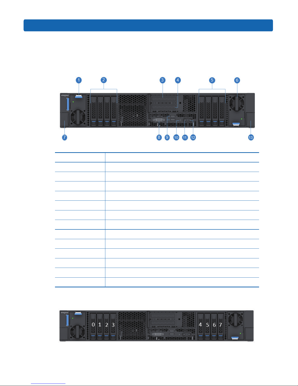
3.1 Front Panel Components
Item Descripon
1 PSU0
22.5” HDD module
3PCIE slot (CPU0/SW11)
4 PCIE slot (CPU1)
52.5” HDD module
6 PUS1
7 Quick release lever
8 Front VGA port
9 Front USB3.0 ports (2)
10 RST buon & fault LED
11 Power buon & LED
12 UID buon & LED
13 Quick release lever
● SAS/SATA HDD sequence diagram
10
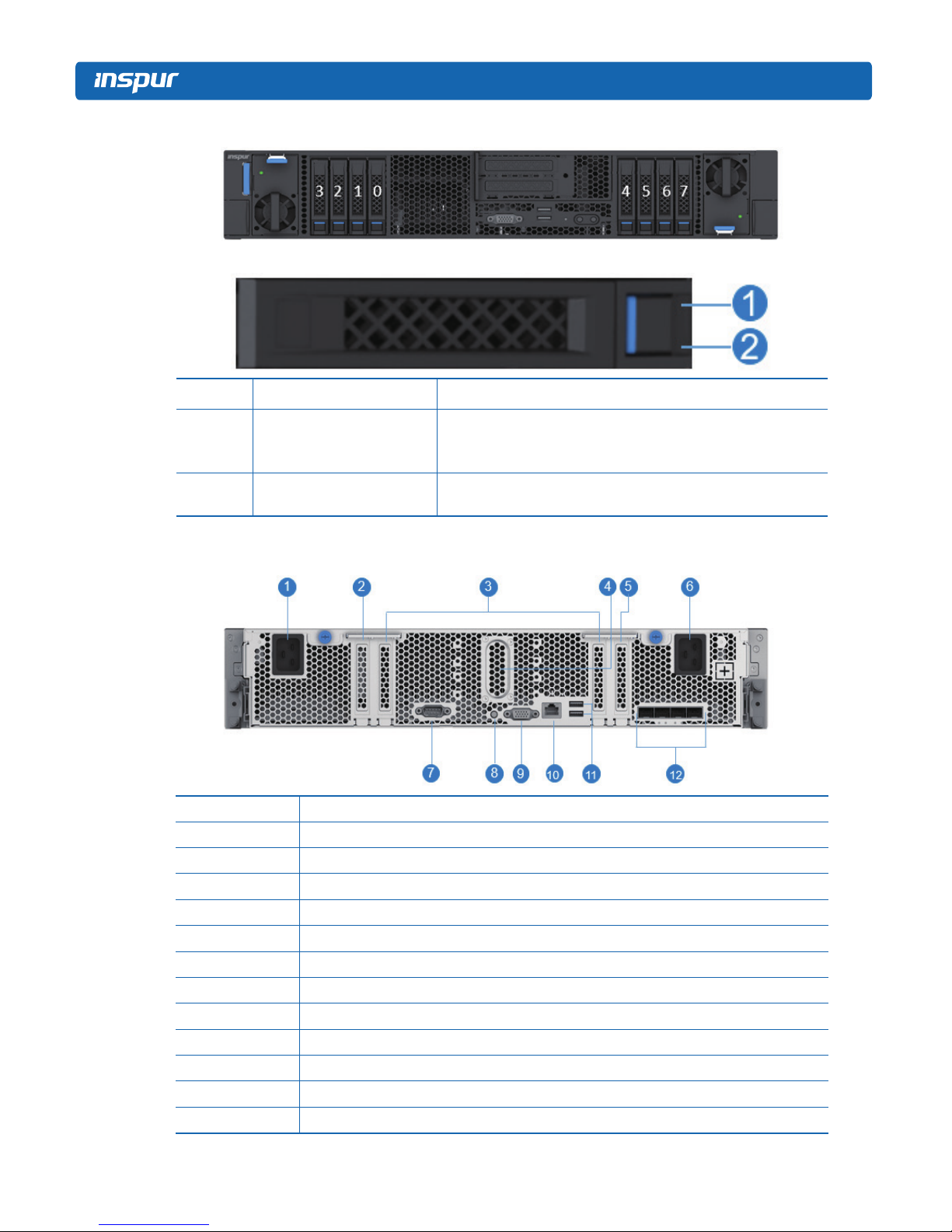
●NVME HDD sequence diagram
●HDD Bay LEDs
Item Descripon Status & Interpretaon
1 Fault alarm LED
Steady red: An HDD failure occurs
Steady blue: HDD posioning
Steady blue: RAID rebuilding
2Acvity status LED Steady green: Normal
Flashing green: Read and write acvity
3.2 Rear Panel Components
Item Descripon
1 Power input interface (1)
2 PCIE slot (SW1)
3 PCIE slots (SW0)
4Water-cooled input/output interface
5 PCIE slots (SW2)
6 Power input interface (2)
7 System interface
8UID buon & LED
9 VGA port
10 MLAN port
11 USB3.0 ports (2)
12 10G network ports (4)
11
Component Identication
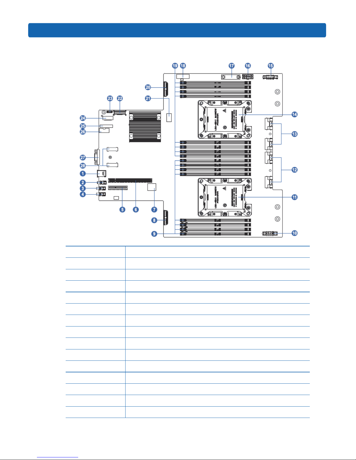
3.3 Motherboard Components
Item Descripon
1 USB3.0 ports (2)
2RST buon
3Power buon
4UID buon
5 M.2 Riser slot
6 PCIE Riser slot
7 BMC_TF slot
8SAS/SATA connector 0
9DIMM slots (CPU1)
10 PSU1 control connector
11 CPU1
12 PCIEx16_CPU0 SlimSAS connector 1
13 PCIEx16_CPU0 SlimSAS connector 2
14 CPU0

12
Item Descripon
15 PSU0 control connector
16 Fan board power connector
17 Fan board control connector
18 Rear IO Board connector 1
19 DIMM slots (CPU0)
20 SAS/SATA connector 1
21 CLR_CMOS
22 Rear IO Board connector 0
23 RAID KEY
24 XDP connector
25 TPM/TCM
26 CPLD programming interface
27 VGA port
28 RAID Card connectors
●Motherboard Jumper Introducon
See [3.3 Motherboard Components] for the jumper posion.
Item Descripon Funcon
CLR_CMOS CMOS clear jumper No jumper, normal status; short-circuit pins, clear CMOS.
Note:
1. CLR_CMOS only has two pins, without jumper equipped.
2. It is required to shut down the system, as well as disconnect the power supply during
CMOS clearing. Hold for 5 seconds aer short-circuing pins, and then remove the jumper
(default seng) to restore to its original status.

13
Operations
4 Operations
4.1 Power up the Server
Insert the power cord plug, then press the Power Buon.
4.2 Power down the Server
WARNING: To reduce the risk of personal injury, electric shock, or damage to the equipment,
remove the power cord to remove power from the server. The front panel Power Button
does not completely shut off system power. Portions of the power supply and some internal
circuitry remain active until AC power is removed.
IMPORTANT: If installing a hot-plug device, it is not necessary to power down the server.
1. Back up the server data.
2. Shut down the operang system.
3. Disconnect the power cords.
The system is now without power.
4.3 Extend the Server from the Rack
1. Open the handles outward and use a screwdriver to unlock the screws inside the left and
right ears.
2. Extend the server from the rack.
3. Rails are divided into two sections to slide out, that is:
3.1 When the fan needs online-maintenance, only pull out the first part of the rails, about
580mm (22.8 inches), and open the front access panel, to maintain the fan module or
motherboard on the rack.
3.2 When the whole machine needs maintenance, pull out the rails completely, about 100
centimeters (39.4 inches), you need to unlock the buckles on both sides of the rails
so that you can extend the chassis from the rack completely (Note: When the chassis
should be extended completely, make sure that the rear cables have all been removed).
WARNING: To reduce the risk of personal injury or equipment damage, be sure that the
rack is adequately stabilized before extending a component from the rack.

14
4. After performing the installation or maintenance procedure, slide the server back into the
rack until it clicks into place. Tighten the screws inside the two ears to secure the chassis
in place.
WARNING: To reduce the risk of personal injury, be careful when sliding the server into the
rack. The sliding rails could pinch your fingers.
4.4 Remove the Access Panel
WARNING: To reduce the risk of personal injury from hot surfaces, allow the drives and the
internal system components to cool before touching them.
Other manuals for NF5288M5
1
Table of contents


