InstaLighting NoLimit 4033 User manual
2
2
2 x 2
il 4033 LPV
2 x
2
il 4033 LPV
instalight NoLimit 4033
Anbauprofil klein/groß
Art.-Nr. il 4033 MK AB...
Montageanleitung DE
Sicherheitshinweise
Montage nur durch qualifiziertes Fachpersonal.
Schwere Verletzungen, Brand oder Sachschäden möglich. Anleitung vollständig lesen und beachten.
Anwendung nur im Innenbereich.
Lieferung ohne Montagemittel. Ausführung und Länge der benötigten Schrauben müssen vom Fachpersonal entsprechend der bauseits
vorhandenen Montagebedingungen gewählt werden.
Die Deckenkonstruktion muss so ausgeführt sein, dass diese das angegebene Metergewicht sowie sämtliche während der
Montage/Demontage zusätzlich auftretenden Druck- und Zugkräfte sicher aufnehmen kann.
Diese Anleitung ist Bestandteil des Produktes und muss beim Endkunden verbleiben.
Instalighting GmbH
Hohe Steinert 10
D-58509 Lüdenscheid
Telefon +49 (0) 2351 65619-0
Montage
02.12.2019
0000000133
(1a)
(2a)
(3)
(1b)
(2b)
a
b
ab
45
50
105
70
45
50
[mm]
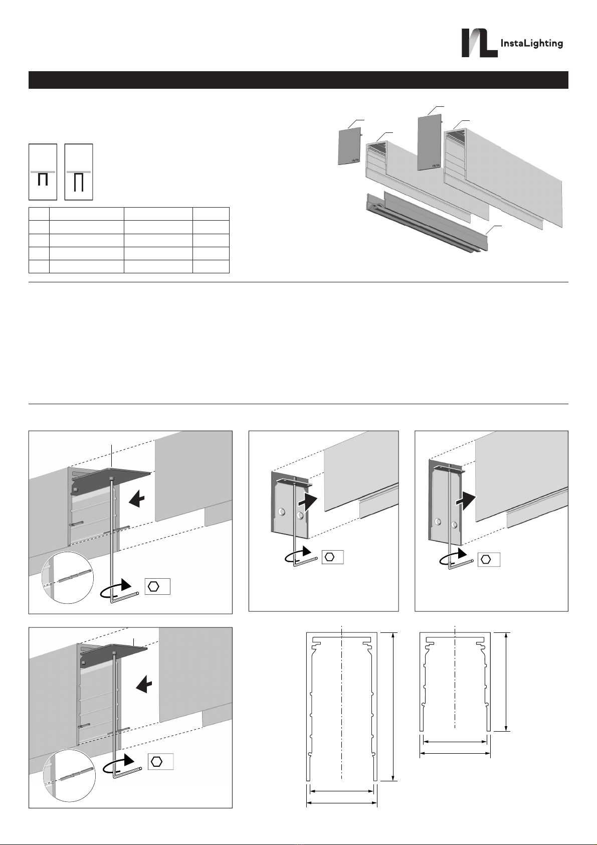
(1a) Anbauprofil klein il 4033 MK AB F ... L=2,3 m
(2a) Endkappe klein il 4033 AB SK F ... 2 Stck.
(1b) Anbauprofil groß il 4033 MK AB H ... L=2,3 m
(2b) Endkappe groß il 4033 AB SK H ... 2 Stck.
(3) Schutzabdeckung il 4033 ZM M 001 L=2,3 m
2x / 2.3 m
5
mm
?
Ø 18 mm
02.12.2019
0000000133
Anbauprofile verbinden (Bild 1 a+b)
▪Pendelprofile wie dargestellt mit Hilfe des Profilverbinder-Sets
(il 4033 LPV) aneinanderreihen.
▪Zur Fixierung Madenschrauben mit einem Innensechskant-Schlüssel
(SW 2) handfest anziehen.
Zum lichtdichten Abschluss, Stoßkanten an den Innenseiten mit
schwarzem Klebeband vom Typ tesaflex®4163 (nicht im Lieferumfang)
versiegeln.
Weiße Profilausführung: Schwarzes Klebeband zusätzlich mit weißem
Klebeband gleichen Typs überkleben.
Anbauprofile verschließen (Bild 2 a+b)
▪Stirnseiten der Anbauprofile mit Endkappe verschließen.
▪Zur Fixierung der Endkappen Madenschrauben mit einem
Innensechskant-Schlüssel (SW 2) handfest anziehen.
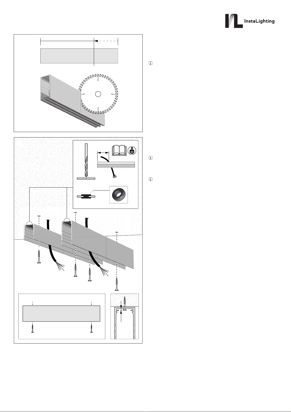
Anbauprofil kürzen (Bild 3)
Wenn notwendig, kann das Anbauprofil bauseits auf Maß gekürzt werden.
Dabei folgendes beachten:
▪Robuste Kappsäge mit Sägeblatt für Aluminium verwenden.
▪Zum Sägen Schutzabdeckung in das Profil einsetzen.
Kabeldurchführung herstellen (Bild 4)
▪Zur Einführung der Zuleitung eine Bohrung in der Bohrnut herstellen.
Die horizontale Position für die Kabeldurchführung hängt von der
späteren Bestückung des Einbauprofils ab und ist der Dokumentation
des Elektroplaners zu entnehmen.
▪Bohrung entgraten und Kabeltülle einsetzen.
Die Kabeltülle ist Bestandteil des Endkappen-Sets.
Anbauprofil montieren (Bild 4)
▪Mit Hilfe der Bohrnut im Anbauprofil Montagelöcher in einem Raster
passend zum Montagegrund vorbereiten. Dabei pro Profil (2,3 m)
mindestens eine Bohrung am Anfang und Ende vorsehen.
▪Zuleitung durch die Kabeltülle einfädeln und das Anbauprofil
anschließend mit Hilfe der Montagelöcher und geeigneten Schrauben
an der Decke befestigen.
Anhang
Technische Daten
Gewicht mit Lichtkomponenten
Anbauprofil klein 4,0 kg/m
Anbauprofil groß 5,2 kg/m
Max. Druckbelastung beim 100 N
Montieren von Lichkomponenten
Max. Zugbelastung beim 100 N
Demontieren von Lichkomponenten
Gewährleistung
Technische und formale Änderungen am Produkt, soweit sie dem
technischen Fortschritt dienen, behalten wir uns vor.
Wir leisten Gewähr im Rahmen der gesetzlichen Bestimmungen.
Bitte schicken Sie das Gerät portofrei mit einer Fehlerbeschreibung an
unsere zentrale Kundendienststelle:
Instalighting GmbH
Hohe Steinert 10
58509 Lüdenscheid
Deutschland
Al
Instalighting GmbH
Hohe Steinert 10
D-58509 Lüdenscheid
Telefon +49 (0) 2351 65619-0

2
2
2 x 2
il 4033 LPV
2 x
2
il 4033 LPV
instalight NoLimit 4033
Ceiling mounted profile small/large
Art. no. il 4033 MK AB...
Instruction manual EN
Safety instructions
Mounting only by qualified experts.
Serious injuries, fire or property damage possible. Please read and follow manual fully.
Only use indoors.
Delivery without mounting material. Type and length of the necessary screws must be selected by the experts in accordance with the moun-
ting conditions on-site.
The ceiling construction must be carried out in such a way that it can safely accommodate the given weight per metre as well as all additio-
nally occurring compressive and tensile forces during mounting / removal.
These instructions are an integral part of the product, and must remain with the end customer.
Instalighting GmbH
Hohe Steinert 10
D-58509 Lüdenscheid
Telephone +49 (0) 2351 65619-0
Mounting
02.12.2019
0000000133
(1a)
(2a)
(3)
(1b)
(2b)
a
b
ab
45
50
105
70
45
50
[mm]
(1a) Ceiling mounted profile small il 4033 MK AB F ... L=2.3 m
(2a) End cap small il 4033 AB SK F ... 2 Pcs.
(1b) Ceiling mounted profile large il 4033 MK AB H ... L=2.3 m
(2b) End cap large il 4033 AB SK H ... 2 Pcs.
(3) Protective cover il 4033 ZM M 001 L=2.3 m

2x / 2.3 m
5
mm
?
Ø 18 mm
02.12.2019
0000000133
Connecting ceiling mounted profiles (Figure 1 a+b)
▪String together the pendant profiles as depicted with the help of the
profile connector set (il 4033 LPV).
▪To fix them, tighten the grub screws with an Allen key (SW 2) by hand.
For a lightproof configuration, seal the internal edges with
black tesaflex®4163 tape (not included).
White profile design: in addition, tape over the black tape with white
tape of the same kind.
Sealing ceiling mounted profiles (Figure 2 a+b)
▪Seal the front sides of the ceiling mounted profiles with an end cap.
▪To fix the end caps, tighten the grub screws with an
Allen key (SW 2) by hand.
Shortening the ceiling mounted profile (Figure 3)
If necessary, the ceiling mounted profile can be shortened to measure
on site.
In doing so, the following should be observed:
▪Use a robust mitre saw with a saw blade for aluminium.
▪When sawing, place a protective cover in the profile.
Creating a cable gland (Figure 4)
▪To install the supply, make a borehole in the drilling slot.
The horizontal position for the cable gland depends on the
later placement of the installation profile and is to be taken from the
electrical engineer's documentation.
▪Deburr the hole and install the cable grommet.
The cable grommet is a component of the end cap set.
Mounting the ceiling mounted profile (Figure 4)
▪With the help of the drilling slot in the ceiling mounted profile, prepare
holes for mounting in a grid that is appropriate for the mounting surface.
For each profile (2.3 m), at least one hole is included at the beginning
and end.
▪Feed the supply line through the cable grommet and, following that,
attach the ceiling mounted profile to the ceiling with the help of
mounting holes and appropriate screws.
Appendix
Technical data
Weight with light components
Ceiling mounted profile small 4.0 kg / m
Ceiling mounted profile large 5.2 kg / m
Max. pressure load in 100 N
Mounting light components
Max. pressure load in 100 N
Removal of light components
Warranty
We reserve the right to make technical and formal changes to the product
in the interest of technical progress.
We provide a warranty as provided for by law.
Please send the unit postage-free with a description of the defect to our
central customer service office:
Instalighting GmbH
Hohe Steinert 10
58509 Lüdenscheid
Germany
Al
Instalighting GmbH
Hohe Steinert 10
D-58509 Lüdenscheid
Telephone +49 (0) 2351 65619-0
Table of contents
Languages:
Other InstaLighting Lighting Equipment manuals


Popular Lighting Equipment manuals by other brands


TIME LED
TIME LED Stellar 769591 Installation and operating instructions

Knightsbridge
Knightsbridge KIT4B Installation & maintenance manual

JONATHAN Y
JONATHAN Y JYL2080A instructions

Recom
Recom RACD06 Installation and operating instructions

Lightolier
Lightolier Lytespan 8672WH specification

ECCO SAFETY GROUP
ECCO SAFETY GROUP CODE 3 REFLEX C5517 Series Installation and operation instruction