InstaLighting 4010 DB User manual
(1)
(2)
(4)
(4)
(9)
(10)
(9)
(8)
(6)
(5)
(7) (2)
(11)
(12)
(3)
instalight 4010 DB
Lichtliniensystem, In-/Outdoor
Bedienungsanleitung
Sicherheitshinweise
Einbau und Montage elektrischer Geräte dürfen nur durch Elektrofachkräfte erfolgen.
Schwere Verletzungen, Brand oder Sachschäden möglich. Anleitung vollständig lesen und beachten.
Tragschienen, LED-Lampen und Acrylabdeckungen nicht durchbiegen. Dies führt zu Beschädigungen.
Die LED-Lampen dürfen nicht in Wasser getaucht werden. Es besteht die Gefahr eines elektrischen Schlages.
Für eine ausreichende Entwässerung sorgen.
Brandgefahr. An die Ausgangsleitung der LED-Lampen keine anderen Verbraucher außer LED-Lampen gleichen Typs anschließen.
Brandgefahr. LED-Lampe nicht an einen Dimmer anschließen.
LED-Lampe nicht an einen elektronischen Schalteinsatz anschließen. Fehlfunktion der Lampe.
Die Anschlussleitung ist nicht austauschbar. Bei beschädigter Anschlussleitung gesamten Leuchteinsatz austauschen.
Separate Bedienungsanleitungen „LEDLUX linear“ beachten.
Bei Nichtbeachtung der Anleitung können Schäden am Gerät, Brand oder andere Gefahren entstehen.
Diese Anleitung ist Bestandteil des Produktes und muss beim Endkunden verbleiben.
GEFAHR!
Elektrischer Schlag bei Berühren spannungsführender Teile.
Elektrischer Schlag kann zum Tod führen. Vor Anschluss des Lichteinsatzes Zuleitung freischalten!
Montage
Zum elektrischen Anschluss der LED-Lampen gesonderte Anleitung
„LEDLUX linear“ beachten.
Die minimale Einbaubreite für die Montage in Nuten beträgt 41 mm. Ist
die Einbaubreite kleiner, kann die Acrylabdeckung nicht montiert oder
demontiert werden.
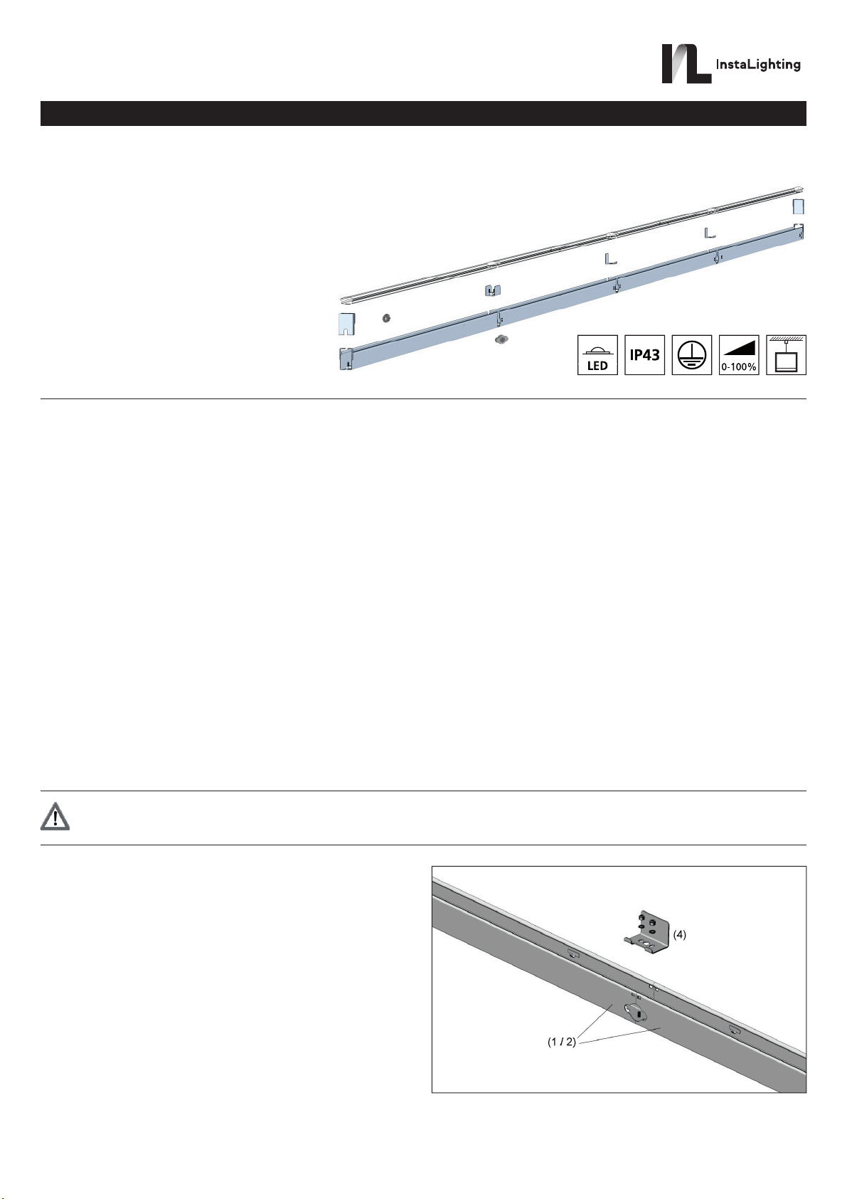
Tragschienen miteinander verbinden (Bild 2)
– Tragschienen (1 oder 2) auf einen ebenen Untergrund legen.
– Tragschienen-Verbinder (4) in die Tragschienen einsetzen.
– Tragschienen-Verbinder (4) mit beiliegenden Muttern festschrauben.
Um eine nicht benötigte seitliche Leitungseinführung zu verschließen, den
Tragschienen-Verbinder (4) spiegelverkehrt einsetzen.
05.12 .2019
82588931
Funktion
Bestimmungsgemäßer Gebrauch
– System zur Beleuchtung im Innen- und Außenbereich in Kombination mit LED-Leuchteinsätzen
– Edelstahl-Tragschienensystem mit Zubehörteilen zur Montage an Fassaden
Leuchtmittel / Wartung
Lichteinsatz mit Hochleistungs-LED-Leuchtmittel. Bei Defekt des Leuchtmittels muss der komplette Lichteinsatz ausgetauscht werden.
(1) Tragschiene, Anfangselement (für LED-Leuchtmittel 2286 mm)
(2) Tragschiene, Mittenelement (für LED-Leuchtmittel 2286 mm)
(3) Tragschiene, Endelement, bauseits kürzbar
(für LED-Leuchtmittel 226 – 2286 mm)
(4) Tragschienen-Verbinder
(5) Endelement-Verbinder
(6) Stirnkappe ohne Kabeleinführung
(7) Stirnkappe mit Kabeleinführung
(8) Acryloptik, Anfangselement, Abstrahlwinkel ±5°
(9) Acryloptik, Mittenelement, Abstrahlwinkel ±5°
(10) Acryloptik, Endelement, Abstrahlwinkel ±5°, bauseits kürzbar
(11) Gummitülle für Leitungseinführung-Tragschiene
(12) Gummitülle für Leitungseinführung-Stirnkappe
Bild 2
Instalighting GmbH
Hohe Steinert 10
D-58509 Lüdenscheid
Telefon +49 (0) 2351 65619-0

05.12.2019
82588931
Bild 4
Bild 5
Bild 6
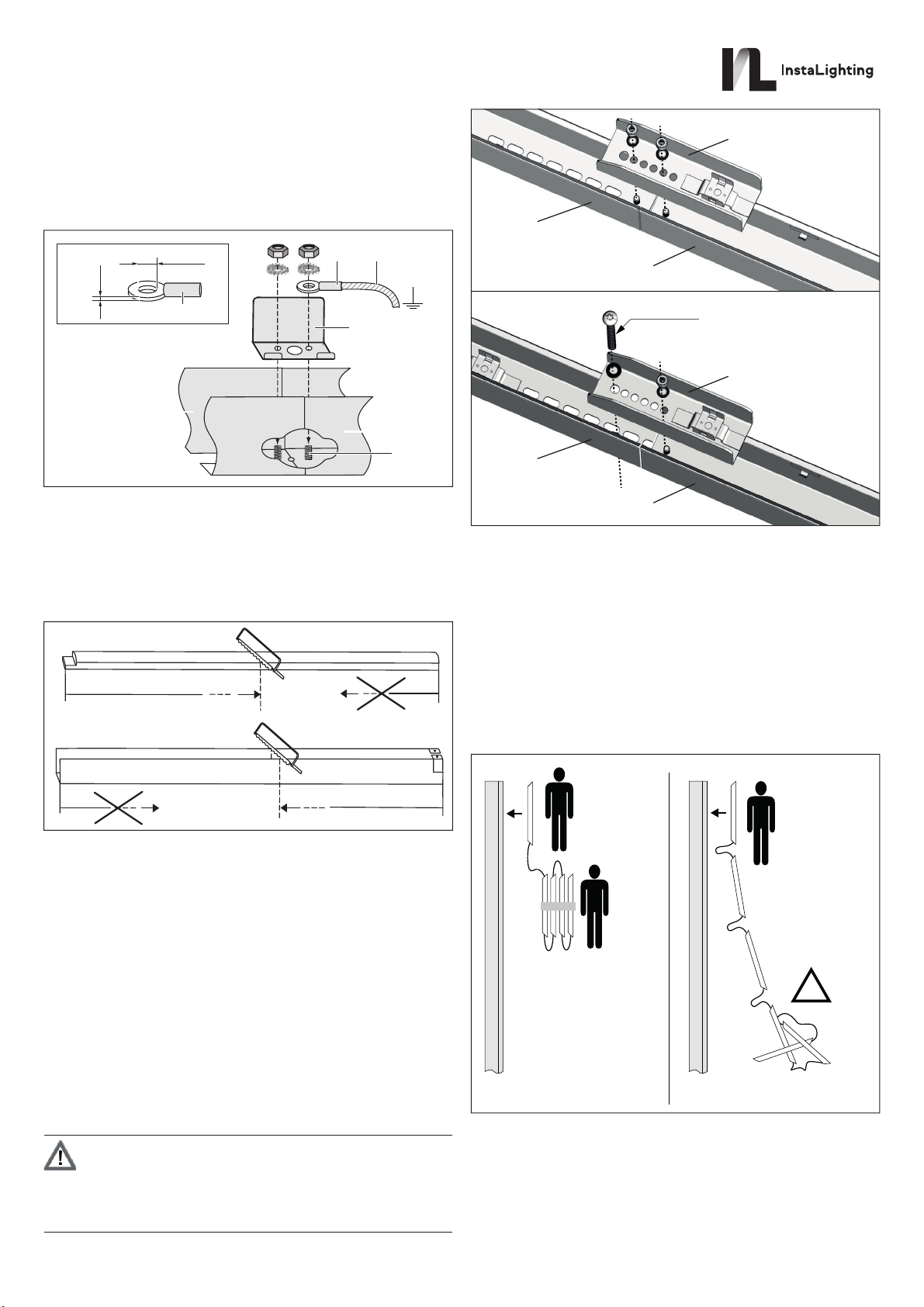
Potentialausgleich anschließen (Bild 3)
Zum Anschluss des Tragschienen-Systems an einen bauseits
vorhandenen Potentialausgleich (13) den M4-Gewindebolzen (14) sowie
einen Kabel-Ringschuh (15) gemäß Zeichnung verwenden (nicht im
Lieferumfang enthalten).
– Kabel-Ringschuh (15) zusammen mit dem Tragschienen-Verbinder (4)
am M4-Gewindebolzen (14) befestigen.
(7)
(1 / 2)
(1 / 2)
(13)(15)
d1,0
4,2 - 4,5
(15)
[mm]
(14)
Bild 3
Längenausgleich
Für eine optimale Längenanpassung wird das Tragschienen-Endelement
(3) verwendet. Die Mindestlänge des Endelementes (3) beträgt 150 mm.
Für dieses Element wird eine LED-Lampe mit der benötigten Länge als
Sondervariante gefertigt.
– Endelement (3) bei Bedarf wie dargestellt ablängen (Bild 4).
LED-Lampen montieren
Tragschienen sind montiert.
Separate Dokumentation der LED-Lampen beachten.
Umgang mit verketteten LED-Lampen (Bild 6)
Die LED-Lampen werden als Ketten mit mehreren verbundenen Elemente
geliefert. Um Beschädigungen an den LED-Lampen und den elektrischen
Anschlüssen zu vermeiden, folgende Hinweise beachten:
– Verkettete LED-Lampen mit mindestens zwei Personen installieren.
– Die verbundene Kette Lampe für Lampe auspacken, nicht alle
LED-Lampen auf einmal.
A
B
Ø 5 mm
(5)
(3)
(1 / 2)
(5)
(3)
(1 / 2)
min. 150 mm
min. 150 mm
– Tragschiene (1 / 2) und Endelement (3) auf einen ebenen
Untergrund legen.
– Endelement-Verbinder (5) in die Tragschienen (1 / 2) und das
Endelement (3) einlegen.
Bei ungekürztem Endelement (Bild 5 A):
– Endelement-Verbinder (5) mit den beiliegenden Muttern
mit Tragschiene (1 / 2) und Endelement (3) verschrauben.
Bei gekürztem Endelement (Bild 5 B):
– Endelement-Verbinder (5) mit beiliegender Mutter
mit Tragschiene (1 / 2) verschrauben.
– Endelement-Verbinder (5) und Endelement (3) werden erst bei
Montage am Montageort miteinander verschraubt. Die dafür benötigten
Schrauben sind nicht im Lieferumfang enthalten.
Tragschienen montieren
– Tragschienen mit geeigneten Schrauben befestigen.
VORSICHT!
Gefahr des Verbiegens des Tragschienen-Systems.
Bei Montage auf unebenem Untergrund können sich die
Tragschiene und das Endelement verbiegen.
In diesem Fall ist der sichere Halt der Acrylabdeckung nicht
mehr gegeben. Für einen ebenen Untergrund sorgen.
1
1
2
!
Falsch!Richtig!
Bei der Leitungsverlegung den minimalen Biegeradius der
Anschlussleitungen einhalten. Dieser ist in der Dokumentation der LED-
Lampen aufgeführt. Zur Einführung der Anschlussleitungen kann die
Leitungseinführung der Tragschiene oder die Leitungseinführung der
Stirnkappe verwendet werden.
– Anschlussleitung der LED-Lampen je nach gewälter
Leitungseinführung mithilfe der Gummitülle (10) oder (11) durch die
entsprechende Leitungseinführung nach außen führen.
Instalighting GmbH
Hohe Steinert 10
D-58509 Lüdenscheid
Telefon +49 (0) 2351 65619-0

Anhang
Technische Daten
Schlagfestigkeit (Edelstahlprofil / Optik) IK10 / IK08
Abmessungen (B x H) 40 x 60 mm
(Länge variabel)
Material Tragschiene: Edelstahl
Optik: Acryl
Gewicht 2,2 kg / m
Gewährleistung
Technische und formale Änderungen am Produkt, soweit sie dem
technischen Fortschritt dienen, behalten wir uns vor.
Wir leisten Gewähr im Rahmen der gesetzlichen Bestimmungen.
Bitte schicken Sie das Gerät portofrei mit einer Fehlerbeschreibung an
unsere zentrale Kundendienststelle:
Instalighting GmbH
Hohe Steinert 10
58509 Lüdenscheid
Deutschland
05.12.2019
82588931
Bild 10Bild 9
Bild 7
Bild 11
Bild 8
– Gummitülle in der dafür vorgesehenen Aussparung montieren.
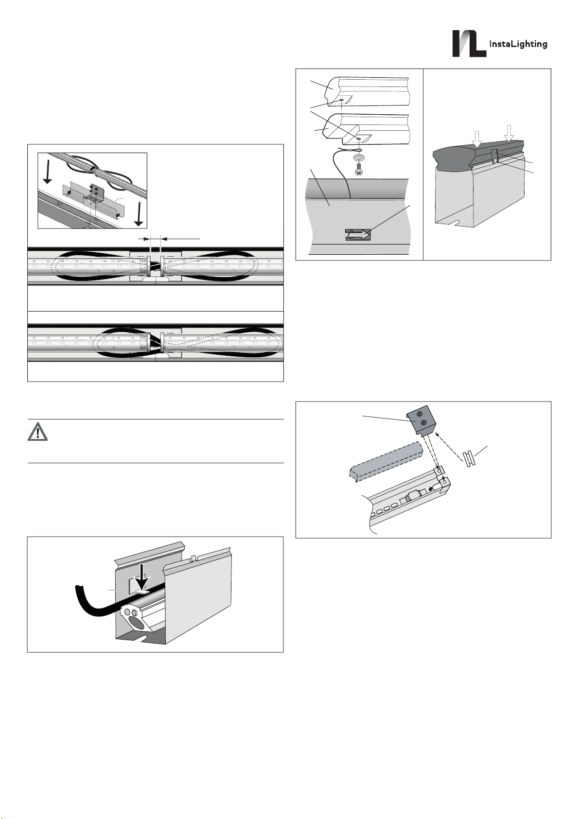
– LED-Lampen in die Halteklammern innerhalb der Tragschiene
drücken, bis diese einrasten. Dabei zwischen zwei LED-Lampen einen
Abstand von 10 mm einhalten (Bild 7). LED-Lampen sollten
nachträglich nicht mehr verschoben werden.
– Auf richtige Leitungsführung achten! Verbindungskabel müssen in
einer Schlaufe mittig unter beiden LED-Lampen verlegt werden (Bild 7).
Unter jeder Kabelschlaufe eine der mitgelieferten Isolierfolien (20)
platzieren!
FALSCH!
RICHTIG!
10 mm
Elektrischer Anschluss der LED-Lampen
GEFAHR!
Elektrischer Schlag bei Berühren spannungsführender Teile.
Elektrischer Schlag kann zum Tod führen. Elektrischen
Anschluss und Funktionsprüfung durch Elektrofachkraft
ausführen lassen.
Anschlussleitung fixieren
Alle Anschlussleitungen sind in der Tragschiene verlegt.
– Anschlussleitungen mit Kabelhalter (19) fixieren. Hierzu alle
Leitungsniederhalter (16) in der Tragschiene mit einem stumpfen
Gegenstand in waagerechte Position biegen (Bild 8).
Acryloptik montieren
Tragschienen und LED-Lampen sind montiert.
Acryloptik-Endelement bei Bedarf passend ablängen (Bild 4).
Sicherungsseile anbringen (Bild 9)
Alle einzelnen Acryoptik-Elemente müssen mit einem eigenen
Sicherungsseil gesichert werden. Dazu sind alle Elemente mit einem
Innengewinde (17) versehen.
– Ein Ende des Sicherungsseils am Acryloptik-Element (8 oder 9)
anschrauben.
– Das andere Ende des Sicherungsseils an der nächstliegenden
pfeilartigen Aussparung (18) der Tragschiene (1, 2 oder 3) einfädeln.
– Auf richtigen Sitz prüfen.
(16)
Acryloptiken einsetzen (Bild 10)
Alle Acryloptik-Elemente sind mit einem eigenen Sicherungsseil gesichert.
– Acryloptik-Elemente (8 oder 9) in Tragschiene so einrasten, dass die
Haltenase (19) in die Aussparung greift.
– Abgelängtes Acryloptik-Endelement in Tragschienen-Endelement (10)
einrasten.
Stirnkappe montieren (Bild 11)
Alle Acryloptiken sind eingerastet.
– Bei Stirnkappen mit Leitungseinführung (7) Gummitülle (12) für
Leitungseinführung einsetzten.
– Stirnkappen (6 oder 7) aufsetzen und festschrauben.
(17)
(10)
(8 / 9)
(1 / 2 / 3)
(18)
(8 / 9)
(19)
Klick !
(12)
(6 / 7)
(20)
Instalighting GmbH
Hohe Steinert 10
D-58509 Lüdenscheid
Telefon +49 (0) 2351 65619-0

(1)
(2)
(4)
(4)
(9)
(10)
(9)
(8)
(6)
(5)
(7) (2)
(11)
(12)
(3)
instalight 4010 DB
Light line system, in- / outdoor
Instruction manual
Safety instructions
Electrical equipment may only be installed and fitted by electrically skilled persons.
Serious injuries, fire or property damage possible. Please read and follow manual fully.
Avoid bending of the LED lamps, supporting rails and acrylic optics. This can cause damage.
The LED lamps should not be immersed in water. There is a risk of electric shock. Ensure adequate drainage.
Fire hazard. Do not connect any other consumers apart from the LED lamps of the same type to the output line.
Fire hazard. Do not operate the LED lamp on a dimmer.
Do not connect the LED lamp to an electronic switch insert. Malfunction of the lamp.
The connecting cable is not exchangeable. If the connecting cable is damaged, replace the LED lighting insert.
Please consult separate manuals "LEDLUX linear".
Failure to observe the instructions may cause damage to the device and result in fire and other hazards.
These instructions are an integral part of the product, and must remain with the end customer.
DANGER!
Electrical shock when live parts are touched.
Electrical shocks can be fatal. Before connecting the light insert, disconnect the supply line.
Fitting
When connecting the LED lamps consult the separate manual of the
"LEDLUX linear" lamps.
The minimum installation width for mounting in grooves is 41 mm. If the
installation width is smaller, the acrylic cover can not be mounted or
dismounted.
Interconnecting the mounting rails (figure 2)
– Place the mounting rails (1 or 2) on a planar ground.
– Insert the mounting rail fittings (4) into the mounting rails.
– Fasten the mounting rail fittings (4) using the nuts supplied.
To close any unused sidewise cable inlets, place the mounting rail fitting
(4) in mirror-inverted direction.
05.12.2019
82588931
Function
Intended use
– System for illumination of indoor and outdoor areas in combination with LED light inserts
– Stainless steel supporting rail system with accessory parts for installation on facades
Lamps / Maintenance
Lighting insert with high-performance LED lamps. In case of lamp damage the complete light insert must be replaced.
(1) Mounting rail, front element (for LED lamp 2286 mm)
(2) Mounting rail, middle element (for LED lamp 2286 mm)
(3) Mounting rail, end element, to be cut to length on site
(for LED lamp 226 – 2286 mm)
(4) Mounting rail fitting
(5) End element fitting
(6) Front cap without cable inlet
(7) Front cap with cable inlet
(8) Acrylic optics, front element, radiation angle ±5°
(9) Acrylic optics, middle element, radiation angle ±5°
(10) Acrylic optics, end element, radiation angle ±5°,
to be cut to length on site
(11) Rubber grommet for mounting rail with cable entry
(12) Rubber grommet for front cap with cable entry
Figure 2
Instalighting GmbH
Hohe Steinert 10
D-58509 Lüdenscheid
Telephone +49 (0) 2351 65619-0
05.12.2019
82588931
Figure 4
Figure 5
Figure 6
Connecting the potential equalization (figure 3)
For connection of the mounting rail system to an existing potential
equalization (13), use the M4 threaded bolt (14) in combination with a ring
cable lug (15) according to drawing (not in scope of delivery).
– Fasten the ring cable lug (15) together with the mounting rail fitting (4)
to the M4 threaded bolt (14).
Length adjustment
(7)
(1 / 2)
(1 / 2)
(13)(15)
d1,0
4,2 - 4,5
(15)
[mm]
(14)
Figure 3
Use mounting rail end element (3) for optimal length adjustment. Minimum
length of the end element (3) is 150 mm. For this element an LED lamp
with needed length has to be manufactured as a special variant.
– Trim the end element (3) as needed according to the drawing (figure 4).
– Place the mounting rail (1 / 2) and end element (3) to a planar
ground.
Mounting the LED lamps
Mounting rails are installed.
Consider separate documentation of the LED lamps.
Handling of chained LED lamps (figure 6)
The LED lamps are delivered as chains consisting several interconnected
elements. To avoid damage on the LED lamps and electrical connections
observe the following instructions:
– Installing chained LED lamps shall be done by at least two workers.
– Unpack the connected chain lamp by lamp, not all
LED lamps at once.
A
B
Ø 5 mm
(5)
(3)
(1 / 2)
(5)
(3)
(1 / 2)
min. 150 mm
min. 150 mm
– Insert the end element fittings (5) into mounting rails (1 / 2) and
end element (3).
With unshortened end element (figure 5 A):
– Screw end element fittings (5), mounting rail (1 /2) and
end element (3) together by using the supplied nuts.
With shortened end element (figure 5 B):
– Screw end element fittings (5) and mounting rail (1 / 2) together
by using the supplied nuts.
– End element fitting (5) und end element (3) will not be screwed together
until installing the mounting rail on site. The screws required for this
are not included in the scope of delivery.
Mounting the supporting rails
– Fasten the mounting rails using suitable screws.
CAUTION!
Risk of bending of the mounting rail system.
If installed on uneven ground, mounting rail and end
element can be deformed.
In this case a safe hold of the acrylic cover is no langer
guaranteed. Take care of a planar mounting ground.
1
1
2
!
INCORRECT!CORRECT!
When routing the lines, observe the minimum bending radius of the
connecting cables. This is listed in the documentation of the LED lamps.
For insertion of the connection cable the cable inlet of the mounting rail or
front cap can be used.
– Dependent on the chosen cable inlet use rubber grommet (10) or (11)
when routing the connection cable out of the mounting rail.
Instalighting GmbH
Hohe Steinert 10
D-58509 Lüdenscheid
Telephone +49 (0) 2351 65619-0
Appendix
Technical data
Impact strength (stainless steel profile / optics) IK10 / IK08
Dimensions (W × H) 40 x 60 mm
(Variable length)
Material Mounting rail:
stainless steel
Optics: Acrylic
Weight 2.2 kg / m
Warranty
We reserve the right to make technical and formal changes to the product
in the interest of technical progress.
We provide a warranty as provided for by law.
Please send the unit postage-free with a description of the defect to our
central customer service office:
Instalighting GmbH
Hohe Steinert 10
58509 Lüdenscheid
Germany
05.12.2019
82588931
Figure 10Figure 9
Figure 7
Figure 11
Figure 8
– Place the rubber grommet into the opening for cable entry.
– Press LED lamps into the retaining clips inside of the supporting rail,
until they lock. In doing so observe a distance of 10 mm between two
LED lamps (figure 7). LED lamps should not be subsequently shifted.
– Make sure that the cable routing is correct! Link cables must be routed
in a loop below the middle of both LED lamps (figure 7). Place one of
the delivered insulation foils (20) below each cable loop!
INCORRECT!
CORRECT!
10 mm
Elektrical connection of the LED lamps
DANGER!
Electrical shock when live parts are touched. Electrical
shocks can be fatal. Electrical connection and functional
check must be done by an electrically skilled person.
Locking the connection cable into position
All connection cables are routed inside of the mounting rail.
– Fix the connection cables using cable holders (16). For this
bend all cable holders (16) inside of the mounting rails into horizontal
position by using a blunt instrument (figure 8).
Mounting the acrylic optics
Mounting rails and LED lamps are installed.
Trim the acrylic optics end element as needed (figure 4).
Installing the safety wires (figure 9)
All separate acrylic optics shall be saved with their own safety wire. For
this all elements are equipped with an internal thread (17).
– Screw one end of the safety wire to the acrylic element (8 or 9).
– Clip the other end of the safety wire to the nearest
arrow-like hook (18) of the mounting rail (1, 2 or 3).
– Check the correct placement.
(16)
Inserting the acrylic optics (figure 10)
All acrylic elements are saved with their own safety wire.
– Lock acrylic elements (8 or 9) into the mounting rails in a way
that the retaining lug (19) locks into the gap.
– Lock shortened acrylic end element into mounting rail
end element (10).
Mounting the front cap (figure 11)
All acrylic optics are locked.
– For front caps with cable inlet (7) apply rubber grommet (12) for
cable insertion.
– Place and screw the front caps (6 or 7).
(17)
(10)
(8 / 9)
(1 / 2 / 3)
(18)
(8 / 9)
(19)
Klick !
(12)
(6 / 7)
(20)
Instalighting GmbH
Hohe Steinert 10
D-58509 Lüdenscheid
Telephone +49 (0) 2351 65619-0
Table of contents
Languages:
Other InstaLighting Lighting Equipment manuals


