InstaLighting instalight NoLimit 4033 User manual

?
Ø 18 mm
2
2 x
2
il 4033 LPV
instalight NoLimit 4033
Deckeneinbauprofil mit Rahmen
Art.-Nr. il 4033 MK EB...
Montageanleitung DE
Sicherheitshinweise
Montage nur durch qualifiziertes Fachpersonal.
Schwere Verletzungen, Brand oder Sachschäden möglich. Anleitung vollständig lesen und beachten.
Anwendung nur im Innenbereich.
Lieferung ohne Montagemittel. Ausführung und Länge der benötigten Schrauben müssen vom Fachpersonal entsprechend der bauseits
vorhandenen Montagebedingungen gewählt werden.
Die Deckenkonstruktion muss so ausgeführt sein, dass diese das angegebene Metergewicht sowie sämtliche während der
Montage/Demontage zusätzlich auftretenden Druck- und Zugkräfte sicher aufnehmen kann.
Diese Anleitung ist Bestandteil des Produktes und muss beim Endkunden verbleiben.
Montage
02.12.2019
0000000182
(1)
(3)
(2)
(4)
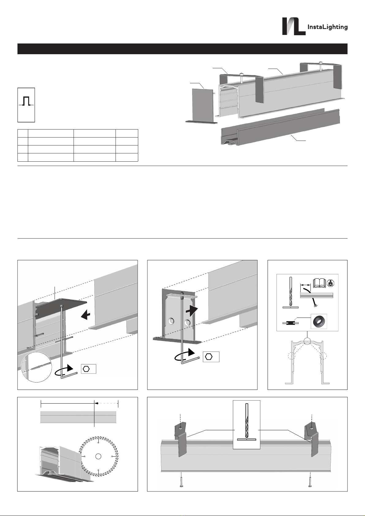
(1) Einbauprofil il 4033 MK EB ... L=2,3 m
(2) Montagebügel il 4033 EB R SB 2 Stck.
(3) Endkappe il 4033 EB SK R ... 2 Stck.
(4) Schutzabdeckung il 4033 ZM M 001 L=2,3 m
Al Ø 4.5 mm
5x / 2.3 m
Instalighting GmbH
Hohe Steinert 10
D-58509 Lüdenscheid
Telefon +49 (0) 2351 65619-0

55 +2/-0 30
90
20
1. 2.
02.12.2019
0000000182
Einbauprofile verbinden (Bild 1)
▪Einbauprofile wie dargestellt mit Hilfe des Profilverbinder-Sets
(il 4033 LPV) aneinanderreihen.
▪Zur Fixierung Madenschrauben mit einem Innensechskant-Schlüssel
(SW 2) handfest anziehen.
Einbauprofile verschließen (Bild 2)
▪Stirnseiten der Einbauprofile mit Endkappe verschließen.
▪Zur Fixierung der Endkappen Madenschrauben mit einem
Innensechskant-Schlüssel (SW 2) handfest anziehen.
Kabeldurchführung herstellen (Bild 3)
▪Zur Einführung der Zuleitung eine Bohrung in der oberen oder
seitlichen Bohrnut herstellen.
Die horizontale Position für die Kabeldurchführung hängt von der
späteren Bestückung des Einbauprofils ab und ist der Dokumentation
des Elektroplaners zu entnehmen.
▪Bohrung entgraten und Kabeltülle einsetzen.
Die Kabeltülle ist Bestandteil des Endkappen-Sets.
▪Zuleitung durch die Kabeltülle in das Profil führen.
Einbauprofil kürzen (Bild 4)
Wenn notwendig, kann das Einbauprofil bauseits auf Maß gekürzt werden.
Dabei folgendes beachten:
▪Robuste Kappsäge mit Sägeblatt für Aluminium verwenden.
▪Zum Sägen Schutzabdeckung in das Profil einsetzen.
Schwenkbügel montieren (Bild 5)
▪Abstand der Schwenkbügel abhängig von der Tragfähigkeit der Decke
wählen. Empfohlen: Fünf Schwenkbügel pro Profil (L=2,3 m).
▪Pro Schwenkbügel eine Bohrung in der oberen Bohrnut des
Einbauprofils herstellen.
▪Schwenkbügel wie dargestellt montieren.
Einbauprofil montieren (Bild 6)
▪Deckenausschnitt mit einer Breite von 55 mm (+2/-0 mm) herstellen.
Die Länge des Deckenausschnitts entspricht der Gesamtlänge des
Einbauprofilsprofils zuzüglich 2 mm je Endkappe.
▪Montagebügel mit einem Schraubendreher TX20 vollständig lösen.
▪Einbauprofil von unten in den Deckenausschnitt einsetzen, bis der
Rahmen bündig an der Decke anliegt.
▪Montagebügel mit einem Schraubendreher TX20 soweit anziehen, bis
das Einbauprofil mit dem Rahmen stramm an der Decke anliegt.
Je nach Beschaffenheit des Deckenmaterials kann es notwendig sein,
die Auflageflächen der Haltebügel mit einer Leiste aus Holz oder Metall
zu verstärken.
Anhang
Technische Daten
Gewicht mit Lichtkomponenten 4,0 kg/m
Max. Druckbelastung beim 100 N
Montieren von Lichkomponenten
Max. Zugbelastung beim 100 N
Demontieren von Lichkomponenten
Gewährleistung
Technische und formale Änderungen am Produkt, soweit sie dem
technischen Fortschritt dienen, behalten wir uns vor.
Wir leisten Gewähr im Rahmen der gesetzlichen Bestimmungen.
Bitte schicken Sie das Gerät portofrei mit einer Fehlerbeschreibung an
unsere zentrale Kundendienststelle:
Instalighting GmbH
Hohe Steinert 10
58509 Lüdenscheid
Deutschland
Instalighting GmbH
Hohe Steinert 10
D-58509 Lüdenscheid
Telefon +49 (0) 2351 65619-0
?
Ø 18 mm
2
2 x
2
il 4033 LPV
instalight NoLimit 4033
Recessed profile with frame
Art. no. il 4033 MK EB...
Instruction manual EN
Safety instructions
Mounting only by qualified experts.
Serious injuries, fire or property damage possible. Please read and follow manual fully.
Only use indoors.
Delivery without mounting material. Type and length of the necessary screws must be selected by the experts in accordance with the moun-
ting conditions on-site.
The ceiling construction must be carried out in such a way that it can safely accommodate the given weight per metre as well as all additio-
nally occurring compressive and tensile forces during mounting / removal.
These instructions are an integral part of the product, and must remain with the end customer.
Mounting
02.12.2019
0000000182
(1)
(3)
(2)
(4)
(1) Installation profile il 4033 MK EB ... L=2.3 m
(2) Mounting bracket il 4033 EB R SB 2 Pcs.
(3) End cap il 4033 EB SK R ... 2 Pcs.
(4) Protective cover il 4033 ZM M 001 L=2.3 m
Al Ø 4.5 mm
5x / 2.3 m
Instalighting GmbH
Hohe Steinert 10
D-58509 Lüdenscheid
Telephone +49 (0) 2351 65619-0

55 +2/-0 30
90
20
1. 2.
02.12.2019
0000000182
Connecting the installation profiles (Figure 1)
▪String together the installation profiles as depicted with the help of the
profile connector set (il 4033 LPV).
▪To fix them, tighten the grub screws with an Allen key (SW 2) by hand.
Sealing the installation profiles (Figure 2)
▪Seal the front sides of the installation profiles with an end cap.
▪To fix the end caps, tighten the grub screws with an
Allen key (SW 2) by hand.
Creating a cable gland (Figure 3)
▪To install the supply, make a borehole in the upper drilling slot
or the drilling slot on the side.
The horizontal position for the cable gland depends on the
later placement of the installation profile and is to be taken from the
electrical engineer's documentation.
▪Deburr the hole and install the cable grommet.
The cable grommet is a component of the end cap set.
▪Guide the supply line through the cable grommet to the profile.
Shortening the installation profile (Figure 4)
If necessary, the installation profile can be shortened to measure on site.
In doing so, the following should be observed:
▪Use a robust mitre saw with a saw blade for aluminium.
▪When sawing, place a protective cover in the profile.
Mounting the pivoting bracket (Figure 5)
▪The distance of the pivoting bracket is to be chosen dependent on the
ceiling's load-bearing capacity. Recommended: five pivoting brackets
for each profile (L=2.3 m).
▪For each pivoting bracket, a borehole should be made in the installation
profile's upper drilling slot.
▪Mount the pivoting bracket as illustrated.
Mounting the installation profile (Figure 6)
▪Make a ceiling cutout with a width of 55 mm (+2/-0 mm).
The length of the ceiling cutouts corresponds to the total length of the
installation profile, plus 2 mm per end cap.
▪Completely release the mounting brackets with a TX20 screwdriver.
▪Place the installation profile into the ceiling cutout from below, until the
frame is flush with the ceiling.
▪Tighten the mounting brackets with a TX20 screw driver until the
installation profile with its frame is tight against the ceiling.
Depending on the quality of the ceiling material, it may be necessary
to reinforce the supporting surface of the supporting brackets with
moulding made out of wood or metal.
Appendix
Technical data
Weight with light components 4.0 kg / m
Max. pressure load in 100 N
Mounting light components
Max. pressure load in 100 N
Removal of light components
Warranty
We reserve the right to make technical and formal changes to the product
in the interest of technical progress.
We provide a warranty as provided for by law.
Please send the unit postage-free with a description of the defect to our
central customer service office:
Instalighting GmbH
Hohe Steinert 10
58509 Lüdenscheid
Germany
Instalighting GmbH
Hohe Steinert 10
D-58509 Lüdenscheid
Telephone +49 (0) 2351 65619-0
Table of contents
Languages:
Other InstaLighting Lighting Equipment manuals


Popular Lighting Equipment manuals by other brands


Good Earth Lighting
Good Earth Lighting SE1092-BP2-00LF0-G quick start guide

Lights.com
Lights.com LC003802 installation instructions

CREE LIGHTING
CREE LIGHTING XSP Series Disassembly instructions

MELINERA
MELINERA 60306 Operation and safety notes

BEMKO
BEMKO ST41-104-PIR Security instructions

CristalRecord
CristalRecord LAXITY quick start guide

Good Earth Lighting
Good Earth Lighting G9712L-T5-WHESI quick start guide

Nora
Nora NSPEC NUTP8-LED installation instructions

Saxby Lighting
Saxby Lighting 46393 Instruction leaflet

Nitecore
Nitecore tm 15 user manual

ACME
ACME IM-250 SP user guide

Larson Electronics
Larson Electronics EPLC2-LED-50W-RT-JB5 instruction manual