Instantel Minimate Pro User manual

The World’s Most Trusted Monitors — Vibration · Noise · Air Overpressure
www.instantel.com
www.instantel.com
Instruction Sheet
1Page
The Sound Level Microphone for the Minimate Pro4/Pro6
monitoring unit, automates sound/noise monitoring
for a range of applications including: building activities,
construction, trafc, mining operations and quarries. The
Minimate Pro combines noise and vibration monitoring in
the same unit making it a cost effective and flexible system.
It meets the requirements for IEC 61672 Class 1, including
A and C weighted specications and has a measuring range
from 30 to 140 dB with a Fast or Slow response. It is also
capable of recording the unltered response in one of two
ranges, +/- 25 Pa or +/- 100 Pa (requires THOR Advanced).
The record mode can be set to Manual trigger, Waveform
(records up to 9,000 seconds once it has been triggered)
Histogram (2-second to 1-hour intervals) or simultaneously recording
both Histogram and Waveform in Histogram-Combo mode.
In THOR’s Advanced software setup, the Sound Level Microphone can also trigger and record unltered
sound clips (1-125 seconds at 65,536 S/s or 1-32,400 seconds at 512 S/s). The resulting data le can
then be played back in THOR to help determine the source, or it can be processed further, including third
octave frequency analysis.
The Minimate Pro can monitor up to four (Pro4) or six (Pro6) Sound Level Microphones simultaneously in
Advanced mode with the use of one or two Splitter Boxes (P/N: 720A5501).
Sound Level Microphone
Tools and Materials Required
• Minmate Pro4 monitoring unit . . . . . . . . . . . (P/N: 720A2301) or
• Minmate Pro6 monitoring unit . . . . . . . . . . . (P/N: 720A2401)
• Sound Level Microphone . . . . . . . . . . . . . . . . (P/N: 720A5101) Stand and windscreen included.
• Minimate Pro Splitter Box . . . . . . . . . . . . . . . (P/N: 720A5501)
• Extension cables, as required
30 m (100 ft) . . . . . . . . . . . . . . . . . . . . . . (P/N: 720A3301)
75 m (250 ft) . . . . . . . . . . . . . . . . . . . . . (P/N: 720A3302)
Custom Length Extension Cable . . . . (P/N: 301-000034-000)
Custom Cable Connector Assembly . .(P/N: 720A3305)
• THOR Advanced software . . . . . . . . . . . . . . (P/N: 72300201)
• Optional Field Calibration devices:
Delta OHM HD9101 Class 1
Brüel & Kjaer Sound Calibrator Type 4231
Rion NC-74 Sound Calibrator
Range of Applications
• Construction
• Mining
• Building Activities
• Trafc
• Quarries
2Page
1
2
3
4
65
8
7
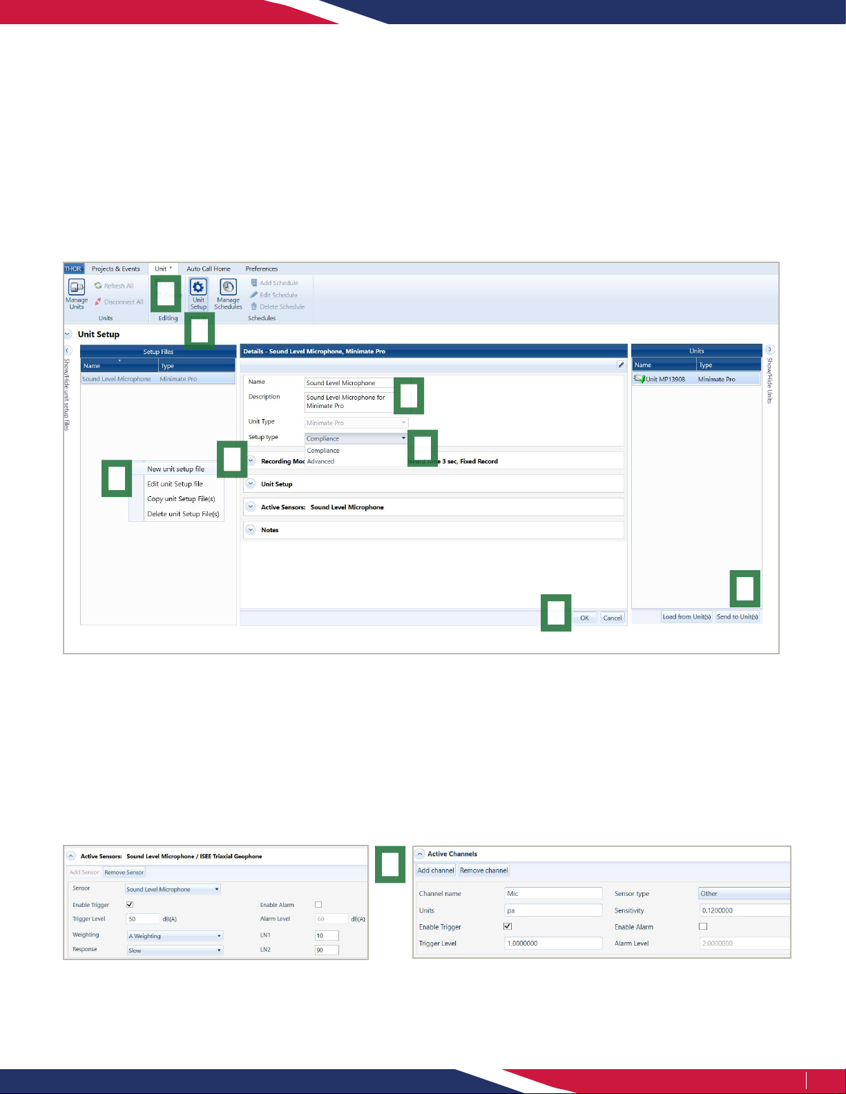
THOR Software Setup
The Sound Level Microphone can be congured using THOR software and then sent to the unit.
1. Within THOR, click on the Unit Tab.
2. Click on the Unit Setup icon.
3. In the Unit Setup section, right-click and select New Unit Setup File.
4. Fill in the details and select Unit Type: Minimate Pro
5. Select the Setup Type, Compliance or Advanced.
6. Select the Record Mode and ll in the recording details.
Advanced Mode
i. Under Active Channels, click on Add Channel.
ii. Under Sensor Type select Other and enter the Sensitivity
according to the Microphone (0.12 or 0.0038).
iii. Enter the units (Pa) and other parameters as required.
iv. Repeat steps i. through iii. to add more Sound Level
Microphones (Splitter Box required).
7. Depending on which Setup Type you choose you will have different options:
Compliance Mode
i. Under Active Sensors, click on Add Sensor.
ii. Under Sensor select Sound Level Microphone.
iii. Fill in any Trigger details for Trigger level, Weighting,
Response, LN1 and LN2.
(In this section you can also configure the external alarm.)
8. Click on OK to save the Setup File.
9. Select the Minimate Pro unit and click Send to Unit(s) to send the conguration le to the Minimate Pro monitoring unit.
9

3Page
Minimate Pro Setup
Once the Setup le is sent to the Minimate Pro unit, all parameters are ready for monitoring. If you wish to modify these
parameters from the unit itself then:
1. On the Minimate Pro press the Setup key.
2. Use the down arrow key to reach View/Edit Setup File and press the Enter (Checkmark) key.
3. Use the down arrow key to reach Sample Rate then scroll through the available options with the right arrow key.
4. Use the down arrow key to reach Sound Mic Setup then enter the menu using the right arrow.
5. Use the right arrow key to choose between A weighting and C weighting then Mic Response Slow / Fast then press
the Enter (Checkmark) key.
6. Use the down arrow key to reach Trigger Level, then enter the menu using the right arrow.
7. Use the down arrow key to reach Pressure Trigger and toggle between On/Off using the right arrow key.
8. Use the down arrow key to reach Pressure Trigger Level and enter the menu using the right arrow.
9. Use the arrow keys to set the trigger level and press the Enter (Checkmark) key to register the value.
10. Press the Enter (Checkmark) key 4x to save the values to the Setup le.
Specications
Field Compliance Mode
THOR Advanced Mode (Optional)
Normal Sensitive
Weighting A-Weight or C-Weight Unltered Unltered
Frequency Range 10 Hz to 20 kHz 10 Hz to 20 kHz
Response Fast (125 ms) or Slow (1 s) N/A
Sensitivity N/A 0.0038 V/Pa 0.12 V/Pa
Resolution 0.05 dB (display limit 0.1dB) 0.03 Pa 0.89 mPa
Range Automatic +/- 100 Pa +/- 25 Pa
Trigger Levels 33 dB to 140 dB 0.448 to 100 Pa 0.01424 to 25 Pa
Sample Rate Up to 4,096 S/s
(1,024 S/s recommended) up to 65,536 S/s (recommended)
Temperature Range -10° to 50°C (14° to 122°F) -10° to 50°C (14° to 122°F)
Cable Length 2 m (6.5 ft) 2 m (6.5 ft)
Maximum Amplitude 160 dB 160 dB
Physical Installation
1. If required, assemble the stand.
2. Point the microphone in the direction of the sound or noise source.
3. Connect the microphone to the Minimate Pro as shown in page 4.
4. Push the Sensor Check button on the keypad to ensure proper functioning of the microphone (Only available
when in Compliance mode).
5. If required, place the windscreen on the end of the microphone.

4Page
Field Calibration
The Minimate Pro provides an option to calibrate the Sound Level Microphone in the eld. When calibrating in the eld,
the calibration date is set to the current date, and the name of the calibrator is set to “Field Calibration” this will also
appear on event reports.
Note: Only use an Instantel recommended calibrating device (see the Tools and Materials Required section).
1. Attach the Sound Level Microphone to the Pressure channel of the Minimate Pro4 (Channel 4) or Minimate Pro6 (Channels 4-6).
2. Select the Setup key.
3. Press the Down Arrow key to scroll and highlight the Maintenance menu.
4. Press the Enter key.
5. Press the Down Arrow key to scroll and highlight Sound Level Microphone Field Calibration.
6. Press the Right Arrow key to accept the selection.
7. The Calibrate Sound Level Microphone menu appears. This menu displays the following message:
“The calibration date will be set to:” and shows the current date.
8. Press the Right Arrow key to select the Calibrate command, or press the Cancel key to return to the Maintenance menu.
9. If the Calibrate command was selected, a new prompt appears:
“Connect Sound Level Microphone to Channel 4 – Connect and turn on calibration reference.”
10. Follow the instructions in the operator manual of the eld calibration device to attach it to the end of the microphone and set
the reference to 94 dBA. (Remove the windscreen from the Sound Level Microphone before attaching the calibration device.)
11. Press the Right Arrow key to select the Calibrate command, or press the Cancel key to return to the Maintenance menu.
12. When complete, the Minimate Pro will display one of four messages:
a) If the measured signal is less than 94 dB:
“Error Calibrating Sound Level Microphone. Calibration reference not detected. Existing Calibration retained.”
b) If the measured signal is greater than 94 dB:
“Error Calibrating Sound Level Microphone.Calibration reference signal too large. Existing Calibration retained.”
c) If the monitor and eld calibration instrument are unable to calibrate the microphone:
“Unable to calibrate the Sound Level Microphone. Please send Microphone to be serviced.”
d) If the eld calibration was successful:
“Sound Level Microphone Calibration successful. Do you wish to use calibration?”
13. Do one of the following:
• To save the calibration results, press the Right Arrow.
• To retain the original calibration date, press Cancel.
If the changes are accepted, the information will appear on the Event Report showing the Company Name of the Calibrator
in the Field Calibration eld. Refer to the THOR software operator manual for more information.

980-720005-000 Rev 08 - Product Specications are Subject to Change
5Page
Toll Free (N.A.): 1.800.267.9111
Telephone: 1.613.592.4642
Email: [email protected]
www.instantel.com
Warranty
Instantel products come with a one-year warranty. Monitoring units and sensors will have the warranty extended for a second year
if they are returned to the Instantel factory for service and calibration within 30 days of the ‘Next Calibration’ date printed on the
calibration label located on the product.
If within a period of one year from the date of shipment to a customer, the instrument fails to perform in accordance with
Instantel’s published specications and the operator’s manual, due to a defect in materials or workmanship, it will be repaired
or replaced at Instantel’s option, free of charge. This warranty is void if the equipment has been dismantled, altered or abused
in any way. This warranty is nontransferable.
This warranty does not include any implied warranty of functionality for a particular purpose. Instantel assumes no
responsibility for damages of any description resulting from the operation or use of its products. Since it is impossible
to anticipate all of the conditions under which its products will be used either by themselves or in conjunction with other
products, Instantel cannot accept responsibility for the results unless it has entered into a contract for services which clearly
dene such an extension of responsibility and liability.
Any shipments returned directly to Instantel Inc. must have our prior approval and all packages must display the Return of
Material Authorization (RMA) number issued by Instantel. Shipping charges to Instantel’s plant will be paid by the customer
and those for return to the customer will be paid by Instantel.
To protect your warranty, you must complete and return a Warranty Registration Certicate, or complete the online Warranty
Registration Form, within ten days of purchase. Products will be assumed out of warranty if there is no warranty card on le
at Instantel. Retain this portion and the proof of purchase for your records.
EC Warning
This is a Class A product. In a domestic environment this product may cause radio interference in which case the user may be
required to take adequate measures.
Table of contents
Other Instantel Microphone manuals


