Instantel Micromate Sound Level Microphone User manual
1 / 5Instantel
Instruction Sheet
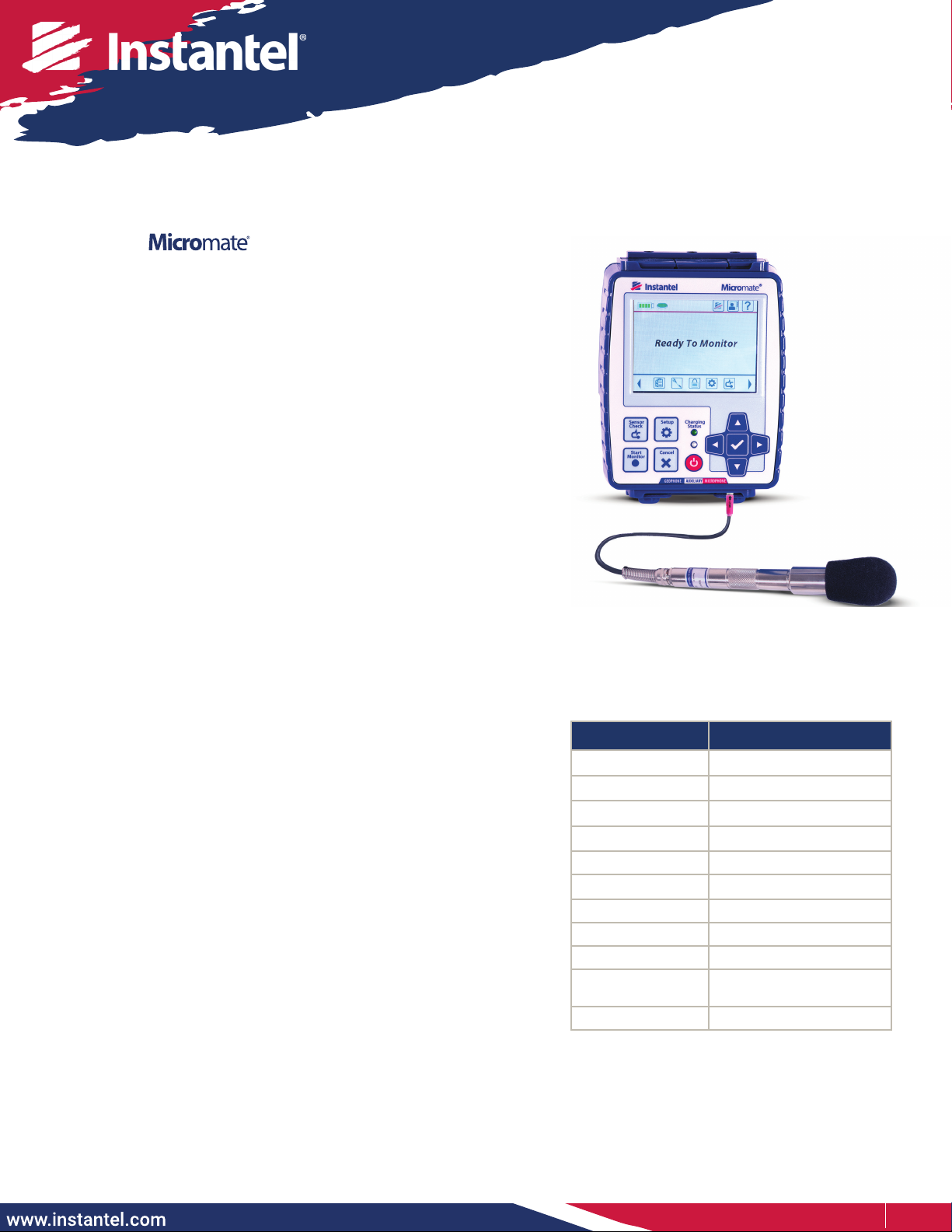
The Sound Level Microphone for the Micromate monitoring
unit, automates noise monitoring from building activities,
construction, trac, and mining operations. The Micromate
monitoring unit combines noise and vibration monitoring in
the same unit, making it a cost effective and exible device for
these applications.
The Sound Level Microphone meets the requirements for IEC
61672 Class 1, including A and C weighted specications and
has a measuring range from 30 dB to 140 dB with a Fast or Slow
response.
There are four record modes to choose from:
• Manual trigger
• Waveform (records up to 90 seconds, once triggered)
• Histogram (2 seconds to 30 minute intervals)
• Histogram-Combo (records both Histogram and Waveform
simultaneously)
Sound Level Microphone
Tools and Materials Required
Choose one of:
• Micromate ISEE Base Unit. . . . . . . . . . . . .(P/N: 721A2501)
• Micromate DIN Base Unit . . . . . . . . . . . .(P/N: 721A2601)
• Micromate Swedish Blasting Base Unit . . .(P/N: 721A3601)
• Micromate Swedish Pile Driving Base Unit. .(P/N: 721A3801)
• Sound Level Microphone . . . . . . . . . . . . .(P/N: 721A2301)
(stand and windscreen included)
• Extension cables, as required
10 m (33 ft). . . . . . . . . . . . . . . . . . . . (P/N: 721A0803)
30 m (100 ft) . . . . . . . . . . . . . . . . . . .(P/N: 721A0801)
75 m (250 ft) . . . . . . . . . . . . . . . . . . .(P/N: 721A0802)
Custom Extension Cable Kit . . . . . . (P/N: 721A3201)
• THOR software . . . . . . . . . . . . . . . . . . (free version)
• THOR Advanced software . . . . . . . . . . . . . (P/N: 72300201)
• A choice of three optional eld calibration devices:
- Delta OHM HD9101 Class 1
- Brüel & Kjaer Sound Calibrator Type 4231
- Rion NC-74 Sound Calibrator
Range of Applications
• Construction
• Mining
• Building Activities
• Trac
• Quarries
Specications
Field Values
Response Standard IEC 61672 Class 1
Frequency Weighting A-Weight or C-Weight
Response Fast (125 ms) or Slow (1 s)
Frequency Range 10 Hz - 20 kHz
Amplitude Range 30 dB to 140 dB max 160 dB
Trigger Levels 33 dB to 140 dB
Sample Rates 1,024 - 4,096 S/s
Resolution 0.05 dB (display limit 0.1dB)
Cable Length 2 m (6.5 ft)
Maximum Cable
Length 75 m (250 ft)
Temperature Range -10° to 50°C (14° to 122°F)
Note: Micromate units with serial numbers below 8000 require a factory update to support the Sound Level Microphone.
for the Monitoring Unit
2 / 5Instantel
Micromate Monitoring Unit Setup
1. On the Micromate monitoring unit keypad, press the Power button.
Note: To navigate the menus, use the arrow keys followed by the checkmark key or tap on the touchscreen display.
2. Press the Setup key then tap View/Edit Current Setup.
3. Tap Active Sensors until either Microphone or Geophone/Microphone is selected.
4. Tap Microphone Type until Sound Level is selected.
5. Select the desired Record Mode (Waveform Manual, Waveform, Histogram or Histogram-Combo).
6. Tap Trigger Level, then tap Microphone Trigger until Enabled is selected.
7. Tap Trigger Level, then swipe up or down on the spinner wheel or use the arrow keys.
8. Press the Checkmark key, this prompts you to save any changes. Use the Checkmark key to save the changes
or the Cancel key to cancel the changes and return to the previous screen.
9. Tap Response Time to toggle between Fast=125 ms (milliseconds) or Slow=1 s (second).
10. Tap Frequency Weighting to toggle between either A (A-Weight) or C (C-Weight).
11. Tap LN1 then swipe up or down until the desired value is reached.
12. Tap LN2 then swipe up or down until the desired value is reached. (Note: LN2 must be greater than LN1)
13. Tap either the Save icon on the touchscreen display or press the Cancel key for a prompt to save the
changes to a Setup File.
14. Select the Checkmark and then Save to Current File/Overwrite File.
15. Perform steps 13 and 14 a second time for the higher level settings.
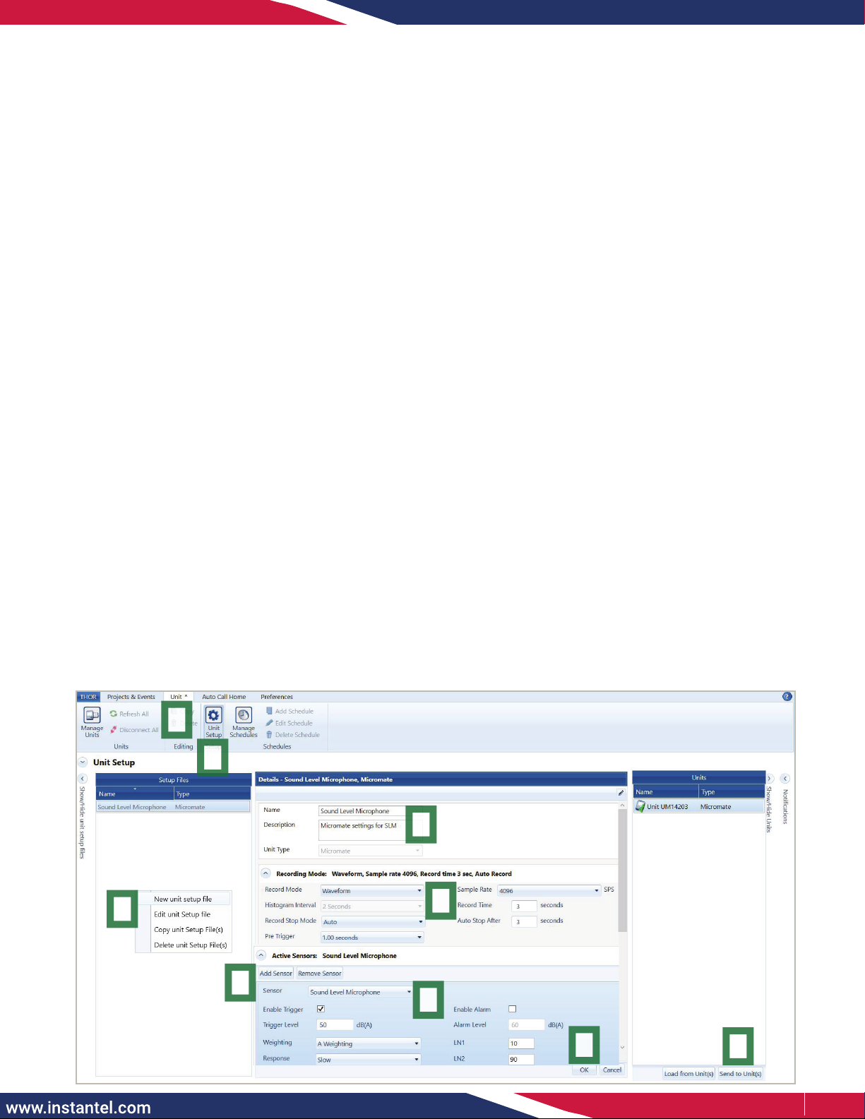
THOR Software Setup
The Sound Level Microphone for the Micromate monitoring unit can be congured using THOR software and then sent
to the connected unit.
1. Within the THOR software, click on the Unit Tab.
2. Click on the Unit Setup icon.
3. In the Unit Setup section, right-click and select New Unit Setup File.
4. Fill in the details and select Unit Type: Micromate.
5. Select the desired Record Mode and ll in the recording details.
6. Under Active Sensors, click on Add Sensor.
7. Under Sensor select Sound Level Microphone.
8. Fill in any Trigger details for Trigger level, Weighting, Response, LN1 and LN2 and click OK. In this section
you can also congure the external alarm.
9. Select the Micromate unit and click Send to Unit(s) to send the conguration le to the Micromate unit.
1
2
3
4
5
89
7
6

3 / 5Instantel
Field Calibration
The Micromate monitoring unit provides an option to calibrate the Sound Level
Microphone in the eld. A eld calibration only uses one reference signal of 94 dB
at 1 kHz. (The Brüel & Kjaer Sound Calibrator Type 4231 is also capable of generating
a 114 dB signal, make sure you set the device to 94 dB at 1 kHz.) A successful eld
calibration will store the values for Sound Pressure, Gain and Offset on the hardware
of the microphone, if there is an error during calibration, no values are overwritten.
In this case you can either try again or have the Sound Level Microphone calibrated
at Instantel or one of its authorized calibration facilities. Reports generated by
the Micromate monitoring unit will specify the serial number, calibration date and
calibration method.
Example:
Factory Calibration: UA12345, January 1, 2022 by Instantel
Field Calibration: UA12345, January 1, 2022 by Field Calibration
Note: Swapping Sound Level Microphones from one Micromate unit to another Micromate unit is permitted. As
calibration values are stored on the Sound Level Microphone, this will not impact any Micromate unit settings.
Field Calibration Procedure
1. Turn on the Micromate unit and connect the Sound Level Microphone, then press the Setup key on the unit.
2. Tap Maintenance Menu then scroll down and tap Calibrate Sound Level Microphone.
3. Follow the eld calibration device’s operator instructions to properly join the microphone with the eld
calibration unit. Set the reference to 94 dB at 1 kHz then turn the calibrator on.
Note: When using either of the three 94 dB eld calibrators, it is recommend that the ambient noise be at least 30 dB
lower than this reference signal.
For additional information please see https://www.pcb.com/Contentstore/mktgcontent/WhitePapers/
WPL_36_Acoustic_methods_calibration_PCB.pdf
4. Tap the Calibrate button on the Micromate monitoring unit screen.
5. Tap the Checkmark key to conrm the Proceed with calibration popup box. This will display Running Calibration.
6. When the calibration is nished, the Micromate unit will display Field Calibration Complete along with the
values for the measured Sound Pressure, Gain, and Offset.
7. In the Field Calibration Complete conrmation box, tap the Checkmark key.
Important Notes:
•
Only use an Instantel recommended calibration device (see the Tools and Materials Required section).
• Remove the microphone’s windscreen
before
attaching it to the field calibration device, as this can
impede proper calibration.
• Slide the Sound Level Microphone into and out of the eld calibration device
without
twisting either end.
• Before reinstalling the Sound Level Microphone in the eld,
hand-tighten
the microphone’s housing
extension and cap.
Calibration
The Sound Level Microphone
must be sent
to a manufacturer certied calibration facility, or Instantel headquarters
for calibration. Please visit our calibration facility locator at www.instantel.com. Instantel recommends calibrating all
Sound Level Microphones once a year and provides the Next Calibration dates on the unit and sensors. The factory
calibration process ensures that the microphone is performing as it was designed and accurately measuring
according to the IEC 61672 Class 1 standard.
Using a manufacturer certied facility ensures the proper procedures are followed when calibrating your
microphone. This removes any uncertainty associated with the reliability and measurement accuracy of your
microphone. It also helps ensure the integrity of the measured recorded events if they are ever called upon as
evidence in a court of law. Using unauthorized facilities may have negative legal consequences if the reference
equipment is not traceable, the proper procedures are not followed or if the certication documents are incomplete.
Please visit our calibration facility locator at instantel.com.
Note:
Field calibration is not
as precise as factory
calibration.
The Field Calibration
Procedure will change
the date and overwrite
the factory calibration
values.
The tracability will then
be linked to the Field
Calibration device.

4 / 5Instantel
Installing the Sound Level Microphone Stand
(See also Section 14.4. of the Micromate Monitoring Unit Operator Manual)
The microphone installation procedures are based on ISEE eld practice guidelines for blasting seismographs.
This section illustrates the installation procedures recommended by Instantel. Your particular monitoring activities
may employ one, or a combination of all, of the following procedures.
The Sound Level Microphone is supplied with a 3-piece microphone stand. The top section has a clip to hold the
microphone, the extension section is threaded at both ends and the bottom section is pointed to assist in the
installation. When the three pieces are assembled, the microphone stand is approximately 0.8 m (33 in) tall. Additional
extension sections can be purchased if required. (Microphone Stand Extension Rod, P/N: 400-720020-000)
Stand Installation Steps:
1. Assemble the microphone stand at the desired location (see Figure 1). Section 1 has a pointed tip to drive the
stand into the ground. Section 2 has a male and female thread. Screw in the female threaded end of section 2
into the male threaded end of section 1. Section 3 contains the microphone clip. Screw in the female threaded
end of section 3 into the male threaded end of section 2.
2. Push the pointed end of the microphone stand into the ground. If the ground is too hard, use a rubber mallet
to install the microphone stand.
Note: Do not use a metal hammer or other hard object as it may damage the top of the microphone stand.
3. Attach the windscreen to reduce false triggering caused by wind.
4. Install the Sound Level Microphone in the clip at the top of the microphone stand and point the microphone
in the direction of the noise source.
5. Ensure that the microphone cable is securely attached to the Micromate unit.
6.
Press the Sensor Check key on the Micromate unit ensuring the microphone is properly attached and has
passed
the Sensor Check. If the Sensor Check fails, ensure the ambient noise is at a minimum and repeat the test.
Figure 2.
Soft Ground Installation
Figure 3.
Hard Ground Installation
Figure 4.
Installing the Microphone
Figure 1.
3-Piece
Microphone Stand
Section
1
Section
2
Section
3
Setting Up the Sound Level Microphone
1. If required, assemble the stand (see Installing the Sound Level Microphone Stand below).
2. Point the microphone in the direction of the sound or noise source.
3. Place the windscreen on the end of the microphone.
4. Connect the microphone to the Micromate unit by aligning the red end of the connector with the indicated
red microphone port.
5. Make sure the Micromate unit has the proper Setup File (see THOR Software Setup on page 2), then
perform a Sensor Check by pressing the Sensor Check key on the keypad.

5 / 5Instantel
721U2301 Rev 05
© 2022 Xmark Corporation. All Rights Reserved. Design, features, and specications are subject to change without notice.
INSTANTEL, INSTANTEL LOGO, and MICROMATE are trademarks of Xmark Corporation, or an aliate thereof.
Warranty
Instantel products come with a limited one-year warranty against defects in materials or workmanship unless otherwise
stated. The warranty begins on the date of shipment from the Instantel factory to the customer and is subject to certain
exclusions and conditions as stated below. Monitoring units and sensors will have the warranty extended for a second year
if they are returned to the Instantel factory for service and calibration within 30 days of the ‘Next Calibration’ date printed on
the calibration label located on the product.
If, within a period of one year from the date of shipment to a customer, the instrument fails to perform in accordance
with Instantel’s published specications under normal use and operating conditions, it will be repaired or replaced at the
sole discretion of Instantel free of charge. Components subject to fair wear and tear in regular use, as solely determined
by Instantel, are excluded from this coverage. This warranty will not apply if the damage or malfunction occurs due to (i)
adjustments, additions, alternations, abuse, misuse or tampering of the instrument; (ii) instrument operation or use contrary
to the operating instructions; (iii) power uctuations; or (iv) any other cause not within the cause or control of Instantel. If
inspection by Instantel fails to disclose any defect covered by this limited equipment warranty, the instrument will be repaired
or replaced at customer’s expense and Instantel’s regular service charges will apply. This warranty is non-transferable.
Any shipments returned directly to Instantel must have prior approval, and all packages must display the Return of Material
Authorization (RMA) number issued by Instantel. Shipping charges to Instantel’s factory will be paid by the customer and
return shipment to the customer will be paid by Instantel.
To protect your warranty, you must complete and return a Warranty Registration Certicate, or complete the online Warranty
Registration Form, within ten days of purchase. Products will be assumed out of warranty if no warranty card is on le at
Instantel. Retain this warranty statement and the proof of purchase for your records.
Except for the foregoing limited equipment warranty, Instantel makes no other warranties and hereby disclaims and excludes
all other warranties, whether statutory, express or implied, whether arising under law or equity or custom or usage, including
any implied warranty of merchantability, tness for a particular purpose, non-infringement, satisfactory quality, or quiet
enjoyment, and any warranty that the product supplied may not be compromised, or that the product will in all cases provide
the function for which it is intended.
EC Warning
This is a Class B product. In a domestic environment this product may cause radio interference in which case the user may
be required to take adequate measures.
This manual suits for next models
1
Table of contents
Other Instantel Microphone manuals


Popular Microphone manuals by other brands

Devine
Devine BM-1000 user guide

Sony
Sony ECM 330 operating instructions

Mobility Sound
Mobility Sound C600-M12 quick start guide

ABL electronic
ABL electronic USB 2.0 Camera Microphone none user guide

Extron electronics
Extron electronics VoiceLift VLP 202 Setting up

Opvimus
Opvimus DC-700ETH operating instructions


