Intec FORCE 5150 User manual

Instruction Manual
Insulation blowing machine
Original Language –English
Intec — 4040 Kodiak Court, Frederick, CO 80504 USA
T: 303-833-6644 Web: www.inteccorp.com Email: info@inteccorp.com
T: 800-666-1611 Rev Date: 20181202

Instruction Manual | 1
T: 303-833-6644 or 800-666-1611
www.inteccorp.com
Original Language - English
Introduction
Thank you for purchasing an Intec insulation system. Since 1977, both professional contractors and
do-it-yourself equipment users have looked to Intec as the industry leader in the design and
manufacture of innovative, portable, professional grade insulation blowing equipment. Now many of
these individuals are also profiting thru the use of our truck mounted, high production gas blowing
machines and high powered vacuums –powered by either gas or electric. All Intec systems are
Engineered for High Productivity and Built-to-Last for High Value Generation. At Intec, we take pride in
making your job as easy and profitable as possible.
The right system for your needs: Intec strives to provide you with the best combination of portability,
functionality, and installation versatility to surpass your desired success.
•FORCE BLOWING MACHINES –Powered by Electric, Gas, or Diesel: From lightweight
polyethylene units with removable hoppers, to truck mount units with increased production rates and
installation versatility, all of our durable systems are made to maximize your profit generating
potential.
•VORTEC VACUUMS –Powered by Gas or Electric: Engineered for High Productivity and Built to
Last for High Value Generation, Intec’s VORTEC high powered vacuums provide the highest value
offered in today’s marketplace. With various sizes and gas or electric power options, we have a
vacuum that will enable you to profitably grow your business.
Best-in-class Customer Service: Total ease of use extends beyond your initial purchase of an Intec
system to your evolving needs thru the entire lifecycle. Both before and after the sale service is
important to keep you running at peak operating capabilities. Intec’s technical team provides
installation assistance in addition to maintenance suggestions and trouble-shooting support. In
addition to blowing machines, Intec produces a range of accessories that will increase your
productivity when dense packing, damp spraying, and installing net and blow.
Thank you for partnering with Intec. We appreciate the confidence and trust you have placed in us,
and wish you many profit-generating opportunities!
Ray Lavallee
President, Intec

Instruction Manual | 2
T: 303-833-6644 or 800-666-1611
www.inteccorp.com
Original Language - English
Table of Contents
INTRODUCTION ........................................................................................... 1
SYMBOLS.................................................................................................... 3
SAFETY FIRST ............................................................................................... 3
HOW THE SYSTEM WORKS................................................................................. 4
System Set-Up:...................................................................................................................................................... 7
System Operation: ................................................................................................................................................. 9
Reprogramming Intec’s Long Range Transmission wireless remote ............................................................................10
MAINTENANCE ............................................................................................ 11
TROUBLESHOOTING....................................................................................... 13
SPECIFICATIONS…………………………………………………………………………………………………………….………….18
ELECTRICAL DRAWINGS ................................................................................... 19
MAKING A CLAIM FOR DAMAGE OR LOSS ............................................................... 20
WARRANTY ................................................................................................ 21

Instruction Manual | 3
T: 303-833-6644 or 800-666-1611
www.inteccorp.com
Original Language - English
Symbols
SYMBOL
SYMBOL
MEANING
Danger
Indicates an imminently hazardous situation, which, if not avoided,
will result in death or serious injury.
Warning
Indicates a potentially hazardous situation, which, if not avoided,
could result in death or serious injury.
Caution
Indicates a potentially hazardous situation, which, if not avoided,
may result in minor or moderate injury.
Safety First
Prior to working on the equipment, shut HONDA motor and remove key. Failure to
do so could result in injury or death.
Never operate equipment with safety guards removed.
Never operate equipment with known mechanical issues or if machine is vibrating
extensively –additional damage can potential safety issues can occur.
Never operate equipment while standing in water as electrical shock may result.
Proper Protective Equipment - When working with insulation, always wear a long
sleeve shirt, gloves and a hat. Wear goggles or safety glasses for eye protection.
Wear a mask for respiratory protection. Hearing protection is also suggested.
Never put your hands into the hopper, machine outlet, or near any moving part
while the machine is operating.
Keep tools and foreign objects out of the hopper.
Never leave the machine unattended during operation. Power down the machine
and turn off HONDA engine when unattended.
Never operate the equipment with the access panels off, possible injury may occur.
Prior to use, inspect wired remote cord to ensure no damage exists. If damage
exists, correct prior to use.

Instruction Manual | 4
T: 303-833-6644 or 800-666-1611
www.inteccorp.com
Original Language - English
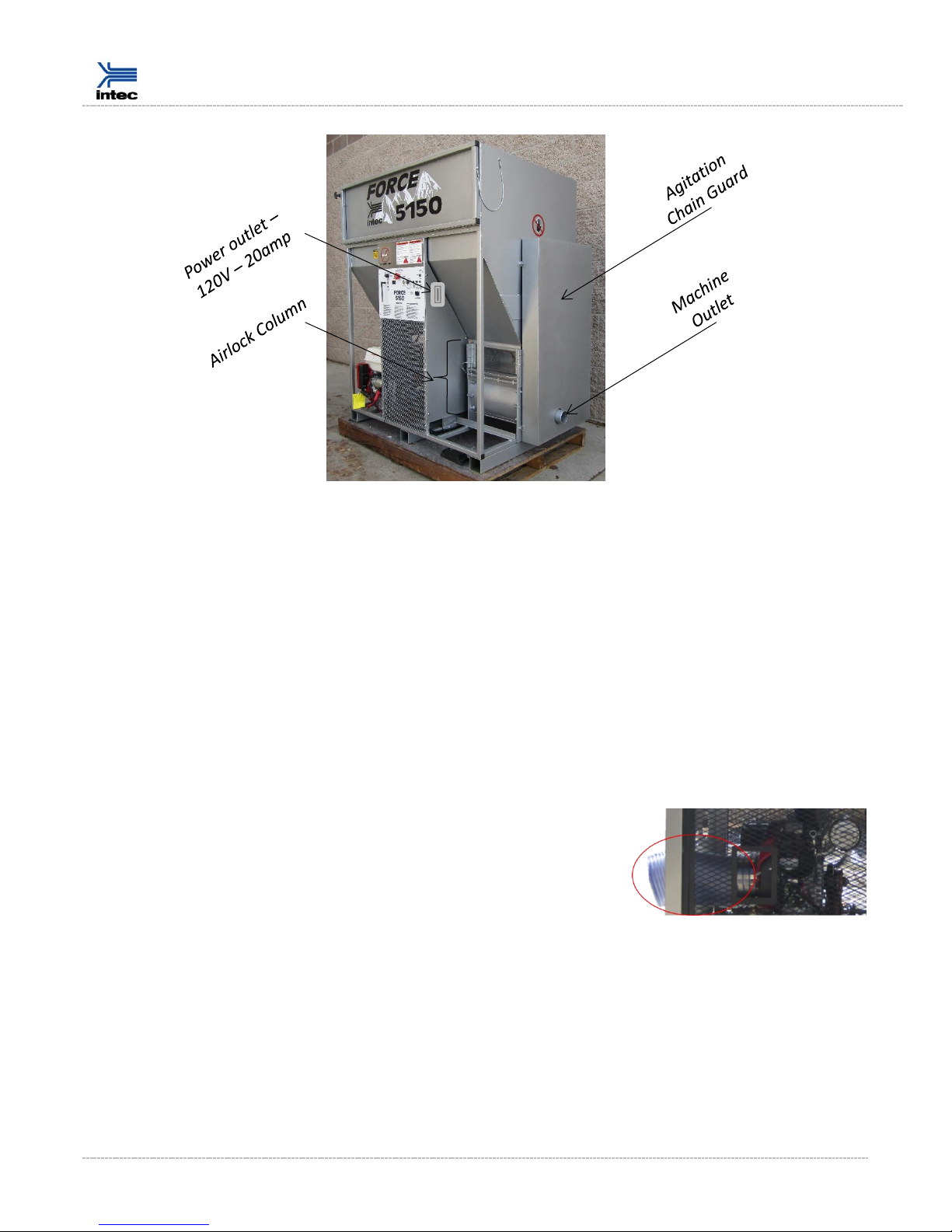
How the System Works
OVERVIEW: Cellulose, Fiberglass, or Stone Wool insulation is loaded into the hopper. The agitation
system is the first step in processing the insulation while moving towards the airlock column. Once in
the column, insulation is processed additionally by the shredder bar. It then moves through the slide
gate and into the airlock where the insulation is fed into the airstream created by the blower system.
Insulation is discharged from the airlock, through the machine outlet, and into the hose. The insulation
is further conditioned as it travels through the hose.
Instruction Manual | 5
T: 303-833-6644 or 800-666-1611
www.inteccorp.com
Original Language - English
An introduction to key components of the system follows:
Electrical Panel: The electrical panel, combined with the wireless and/or wired remote, provides
operation of the machine.
Power Outlet: The on-board generator is oversized to both power the system in addition to providing
an additional 120V –20amps to power a wall spray pump, scrubber, electric vacuum, or charge a tool.
Loading Platform: The loading platform acts as a shelf to support the bag of insulation being loaded
into the hopper.
Hopper: The hopper contains the insulation being fed into the agitators.
Engine Fresh Air Inlet Hose: The Engine Fresh Air Inlet Hose provides
cool clean air from outside the truck / trailer to ensure that your
HONDA engine is appropriately cooled. The clean air from outside
also prevents fibrous particles from being pulled into your engine’s
cooling fins. Utilize Intec’s Air Inlet mounting plates to attached the
hose coming from machine to fresh air.
NOTE: Never run engine w/out the air inlet hose attached. Doing so will draw insulation into your
engine’s cooling fins which will drastically reduce the life of your engine.

Instruction Manual | 6
T: 303-833-6644 or 800-666-1611
www.inteccorp.com
Original Language - English
Filter –blower: Ensures clean air is being used by blowers for intake and cooling. Filtered air, free of
insulation dust, prolongs the blowers’ longevity and trouble-free operation.
Filter - generator: The generator inlet is equipped with a filter to ensure clean
air is used to cool the generator. Clean air free of insulation particles
prolong’s the generator’s life.
Dual Agitators: The agitators condition the fibrous insulation. The
configuration of the agitators enable high production rates, appropriate
insulation conditioning, and transport of the insulation into the airlock.
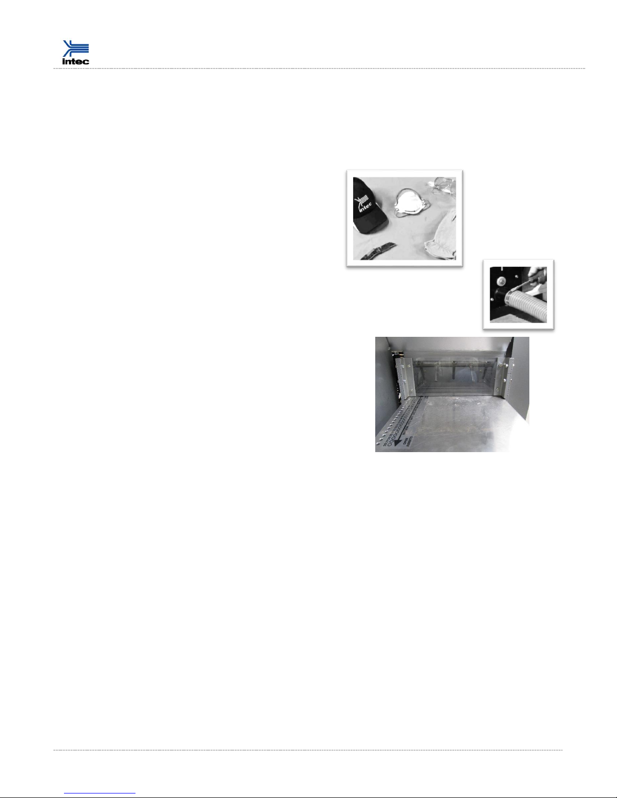
Shredder Bar & shredder box window: The shredder bar spins quickly to
provide final insulation processing. The shredder box window can be removed quickly to enable access
to the shredder bars if a need exists to remove foreign materials that have become entangled in the
shredder bars.
CAUTION: Always ensure machine is off and cannot be restarted when accessing the shredder box.
Slide Gate: The slide gate allows insulation to fall into the airlock. The slide gate is opened fully during
typical operation. Close the gate slightly to increase the conditioning of the insulation and alter ratio of
insulation to airflow.
Gate Pin Setting: Place the pin into the desired slide gate hole to ensure the gate stays in desired
position during operation.
Airlock: The airlock transfers the insulation from the agitation system into the airstream without
coming into contact with the blowers. Insulation is discharged from the airlock into the hose.
Urethane Airlock Seals: Your FORCE 5150 includes Intec’s proprietary urethane airlock
seals for long lasting effectiveness. Proper airlock sealing allows for high production
rates and high pressures for effective wall fill applications.
Shredder Bar
Shredder Box
Window
Slide gate
Quick Access Airlock Door
Gate Pin
Setting

Instruction Manual | 7
T: 303-833-6644 or 800-666-1611
www.inteccorp.com
Original Language - English
Quick Access Airlock Door: By removing six bolts, the Quick Access Airlock Door can be opened on its
hinge to enable quick change of the airlock seals to ensure appropriate air sealing and peak
production.
Set up and Operation
System Set-Up:
INITIAL OPERATION
During initial operation, install the fresh air inlet for the HONDA GX390.
A. Engine Fresh Air Inlet mounting plates: These mounting plates enable
you to connect the 10” hose provided with your system (and connected
to the HONDA engine) to a fresh, clean air source outside of your
vehicle. Recommendation is to:
a. Cut a 10” diameter hole into the side wall or floor of your truck /
trailer. NOTE: be sure to cut in a non-load bearing area.
b. Mount the Outside Plate (on the outside of the truck) and Inside
Plate (on the inside of the truck) –sandwiching the wall or floor -- with four nuts.
c. Hose Ring: The Hose Ring will mount to the Inside Plate.
Inside Plate
Outside Plate
Instruction Manual | 8
T: 303-833-6644 or 800-666-1611
www.inteccorp.com
Original Language - English
Once mounted and hardware is tightened, you are ready to fasten the open side of the Fresh Air Inlet
to the 10” diameter hose.
Upon completion, you will now have fresh, clean air from outside your vehicle used to cool the HONDA
engine.
EACH TIME YOU UTILIZE BLOWING MACHINE
1. Obtain appropriate protective equipment.
2. Attach hose to machine outlet using a hose clamp.
3. Open slide gate & place pin in desired opening.

Instruction Manual | 9
T: 303-833-6644 or 800-666-1611
www.inteccorp.com
Original Language - English
System Operation:
1. Energize System
a. Pull EMERGENCY STOP out (i.e. into the ON position).
b. Start HONDA engine
i. Turn fuel valve in the ON position.
ii. Place choke in the ON position if
engine has not been running.
iii. Turn key to START position and
release once engine starts.
iv. Reduce choke when engine is
warming up until choke is in the OFF
position.
v. Move engine throttle to FULL
position.
NOTE: ENGINE HAS TO BE RUNNING AT FULL THROTTLE
FOR GENERATOR, BLOWERS, & FORCE 5150 ELECTRICAL
SYSTEM TO FUNCTION APPROPRIATELY.
2. Rotate the ROTARY CONTROL SELECTOR
SWITCH to the desired method to operate
system.
a. WIRELESS REMOTE
i. Operate system thru Intec’s
Long Range Transmission
wireless remote.
b. WIRED REMOTE
i. Operate system thru
wireless remote with Intec’s
exclusive long lasting
urethance jacked controls.
ii. Plug wired remote into the
REMOTE QUICK
DISCONNECT female connector.
Note: Unplug the wired remote when not using the wire remote to operate the FORCE 5150. When
unplugging, pull the metal tab back and turn ¼ turn, then remove male end from the REMOTE QUICK
DISCONNECT female connector.
c. OFF
d. BLOWER
i. Operate system thru its control panel. Blower(s) are activated in this setting.
e. BLOWER & AGITATOR
airfilter
CHOKE ON
FUEL ON
THROTTLE

Instruction Manual | 10
T: 303-833-6644 or 800-666-1611
www.inteccorp.com
Original Language - English
i. Blower(s) and agitator are activated in this setting. Note that the blower needs
to be on for the agitator to come on.
Please note the following:
BLOWER must be running for the agitator to operate.
To obtain maximum blower output, ensure that:
VARIABLE SPEED is in the off position, and
AUXILIARY BLOWER is in the ON position.
3. Load Insulation -- Remove packaging material from around insulation and load into hopper.
Reprogramming Intec’s Long Range Transmission wireless remote
Transmitter
1. Get to the underside of transmitter.
a. Transmitter may be in jacket that allows for fitting onto arm or hose. You may desire to
remove transmitter from jacket.
b. Remove small piece of black tape on back of transmitter.
c. Stick a paperclip into the small hole and hold button down for 7 to 14 seconds to enable
wireless transmitter to select a diffent chanel.
Receiver
1. Ensure HONDA motor is running at full throttle.
2. Rotate the ROTARY CONTROL SELECTOR SWITCH to the WIRELESS selection.
a. Note: The LEARN BUTTON LED light will flash steadily, while the SYNC-LED will not be lit.
3. Press the LEARN BUTTON and release.
a. the SYNC-LED will flash rapidly, while the LEARN BUTTON LED light will remain solid.
4. On the wireless remote transmitter:
a. Press and release the BLOWER button
b. Press and release the AGITATOR button
5. Wait 17 seconds for the receiver to reset.
6. When the receiver has been reset, the LEARN BUTTON LED light will flash steadily, while the
SYNC-LED will not be lit. COMPLETE –The wireless receiver has now been programmed to
accept the transmitter’s signal.

Instruction Manual | 11
T: 303-833-6644 or 800-666-1611
www.inteccorp.com
Original Language - English
Maintenance
Preventative maintenance will provide for many years of trouble-free use.
HONDA GX390
Please consult the HONDA manual for appropriate engine maintenance.
A few quick items related to the engine:
1. Initial oil change required after 20 hours of use
a. Recommend to use 5W-30 oil; consult manual for ideal oil in your operating region and
typical temperature ranges.
2. Clean engine air filter weekly.
3. Run engine at full throttle for appropriate operation of the FORCE 5150 blowing machine.
Cleaning
Clean the interior and exterior of the machine weekly by wiping with a rag and/or blowing with
compressed air; this will help maintain the longevity of the mechanical components in addition to the
system’s finish. The machine has been designed to work in a dusty environment. However, without
periodic cleaning and maintenance, the performance of the machine will decline potentially leading to
failure.
Filters
Blower: Recommendations are to clean the blower inlet air filter at the beginning of each day. This
foam filter can be cleaned by simply taking out of its holder, shaking insulation and foreign materials
out of the filter, and then re-installing into its holder. Replacement filters are available at Intec.
Generator: Recommendation is to clean the generator air filter on a monthly frequency.
Step 1 –remove filter cover from generator

Instruction Manual | 12
T: 303-833-6644 or 800-666-1611
www.inteccorp.com
Original Language - English
Step 2 –Remove filter from its cover. Please use caution as filter is thin; avoid tearing.
Step 3 - Clean filter -- shake, used compressed air, or wash with water. Re-install into system.
Wired Remote Cord
Ensure your wired remote cord is in good operating condition with the black jacket not worn and no
individual wires showing. If an individual wire is showing, or if wires were pulled from the transmitter’s
jacket or male plug which inserts into the control panel, correct prior to use.
Airlock and Seals
The airlock assembly is one the most important items to keep in good condition. Foreign objects in the
airlock can cause damage and reduce the machine’s production. Seal failure is the most common
airlock assembly failure. Seal failure prevents the airlock from holding the proper pressure. Seal
failure will reduce the machine’s production. A machine with seal failure will have air blow out of the
airlock into the hopper, reducing the amount of air exiting the machine outlet. It is recommended to
visually inspected seals each week to ensure proper running condition. Replace airlock seals if a cut or
tear is evident. Airlock seals should be replaced every 300 hours of operation, or once per year. Visit
www.inteccorp.com or contact Intec for replacement instructions.
Chain
Clean and lubricate the chains once per year. Use a dry lubricant when lubricating the chain; do not
use oil as oil will attract foreign particles like dust to chain. If the machine is often used in dusty
conditions, then clean and lubricate the chain more frequently than once per year.
Belts
Belts will stretch over time. New belts will stretch relatively quickly and limited additional stretching
over use. The FORCE 5150’s belts are properly tensioned when leaving the factory, yet stretching will
require you to re-tension the belts.
Generator: It is important for the generator to run at full operating speed (~3600 rpms); a slipping belt
will reduce the generator’s speed which will not allow for proper operation of the system. To tighten
the generator’s belt, simply loosen each of the four bolts holding the generator to the FORCE 5150’s
frame, push the generator in the direction away from the HONDA motor to tension the belt. When the
belt has approximately ½” of play, then tighten the generator into place.

Instruction Manual | 13
T: 303-833-6644 or 800-666-1611
www.inteccorp.com
Original Language - English
TroubleShooting
Problem
Likely Cause
Remedy
HONDA GX390 does not start
Fuel switch in off position
Place lever in the ON position
by moving to the right towards
engine.
Fuel not in gas tank
Refill gas tank with Premium
Unleaded gasoline.
Emergency stop button has not
been pulled out.
Pull out emergency stop
bottom.
Battery is dead.
Charge or replace battery.
Blower(s) does not run.
HONDA is not running at full
throttle.
Move throttle to the full HIGH
position.
Auxiliary Blower’s circuit
breaker needs to be in the ‘on’
position.
Place Auxiliary Blower’s circuit
breaker in the ‘on’ position.
Auxiliary Blower switch is OFF.
Place auxiliary blower switch
into the ON position.
Hose may be disconnected
from one-way valve to blower.
Contact Intec for appropriate
troubleshooting.
Worn brushes in blower motor.
Have a qualified technician
replace blower motor.
Agitator does not run.
Blower has to be on for agitator
to come on.
Turn blower on.
Agitator circuit breaker needs
to be in the ‘on’ position.
Place Agitator circuit breaker in
the ‘on’ position.

Instruction Manual | 14
T: 303-833-6644 or 800-666-1611
www.inteccorp.com
Original Language - English
Problem
Likely Cause
Remedy
Machine is on, yet no material
comes out of hose.
Slide gate is closed.
Open slide gate.
Insulation blockage in hose.
Turn system off, remove hose
and clear blockage.
Blower is off.
Turn blower on.
Air pocket in hopper is
preventing insulation from
feeding into agitators.
Shut HONDA, press in E-Stop.
Redistribute insulation material
inside hopper.
Airlock seal is worn.
Inspect airlock seals for cuts
and wear. Have a qualified
technician replace airlock seals.
Airlock has an obstruction
preventing insulation from
exiting.
Shut HONDA, press E-stop in,
then remove obstruction.
Variable Speed is ‘on’ and
Variable Speed Setting is below
100%, yet still a lot of air flow.
Auxiliary blower is on.
Place the Auxiliary Blower
Circuit Breaker in the ‘off’
position.
Variable Speed Setting needs to
be decreased.
Reduce Variable Speed Setting
closer towards zero.
Insulation exiting hose is
dribbling out.
Heavy insulation material.
Push slide gate in 1-2 holes.
Turn up variable speed on
Primary Blower.
Turn variable speed selector
switch to ‘off’ to allow for
maximum power on Primary
Blower.
Turn on Auxiliary Blower.
Kink in hose.
Straighten hose.
Airlock seal is worn.
Inspect airlock seals for cuts
and wear. Have a qualified
technician replace airlock seals.
Machine makes a banging noise
when agitator is operating.
Chain is loose.
Stop HONDA motor. Have a
qualified technician adjust chain
tensioner.
Adjust chain tensioner.

Instruction Manual | 15
T: 303-833-6644 or 800-666-1611
www.inteccorp.com
Original Language - English
Chain is not aligned with
sprockets.
Disconnect electrical power.
Have a qualified technician
realign chain and sprockets.
Problem
Likely Cause
Remedy
Wireless remote not controlling
system as desired. Pressing ‘on’
and blower or agitator not
turning ‘on’; or pressing ‘off’
and blower or agitator not
turning ‘off’.
Reception range less than
desired.
Make sure the trailer or truck’s
doors –especially the large door
in back -- are open to allow for
radio frequency waves to easily
enter and access the receiver in
the blowing machine.
Antenna in the down position.
Position the antenna into a
straight position vs. the 90
degree bend. This allows the
machine to act as a source to
gather the radio frequency
waves and enhances reception).
Install the optional antenna
extender. Contact Intec for
details.
Blower and agitator continue to
run and wireless remotes do
not control system.
Transmitter out of range from
receiver.
Move closer to system.
Transmitter battery needs to be
replaced.
Replace battery. Intec can
provide assistance with
instructions as beneficial.
Need to re-sync the receiver to
the transmitter.
Follow instructions provided in
manual.

Instruction Manual | 18
T: 303-833-6644 or 800-666-1611
www.inteccorp.com
Original Language - English
Specifications
Weight
FORCE 5150
825 lbs; 375 kg
Hopper size
31 cubic feet
Blowers –Quantity = 2
115 VAC, 13.4 amp, two stage for each blower
Motor
HONDA GX390 with electric start
Instruction Manual | 19
T: 303-833-6644 or 800-666-1611
www.inteccorp.com
Original Language - English
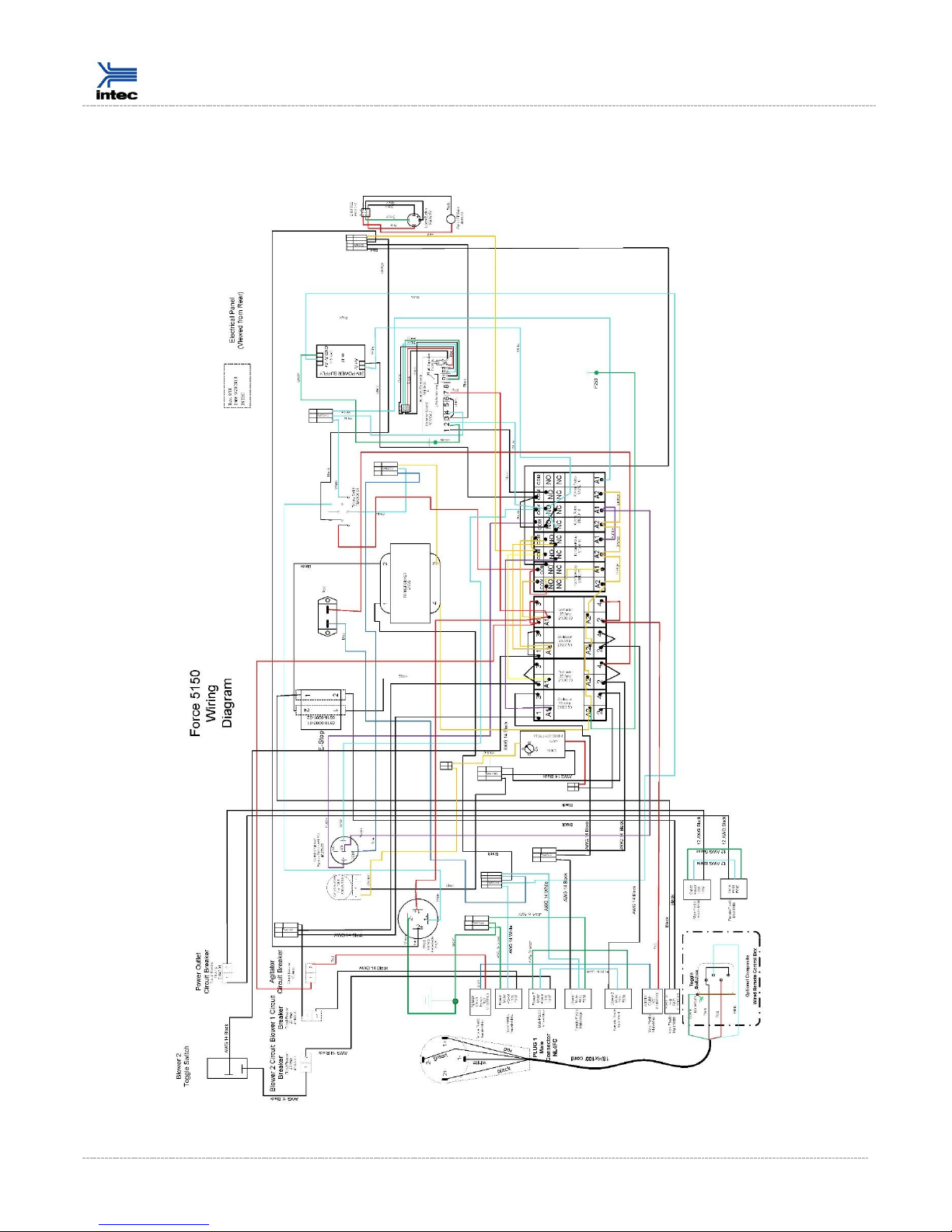
Electrical Drawings

Instruction Manual | 20
T: 303-833-6644 or 800-666-1611
www.inteccorp.com
Original Language - English
Making a Claim for Damage or Loss
Your Intec products were carefully packed and thoroughly inspected before leaving our factory. We
understand that damage to or defects with your system may unfortunately occur. Please inspect your
shipment carefully upon arrival and save the shipping containers and packaging materials in case of
damage.
The following table provides you with appropriate actions to take when certain issues are realized.
ISSUE
Action to Take
1
DAMAGE in Transit
A
Visible PRIOR to unpacking (Damage to carton or
packing material).
File Claim with appropriate freight
carrier.
B
Visible AFTER unpacking (Only apparent when
unpacked).
File Claim with appropriate freight
carrier.
C
Shortage (# containers does not agree to
transportation bill).
File Claim with appropriate freight
carrier.
When items leave our warehouse, the shipper assumes responsibility. It is the responsibility
of the consignee to file a claim. Proper documentation is necessary to support the claim.
Please inspect all items properly prior to signing for them.
2
Items received not correct
A
Incorrect items received.
Contact Intec Customer Service
B
Incomplete order received (not backordered).
Contact Intec Customer Service
303.833.6644 ext. 102
3
Issue within the warranty period
A
Troubleshooting (machine or part not operating as
intended).
Contact Intec Customer Service
B
Replacement part(s).
Contact Intec Customer Service
Intec can assist with troubleshooting your issue, and
can get you back up and running. If warranty parts are
required, a return material authorization (RMA) will be
issued by technical service.
4
Issue outside of warranty period
A
Replacement part, troubleshooting.
Contact Intec Customer Service
B
Need assistance from a service center.
Contact Intec Customer Service
303.833.6644 ext. 105
Shipping Department
Intec
4040 Kodiak Court
Frederick, CO 80504
phone: 303-833-6644, 800-666-1611
fax: 303-833-6650
website: www.inteccorp.com

Instruction Manual | 21
T: 303-833-6644 or 800-666-1611
www.inteccorp.com
Original Language - English
Warranty
It is expressly understood and agreed that no officer, agent, salesman or employee of the manufacturer
Intec (MANUFACTURER) has the authority to obligate the MANUFACTURER by any terms, stipulations, or
conditions not herein expressed; that all previous representations and agreements, either verbal or written,
referring to the machinery and equipment, which is the subject of this Warranty, are hereby superseded
and canceled, and that there are no promises or agreements outside of the Warranty agreement. Further-
more, the MANUFACTURER hereby disclaims any implied warranties of merchantability, or implied war-
ranties of fitness for a particular purpose.
With the above understanding, the MANUFACTURER provides the following one (1) Year Limited Warranty,
and no other, for its insulation blowing machines (MACHINES):
a) MANUFACTURER warrants to the original purchaser that the MACHINE is well made, of good material
and durable; but only if the MACHINE is operated and maintained in accordance with the Instruction
Manual. This Warranty is void if the MACHINE is not so operated and maintained, or if the MACHINE is
used for blowing materials other than those which are intended to be used with the MACHINE.
b) MANUFACTURER guarantees the MACHINE to be free from manufacturing defects at the time of
shipment, and to remain free from defects when operated under normal use, for a period of one (1) year
from the date of factory shipment, with the exception of the blowers, electrical and air lock components,
which are warrantied for a period of ninety (90) days from date of factory shipment.
c) This Warranty shall not apply to any MACHINE or component part which, in the opinion of the
MANUFACTURER, has been altered, subject to misuse, negligence, accident or operated beyond factory
rated capacity. All requested Warranty work should be performed at MANUFACTURER’s factory or by an
Authorized Factory Service Facility. Failure to have the Warranty work done at MANUFACTURER’S factory
or by an Authorized Factory Service Facility will void this Warranty. MANUFACTURER will bear full
responsibility to repair or replace, at its option, without charge to the original purchaser, any part that, in
the MANUFACTURER’S opinion, is found to be defective.
d) All parts claimed defective by original purchaser shall be returned, properly identified, to
MANUFACTURER’s factory or Authorized Factory Service facility, freight prepaid. All replacement, repaired
or non-defective parts will be returned to purchaser, freight collect. MANUFACTURER will supply
replacement parts prior to purchaser, freight collect. MANUFACTURER will supply replacement parts prior
to receipt of any parts claimed defective, only with the understanding that such replacement parts will be
shipped to purchaser at the then prevailing price of said part, C.O.D., freight collect. MANUFACTURER will
reimburse cost of any such part only after receipt and inspection, and finding said part defective.
e) MANUFACTURER’s liability is expressly limited to the repair or replacement of defective parts set forth in
this Warranty. All other damages and warranties, statutory or otherwise, being waived are original
purchaser as a condition of sale and purchase of said machines. Furthermore, the MANUFACTURER shall
not be liable for damages or delays caused by defective material or workmanship.
Table of contents
Other Intec Blower manuals


