Integrated M2M Technologies iLocate GPS AutoTracker AT850218 User manual


iLocate AT850218
2
www.gps.LenderSystems.com Copyright 2018
Document Revisions
Date
Version
Document changes
Author
Approvals
3/27/2018
1.15
Original release
C. Cochran
F. Simon
Table of Contents
1.0 Introduction
2.0 Hardware
3.0 Operation
4.0 Connections
5.0 Configuration Settings
6.0 LED light indicators
7.0 User Account –Tracking Events
8.0 Specifications
iLocate AT850218
3
www.gps.LenderSystems.com Copyright 2018
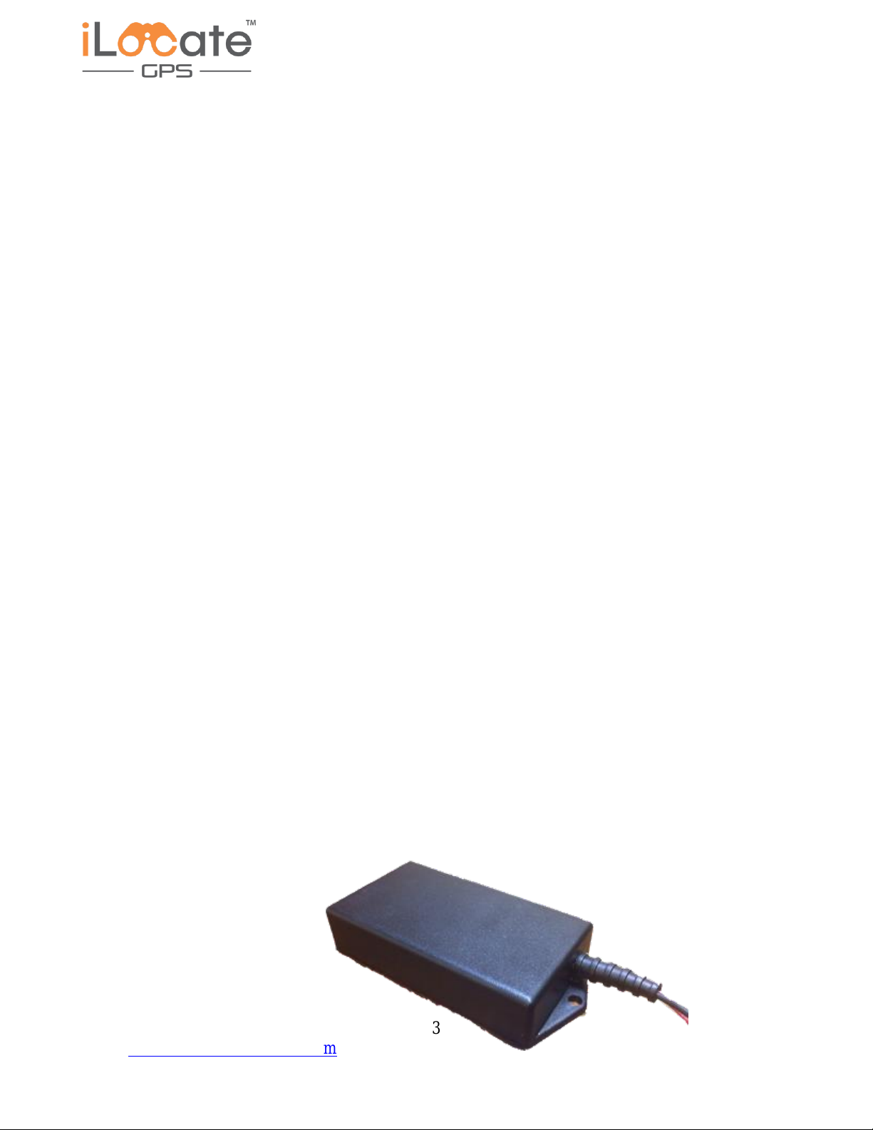
1.0 Introduction
The iLocate tracking product is a fully integrated electronic device for providing location and
status information of things by way of cellular radio network connection to the internet. This
iLocate tracking device includes a CAT-M1 cellular radio, GNSS GPS receiver, Bluetooth 5.0
BLE transceiver, three axis accelerometer, indicator lights, external data connection, and an ARM
Cortex M4 host controller.
2.0 Hardware
The device is powered by external direct current voltage and an internal back up battery. The
external voltage is also used to charge the internal battery.
The host controller manages all setups and communication with the integrated components as
well as providing user data cable connection for external controls, indicator lights and sensor
input/output.
The cellular radio is a shielded module with internal firmware for managing the CAT-M1
network connection, internet protocol data transfers, accessory features, and communication with
the application host controller. The cellular module transceiver uses and on board impedance
matched ceramic antenna.
The GPS receiver is a shielded module with internal circuitry for receiving satellite positioning
data. An internal controller parses the GNSS receiver data and converts the location information
to industry standard NMEA messages. The host processor collects the required data from the GPS
module and formats the location data to be sent over the cellular network to a server computer.
The accelerometer is a +/-2g, +/-4g, +/-8g, +/-16g, 3 axis sensor. The movement and orientation
data is available in up to 14 bit resolution. Interface with the host controller is by standard two
wire interface.
LED indicators are provide to show status of the operation of the device components. There are 4
green LEDs and 4 red LEDs.
The external connection is provide with a 6 pin connector. This connection is configured to
receive and transmit serial data. Other pins can be configured as input or output as required by
specific application requirements.
iLocate AT850218
4
www.gps.LenderSystems.com Copyright 2018
LED outputs
3.0 Operation
Connect the power cord to the +V supply of the vehicle. This will charge the internal
system battery when necessary. This iLocate GPS AutoTracker is designed to operate
with or without the DC power connected running on the internal battery when no +V
power is available. Allow the unit to charge several hours if it has not been charged
recently. The units will power up with the radio off, in standby state. The iLocate
AutoTracker will send a location data packet to the selected internet IP address and port
number. The IP address and port number will be set by an authorized service technician.
4.0 Connections
An external connection is provide with a 6 pin connector. This connection is configured
to receive and transmit data to an accessory device as required for specific use
applications. The connector pins can are configured as input or output as required by
specific application requirements. The settings are adjusted only by an authorized service
technician prior to delivery to the end user.
5.0 Configuration Settings
Configurations and settings are set for each application. These configurations are set by
an authorized service technician prior to delivery. No user adjustments are required.
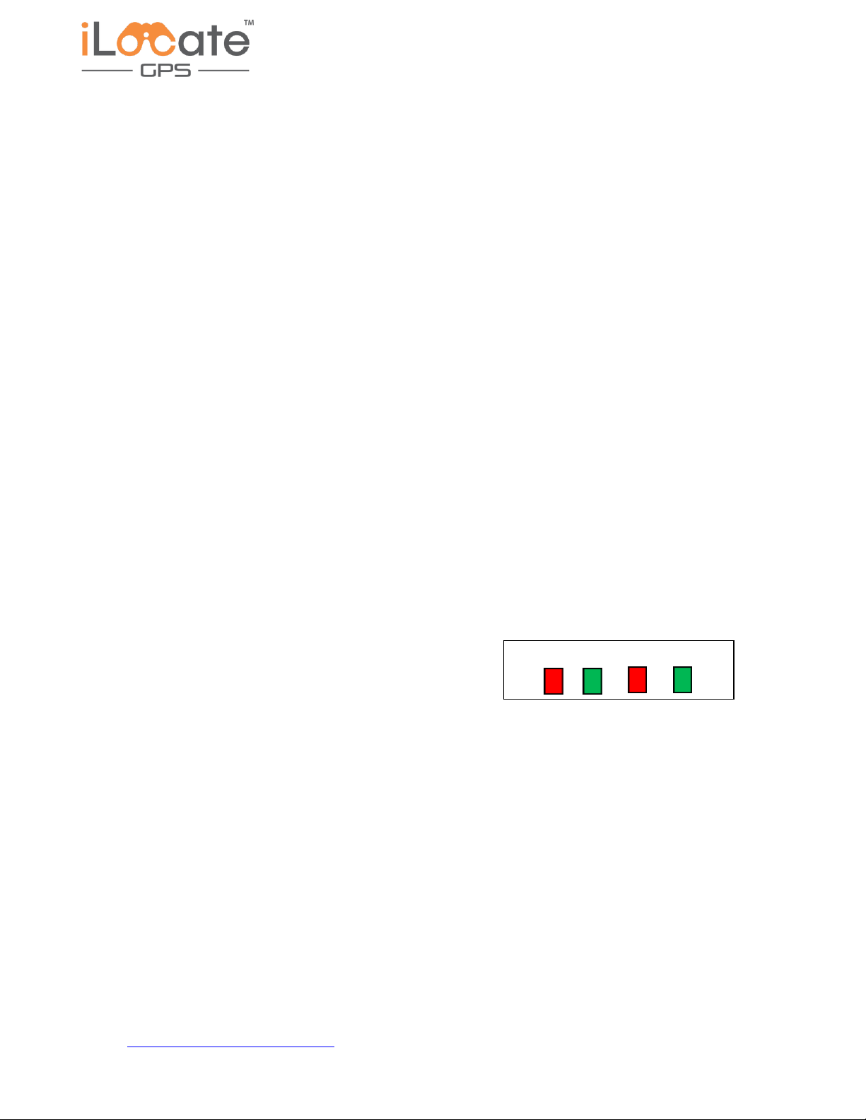
6.0 LED light indicators
LED indicators are provide to show status of the
operation of the device.
There are 4 green LEDs and 4 red LEDs.
Green LED 1 ON indicates the Cellular radio is in operation.
Green LED 2 Blink ON indicates the GPS has received a fix.
Green LED 3 TBA (To Be Assigned)
Green LED 4 TBA
Red LED 1 TBA
Red LED 2 TBA
Red LED 3 Blink ON indicates the motion sensor detected movement.
Red LED 4 TBA
Assignment of the LED functions is subject to change as application requirements are refined.

iLocate AT850218
5
www.gps.LenderSystems.com Copyright 2018
7.0 User Account –Tracking Events
User accounts are set up by the iLocate GPS customer service staff. Each user will be
assigned an account and provided with an account registration notification by email.
Download and install the app to a smartphone. The user will select a password and
Follow the instructions in the email to set up the
account and add the vehicle that is associated with
this account. The vehicle location and event status
will now be available in the App.
iLocate AT850218
6
www.gps.LenderSystems.com Copyright 2018
8.0 Specifications
iLocate GPS Specifications
Model: AT850218
Electrical Specifications
Input rating: 8.0 –20.0 VDC, resettable fuse, protected front end
Bands Supported: LTE cellular radio, CATM1 bands 4 and 13
DL/UL max: 300 kbps / 375 kbps
TCP, UDP, SMS, embedded SIM
Embedded CPU: 32 bit processor ARM Cortex M4
with Bluetooth 5.0 BLE transceiver
Embedded GPS Module: GNSS Receiver -160 to -167 dBm sensitivity
Embedded SIM: Gemalto MFF2
Accelerometer: 2g to 16g Tri-Axis
Mechanical Specifications
Operation Temperature: - 40 to + 85º Celsius
85% R.H. @ 50º C non-condensing
Dimensions: 2.25 x 5.0 x 0.95 in. (56 x 125 x 24mm)
Board dimensions 2.0 x 3.95 x 0.60in. (53.0 x 96.0 x 15.0mm)
Weight: 120 oz.
iLocate GPS Device
Trademark - iLocate GPS
User Manual - iLocate User guide
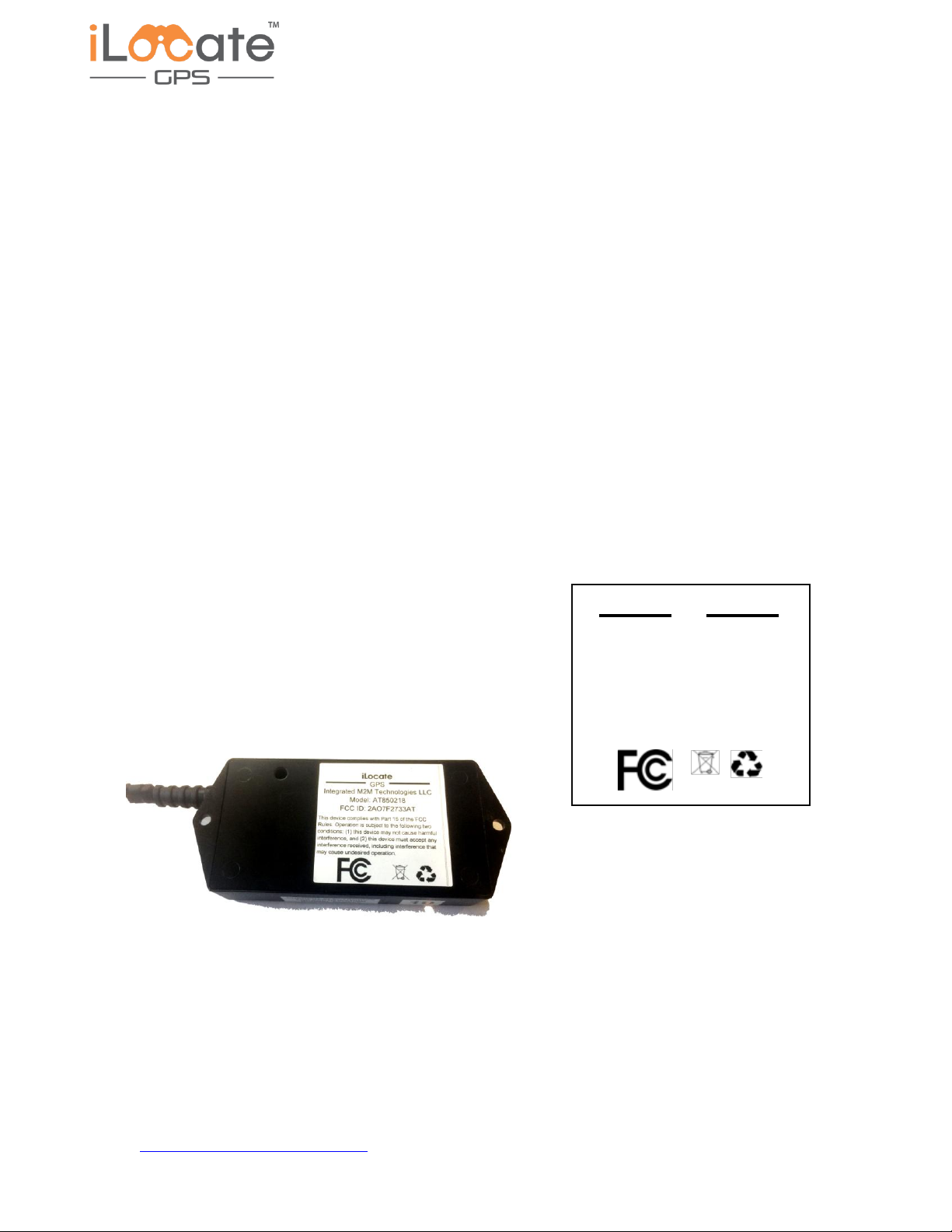
Label drawing - see here
Label Location - see below
This device complies with Part 15 of the FCC
Rules. Operation is subject to the following two
conditions: (1) this device may not cause harmful
interference, and (2) this device must accept any
interference received, including interference that
may cause undesired operation.
iLocate
GPS
Integrated M2M Technologies LLC
Model: AT850218
FCC ID: 2AO7F2733AT
This device complies with Part 15 of the FCC
Rules. Operation is subject to the following two
conditions: (1) this device may not cause harmful
interference, and (2) this device must accept any
interference received, including interference that
may cause undesired operation.
Table of contents
Popular GPS manuals by other brands

Voxson
Voxson Voxtrack GPS850 quick start guide

DeLorme
DeLorme GPS2058 user manual

Garmin
Garmin Group Ride instructions

Shenzhen v-sun Electronics
Shenzhen v-sun Electronics TLT-8A instruction manual

Sony
Sony NV-U74T - 4.3" Portable Navigation System instruction manual

TestTree
TestTree RF-Catcher instructions


Stars Navigation Technologies
Stars Navigation Technologies BT1.5 user manual

Brickhouse Security
Brickhouse Security Trackport 4 quick start guide

Baracoda
Baracoda GPS Receiver user manual

LXNAV
LXNAV LX90xx System installation manual

Midland
Midland ALAN MAP 600 user manual

ACR Electronics
ACR Electronics AIS Link MOB user manual