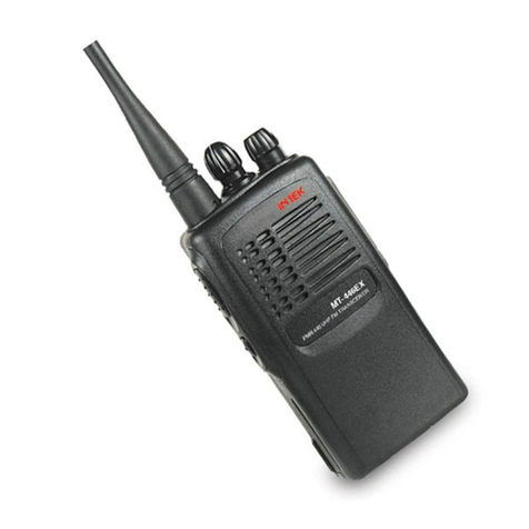
Intek MT-2020 User manual

Model No: INTEK
M
MT
T
-
-2
20
02
20
0/
/4
40
04
40
0
PMR 8 Channel – LPD 69Channel
Service Manual
Created by: Approved by: Rev. No:
For Stage : Release Date : Page 1 of 49

Model No: Drawing No:
Table of Contents
Pages
Specifications 3
Block Diagram 4
Schematic Diagram 5~6
Channel Frequency Charts 7~8
Printed Circuit Board 9~12
Test and Alignment Procedure 13~17
Parts List 18~37
Semiconductor Voltage Chart 38~40
Semiconductor Lead Assignment and Block Diagram 41~45
Exploded View and Parts List 46~49
Created by: Approved by: Rev. No:
For Stage : Release Date : Page 2 of 49

:
Title: MT2020/4040D SERVICE MANUAL
Rev. Date: January 5, 2005
SPECIFICATIONS
STANDARD TEST CONDITIONS
Supply Voltage - Battery 6.0Vdc
Antenna Impedance 50 Ohm
Audio Frequency 1 KHz
Main Signal Input 1mV
Deviation PMR AF 1 KHz / 1.5 KHz Dev
LPD AF 1 KHz / 3.0 KHz Dev
Audio Output Power ~1.8Vrms
Audio Output Impedance 8 ohms, non-inductive
Test Temperature 25 •
GENERAL SPECIFICATIONS
Transmitter CPU Controlled PLL Synthesizer
Receiver CPU Controlled double conversion, super-heterodyne
system
Intermediate Frequency 1st 21.4 MHz
2nd 450 KHz
Operating Frequencies PMR 446.00625MHz ~ 446.09375 MHz
LPD 433.07500 MHz ~ 433.77500 MHz
Frequency Stability 0.0005%
Battery Life 30 hours (typical)
Battery 4pcs AAA size Alkaline Battery or 4.8Vdc Ni-MH Battery
Pack
Transmitter/Receiver Switching Electrical
Ambient Conditions, Temperature / Humidity -15!c ~ 55!C / 40% ~ 70%
RECEIVER SPECIFICATIONS
Sensitivity <-120 @12dB SINAD
Audio Output ~2Vrms (w/o load)
Frequency Response 300 Hz ~ 2500 Hz
Image Rejection 54dB
Adjacent Channel Rejection 60dB
Inter Modulation Distortion 60dB
Conducted Rx Spurious -54dB
TRANSMITTER SPECIFICATIONS
Output Power(Conducted) PMR Band 500Mw (MT-2020) / 1W,500mW (MT-4040D)
LPD Band 10mW
Max. Deviation PMR "2.5 KHz(MAX)
LPD "5.0 KHz(MAX)
Frequency Error 5ppm(-15~+55!)
Current Drain <500 mA
Spurious Emission(Conducted) 50dB
Antenna Impedance 50 Ohm
Created by: Approved by: Rev. No:
For Stage : Release Date : Page 3 of 49

Model No:
For Stage : Release Date : Page 4 of 49
r.
BLOCK DIAGRAM
Created by: Approved by: Rev. No:

MT-2020D SCHEMATIC
DIAGRAM
PAGE 5 OF 49

MT-4040D SCHEMATIC
DIAGRAM
PAGE 6 OF 49

Model No: Drawing No:
CHANNEL FREQUENCY CHARTS
PMR Frequency Chart
Channel Frequency (MHz) Channel Frequency (MHz)
1 446.00625Mhz 2 446.01875Mhz
3 446.03125Mhz 4 446.04375Mhz
5 446.05625Mhz 6 446.06875Mhz
7 446.08125Mhz 8 446.09375Mhz
CTCSS Tone Frequency Chart
NO FREQ.(Hz) NO FREQ. (Hz) NO FREQ. (Hz)
1 67.0 14 107.2 27 167.9
2 71.9 15 110.9 28 186.2
3 74.4 16 114.8 29 179.9
4 77.0 17 118.8 30 186.2
5 79.7 18 123.0 31 192.8
6 82.5 19 127.3 32 203.5
7 85.4 20 131.8 33 210.7
8 88.5 21 136.5 34 218.1
9 91.5 22 141.3 35 225.7
10 94.8 23 146.2 36 233.6
11 97.4 24 151.4 37 241.8
12 100.0 25 156.7 38 250.3
13 103.5 26 162.2
Created by: Approved by: Rev. No:
For Stage : Release Date : Page 7 of 49

Model No: Drawing No:
LPD Frequency Chart
Channel Frequency (MHz) Channel Frequency (MHz)
01 433.07500 36 433.95000
02 433.1 0 00 0 37 4 33 . 97 5 00
03 43 3 .1 2 50 0 38 4 34 . 00 0 00
04 43 3 .1 5 00 0 39 4 34 . 02 5 00
05 43 3 .1 7 50 0 40 4 34 . 05 0 00
06 43 3 .2 0 00 0 41 4 34 . 07 5 00
07 43 3 .2 2 50 0 42 4 34 . 10 0 00
08 43 3 .2 5 00 0 43 4 34 . 12 5 00
09 43 3 .2 7 50 0 44 4 34 . 15 0 00
10 43 3 .3 0 00 0 45 4 34 . 17 5 00
11 43 3 .3 2 50 0 46 4 34 . 20 0 00
12 43 3 .3 5 00 0 47 4 34 . 22 5 00
13 43 3 .3 7 50 0 48 4 34 . 25 0 00
14 43 3 .4 0 00 0 49 4 34 . 27 5 00
15 43 3 .4 2 50 0 50 4 34 . 30 0 00
16 43 3 .4 5 00 0 51 4 34 . 32 5 00
17 43 3 .4 7 50 0 52 4 34 . 35 0 00
18 43 3 .5 0 00 0 53 4 34 . 37 5 00
19 43 3 .5 2 50 0 54 4 34 . 40 0 00
20 43 3 .5 5 00 0 55 4 34 . 42 5 00
21 43 3 .5 7 50 0 56 4 34 . 45 0 00
22 43 3 .6 0 00 0 57 4 34 . 47 5 00
23 43 3 .6 2 50 0 58 4 34 . 50 0 00
24 43 3 .6 5 00 0 59 4 34 . 52 5 00
25 43 3 .6 7 50 0 60 4 34 . 55 0 00
26 43 3 .7 0 00 0 61 4 34 . 57 5 00
27 43 3 .7 2 50 0 62 4 34 . 60 0 00
28 43 3 .7 5 00 0 63 4 34 . 62 5 00
29 43 3 .7 7 50 0 64 4 34 . 65 0 00
30 43 3 .8 0 00 0 65 4 34 . 67 5 00
31 43 3 .8 2 50 0 66 4 34 . 70 0 00
32 43 3 .8 5 00 0 67 4 34 . 72 5 00
33 43 3 .8 7 50 0 68 4 34 . 75 0 00
34 43 3 .9 0 00 0 69 4 34 . 77 5 00
35 43 3 .9 2 50 0
Created by: Approved by: Rev. No:
For Stage : Release Date : Page 8 of 49
MT-2020D TOP PCB MAP
PAGE 9 OF 49

MT-2020D BOTTOM PCB MAP
PAGE 10 OF 49

MT-4040D TOP PCB MAP
PAGE 11 OF 49

MT-4040D BOTTOM PCB MAP
PAGE 12 OF 49

Model No: Drawing No:
TEST AND ALIGNMENT PROCEDURE
1. RECOMMENDED TEST EQUIPMENT
1.1 HP8920A,B Radio Communication Tester or equivalent
1.2 Fluke 187 Digital Voltmeter or equivalent
1.3 HPE3615A Power Supply or equivalent
2. TEST PREPARATION
2.1 Connect a 6.0Vdc power supply to the positive battery terminal input point and the negative battery
terminal input point (GND) into the negative terminal.
2.3 Connect the HP8920A,B RF Output port to the ANT point.
2.4 TP12 should be connected to the Audio In Hi and TP10 should be connected to the Audio In Lo of the
HP8920B.
2.5 Set the unit at Ch1 (446.00625MHz)
3. CRYSTAL SELECT
3.1 X202 crystal is marked with red, blue, and no color marking. Matching capacitors C223, C223A, and
C223B that are in PCB will be determined by the markings and are as follows:
C223B
C223A
C223
Crystal C223A C223B
A Red Connect Connect
B NO COLOR Connect NC
C Blue NC NC
4. VCO ADJUSTMENT
4.1 Set the unit at PMR Ch1 (446.00625MHz) and connect a digital voltmeter to TP1 (VCO PD).
4.2 Press the PTT Button so the unit is in transmit mode.
4.3 Adjust L303 until the voltmeter reads around 3.1~3.2Vdc (without VCO Plate). L303 is located
under the shieldcan.
Solder VCO Plate and let temperature stabilize. Recheck TX VCO at Ch1, should be 2.8~3.1Vdc
4.4 Release the PTT switch so the unit will be in Receive mode.
4.5 Observe the voltage at TP1, the voltage should be 2.5~3.2Vdc.
4.6 Set the unit at PMR Ch8 (446.09375MHz).
4.7 Press the PTT switch so the unit is in transmit mode.
4.8 Observe the voltage at TP1, the voltage should be 2.8~3.2Vdc.
4.9 Release the PTT switch so the unit will be in receive mode.
4.10 Observe the voltage at TP1, the voltage should be 2.5~3.2Vdc.
4.11 Set the unit at LPD Ch1 (433.075MHz)
4.12 Press the PTT switch so the unit is in transmit mode.
4.13 Observe the voltage at TP1, the voltage should be 1.0 ~ 1.8Vdc.
4.14 Release the PTT switch so the unit will be in receive mode.
4.15 Observe the voltage at TP1, the voltage should be 0.9 ~ 1.7Vdc.
NOTE : Above Specifications are measured with VCO Plate soldered.
Created by: Approved by: Rev. No:
For Stage : Release Date : Page 13 of 49

Model No: Drawing No:
5. TRANSMITTER FREQUENCY ALIGNMENT
Equipment Setting:
Filter : 50Hz~15kHz
IF Filter : PMR 15kHz; LPD : 230kHz
De-Emphasis : OFF
Monitor : Pk-Pk/2
Input : 200mVrms; 1kHz Deviation
5.1 Set the unit/equipment for TX Test (SEE FIGURE 2). Set the unit at PMR Ch1. Press the PTT button so
the unit will be in transmit mode.
5.2 Adjust CT201 trimmer capacitor until such that the output frequency is equal to the channel frequency
with maximum error of +/-200Hz (OQA Limit of +/-800Hz).
Production will control as follows:
- PCBA Alignment : +/-200Hz
- Casing Test : +/-500Hz
- OQA Limit : +/-800Hz
6. TRANSMITTER OUTPUT POWER CHECK
MT2020D
6.1 Set the unit at PMR Ch1. (use short cable)
6.2 Press the PTT button so the unit is in transmit mode.
6.3 Transmit Power should be between 0.4~1.0W.
6.4 Set the unit at LPD Ch1.
6.5 Press the PTT button so the unit is in transmit mode. Ensure the TX Power is 10~70mW.
MT4040D
6.6 Set the Power Supply to 5Vdc. Set the unit at PMR Ch1. (use short cable)
6.7 Press the PTT button so the unit is in transmit mode. Make sure Power Supply is 5Vdc during PTT.
6.8 Transmit Power should be between 1.4~2.5W.
6.9 Solder J3. Press the PTT button so the unit is in transmit mode. Transmit Power should be between
0.4~1.0W.
6.10 Set the unit at LPD Ch1.
6.11 Press the PTT button so the unit is in transmit mode. Ensure the TX Power is 8~70mW
7. TRANSMITTER DEVIATION ADJUSTMENT
7.1 Set the unit at PMR Ch1. Connect an audio generator (600ohms) to the microphone terminal pads. The
audio frequency should be set at 1kHz with a level of 200mVrms.
7.2 Connect an FM Deviation Meter (on the HP8920B) on ANT point. Set the monitor to read (Pk to Pk)/2
deviation. Set Filter 1 to 50Hz and Filter 2 to 15kHz. De-emphasis should be set to Off.
7.3 Press the PTT button so the unit will be in transmit mode.
7.4 Adjust RV2 and observe the reading at the Deviation Meter, the reading should be between 1.5 to
1.8kHz (MT2020D) /between 1.8 to 2.1kHz (MT4040D).
7.5 Set the unit to LPD Ch1. Set the monitor to read (Pk to Pk)/2 deviation. Set Filter 1 to 50Hz and Filter 2
to 15kHz. De-emphasis should be set to Off. Set the IF Filter to 230kHz. Press the PTT button and
check the Deviation Meter, the reading should be 2.8 ~ 5.0kHz.
7.6 At PMR Ch1, decrease the audio generator level until the deviation reads +/-1.2 kHz. The generator level
should be between 3~10mV
. 7.7 Check that the transmit audio distortion is less than 5%. TX Distortion should be checked at 1.2kHz
Modulation, using Narrowband Filter with De-Emphasis ON.
7.8 Set the CTCSS to Code 1. Turn OFF the audio generator. Press the PTT button so the unit will be in
transmit mode.
7.9 Confirm that the CTCSS Code modulation is between 0.4 to 0.7kHz
7.10 Set the CTCSS to Code 38. Press the PTT button so the unit will be in transmit mode.
7.11 Confirm that the CTCSS Code modulation is between 0.4 to 0.7kHz.
Created by: Approved by: Rev. No:
For Stage : Release Date : Page 14 of 49

8. RECEIVER ALIGNMENT
8.1 Set the unit/equipment for RX Test (SEE FIGURE 3). Set the RF Generator level to –47dBm. The
generator should be set for 1.5kHz deviation at 1kHz modulation. Set the Impedance at 8ohms.
8.2 Set Filter 1 to 25Hz and Filter 2 to 15kHz.
8.3 Set the unit at PMR Ch1. Set the Volume level for 4 (default Level ). Align CF2 for maximum level.
Check the audio level, should be 0.27~0.6Vrms
8.4 Confirm that the RX Distortion is less than 5%.
8.5 Reduce the RF Generator signal level until a 12dB Sinad reading is achieved. The RF Generator level
should be less than –120dBm.
8.6 Set the RF Generator level to –47dBm, and set the unit Volume Level to maximum.
8.7 Check the maximum Audio Output Level, should be >1.70Vrms.
8.8 Set the unit at LPD Channel 1.
8.9 Set the RF generator at 3.0kHz deviation at 1kHz modulation.
8.10 Repeat Procedure 8.5 and confirm that the RF Generator is less than –122dBm at 12dB SINAD.
9. SQUELCH THRESHOLD AND HYSTERISIS
9.1 Set unit same as 8.1.
9.2 Set the RF Generator level until unit is at 2dB Sinad or unit is squelched (RX Off).
9.3 Slowly increase the RF Signal Generator level until the unit un-squelches (RX On), confirm that the
sensitivity is between 6~14dB SINAD (PMR Band).
10. VOX TEST
10.1 Set the unit into VOX Mode (Level 2). The VOX icon should be displayed on the LCD.
10.2 Connect an audio generator into the microphone terminal. The audio frequency should be set for 1kHz
frequency with a level of 0mVrms and the output should be turned off.
10.3 Turn on the output of the audio generator.
10.4 Increase the Audio Generator level until unit goes into TX Mode.
10.5 Check the Generator level, it should be between 0.8 ~ 2.0mV.
11. LOW BATTERY LEVEL TEST
11.1 Set the unit into standby mode.
11.2 Set the Power Supply voltage to 4.8Vdc.
11.3 Slowly decrease the Power Supply Voltage until the Battery icon appears and blink.
11.4 Observe the Power Supply Level. The level must be between 4.1 to 4.4Vdc
Created by: Approved by: Rev. No:
For Stage : Release Date : Page 15 of 49

Model No: Drawing No:
FIGURE 1 (VCO TEST)
FIGURE 2 (TX TEST)
Created by: Approved by: Rev. No:
For Stage : Release Date : Page 16 of 49

Model No: Drawing No:
FIGURE 3 (RX TEST)
Created by: Approved by: Rev. No:
For Stage : Release Date : Page 17 of 49

Model No: Drawing No:
MT-2020 PARTS LIST
C1 100P Capacitor Chip NP0 0402 1
C10 100P Capacitor Chip NP0 0402 1
C100 0.1(X7R) Capacitor Chip X7R 0603 1
C101 0.1 Capacitor Chip Y5V 0402 1
C102 0.1 Capacitor Chip Y5V 0402 1
C103 100P Capacitor Chip NP0 0402 1
C104 100P Capacitor Chip NP0 0402 1
C105 100P Capacitor Chip NP0 0402 1
C106 10UF(3X5) Capacitor Elect. 3X5 1
C107 0.1 Capacitor Chip Y5V 0402 1
C108 820P(X7R) Capacitor Chip X7R 0402 1
C109 0.0022 Capacitor Chip X7R 0402 1
C11 0.0082 Capacitor Chip X7R 0402 1
C110 0.022 Capacitor Chip X7R 0402 1
C111 0.0022 Capacitor Chip X7R 0402 1
C112 0.022 Capacitor Chip X7R 0402 1
C113 0.1 Capacitor Chip Y5V 0402 1
C115 3P Capacitor Chip NP0 0402 1
C116 100P(03) Capacitor Ceramic 0603 NP0 1
C117 0.1 Capacitor Chip Y5V 0402 1
C118 100P Capacitor Chip NP0 0402 1
C119 100P Capacitor Chip NP0 0402 1
C12 1UF Capacitor Chip Y5V 0603 1
C120 100P Capacitor Chip NP0 0402 1
C121 100P Capacitor Chip NP0 0402 1
C122 1P Capacitor Chip NP0 0402 1
C123 100P Capacitor Chip NP0 0402 1
C125 0.001 Capacitor Chip X7R 0402 1
C126 100P Capacitor Chip NP0 0402 1
C127 10UF(3X5) Capacitor Elect. 3X5 1
C128 10P Capacitor Chip NP0 0402 1
C129 100/6.3(5X7) Capacitor Elect 1
C13 0.01 Capacitor Chip X7R 0402 1
C130 0.039 Capacitor Chip X7R 0402 1
C131 47uF/6.3(4X7) Capacitor Elect 1
C132 100P Capacitor Chip NP0 0402 1
C133 10UF(3X5) Capacitor Elect. 3X5 1
C134 0.1 Capacitor Chip Y5V 0402 1
C135 0.1 Capacitor Chip Y5V 0402 1
Created by: Approved by: Rev. No:
For Stage : Release Date : Page 18 of 49
Model No: Drawing No:
C136 100P Capacitor Chip NP0 0402 1
C137 100P Capacitor Chip NP0 0402 1
C138 0.0027 Capacitor Chip X7R 0402 1
C139 47P Capacitor Chip NP0 0402 1
C14 1P Capacitor Chip NP0 0402 1
C140 100P Capacitor Chip NP0 0402 1
C141 100P Capacitor Chip NP0 0402 1
C142 100P Capacitor Chip NP0 0402 1
C143 100P Capacitor Chip NP0 0402 1
C144 10UF(3X5) Capacitor Elect. 3X5 1
C15 2P(03) Capacitor Ceramic 0603 NP0 1
C16 220P Capacitor Chip X7R 0402 1
C162 100P Capacitor Chip NP0 0402 1
C17 2P(03) Capacitor Ceramic 0603 NP0 1
C171 0.1 Capacitor Chip Y5V 0402 1
C18 7P Capacitor Chip NP0 0402 1
C19 100P Capacitor Chip NP0 0402 1
C2 33P(03) Capacitor Ceramic 0603 NP0 1
C20 1P Capacitor Chip NP0 0402 1
C207 100P Capacitor Chip NP0 0402 1
C208 33P Capacitor Chip NP0 0402 1
C209 33P Capacitor Chip NP0 0402 1
C21 10P Capacitor Chip NP0 0402 1
C211 0.1 Capacitor Chip Y5V 0402 1
C213 100P Capacitor Chip NP0 0402 1
C218 5P Capacitor Chip NP0 0402 1
C219 100P Capacitor Chip NP0 0402 1
C22 100P Capacitor Chip NP0 0402 1
C221 100P Capacitor Chip NP0 0402 1
C222 68P Capacitor Chip NP0 0402 1
C223 22P Capacitor Chip NP0 0402 1
C223A 3P Capacitor Chip NP0 0402 1
C223B 3P Capacitor Chip NP0 0402 1
C224 22P Capacitor Chip NP0 0402 1
C224A 8P Capacitor Chip NP0 0402 1
C23 100P Capacitor Chip NP0 0402 1
C24 0.1 Capacitor Chip Y5V 0402 1
C25 100P Capacitor Chip NP0 0402 1
C26 100P Capacitor Chip NP0 0402 1
C27 0.01 Capacitor Chip X7R 0402 1
C28 100P Capacitor Chip NP0 0402 1
Created by: Approved by: Rev. No:
For Stage : Release Date : Page 19 of 49
Model No: Drawing No:
C29 220P(X7R) Capacitor Chip X7R 0402 1
C3 0.1 Capacitor Chip Y5V 0402 1
C30 3P(03) Capacitor Ceramic 0603 NP0 1
C301 0.1 Capacitor Chip Y5V 0402 1
C302 22P Capacitor Chip NP0 0402 1
C303 4P Capacitor Chip NP0 0402 1
C304 3P Capacitor Chip NP0 0402 1
C305 220P Capacitor Chip NPO 0402 1
C306 5P Capacitor Chip NP0 0402 1
C307 3P Capacitor Chip NP0 0402 1
C308 470P Capacitor Chip X7R 0402 1
C309 18P Capacitor Chip NP0 0402 1
C31 220P(X7R) Capacitor Chip X7R 0402 1
C311 12P Capacitor Chip NP0 0402 1
C312 9P Capacitor Chip NP0 0402 1
C314 0.039 Capacitor Chip X7R 0402 1
C315 1UF Capacitor Chip Y5V 0603 1
C316 0.033 Capacitor Chip Y5V 0402 1
C32 0.1(X7R) Capacitor Chip X7R 0603 1
C33 0.1 Capacitor Chip Y5V 0402 1
C34 0.1 Capacitor Chip Y5V 0402 1
C35 100P Capacitor Chip NP0 0402 1
C36 0.33 Capacitor Chip Y5V 0603 1
C37 6P Capacitor Chip NP0 0402 1
C38 100P Capacitor Chip NP0 0402 1
C39 100P Capacitor Chip NP0 0402 1
C3A 4P(03) Capacitor Ceramic 0603 NP0 1
C4 4P Capacitor Chip NP0 0402 1
C40 100P Capacitor Chip NP0 0402 1
C41 15P Capacitor Chip NP0 0402 1
C42 100P Capacitor Chip NP0 0402 1
C43 100P Capacitor Chip NP0 0402 1
C44 15P Capacitor Chip NP0 0402 1
C45 7P Capacitor Chip NP0 0402 1
C46 100P Capacitor Chip NP0 0402 1
C47 0.1 Capacitor Chip Y5V 0402 1
C48 0.047 Capacitor Chip X7R 0402 1
C49 100P Capacitor Chip NP0 0402 1
C5 0.056 Capacitor Chip X7R 0402 1
C50 0.01 Capacitor Chip X7R 0402 1
C501 100P Capacitor Chip NP0 0402 1
Created by: Approved by: Rev. No:
For Stage : Release Date : Page 20 of 49
This manual suits for next models
1
Table of contents
Other Intek Two-way Radio manuals

Intek
Intek ET Series User manual

Intek
Intek MT-446EX User manual

Intek
Intek KT-900EE User manual

Intek
Intek HX-446S User manual

Intek
Intek MT-174XPS User manual

Intek
Intek H-520 PLUS User manual

Intek
Intek MT-465N User manual

Intek
Intek DX-174S User manual

Intek
Intek DX-174S Operating and maintenance manual

Intek
Intek i-Talk T90 User manual