IntelliCam CNS-4G User manual

DocRef#0540601
CNS-4G SMS TEXT - User Guide Revised 2021-12-28
CNS-4G
SMS Cellular Notification System
DocRef#0460601
CNS-4G - User Guide Page 1
Table of Contents
Table of Contents:
Features
Page 2
Chapter 1
Hardware
Page 3
Chapter 2
Overview
Page 4
Chapter 3
Gateway LED Indicators
Page 5
Chapter 4
RX Receiver LED Indicators
Page 6
Chapter 5
Gateway Programming & Configuration
Page 7
Chapter 6
Setting up the SIM Card
Page 8
Chapter 7
SMS Notification Testing
Page 9
Chapter 8
Phone Numbers and Messaging
Page 10-11
Appendix A
Technical Specifications
Page 12
Appendix B
List of common APN Numbers
Page 13
Appendix C
Contact Information
Page 13
DocRef#0460601
CNS-4G - User Guide Page 2
Features
Features:
●Weatherproof Ruggedized Pelican Case Enclosure
●AT&T 4G/3G or Verizon LTE and other providers
●Texting of “Customized”Alarm Messages and Sensor ID #s
●Text up to six different numbers simultaneously
●Integrated 8 “C” Cell Battery Pack
●Two IR-904 Passive Infrared Sensors with Hard ID’s and tree clips
●Up to 30 days of standby time (10 triggers per day)
DocRef#0460601
CNS-4G - User Guide Page 3
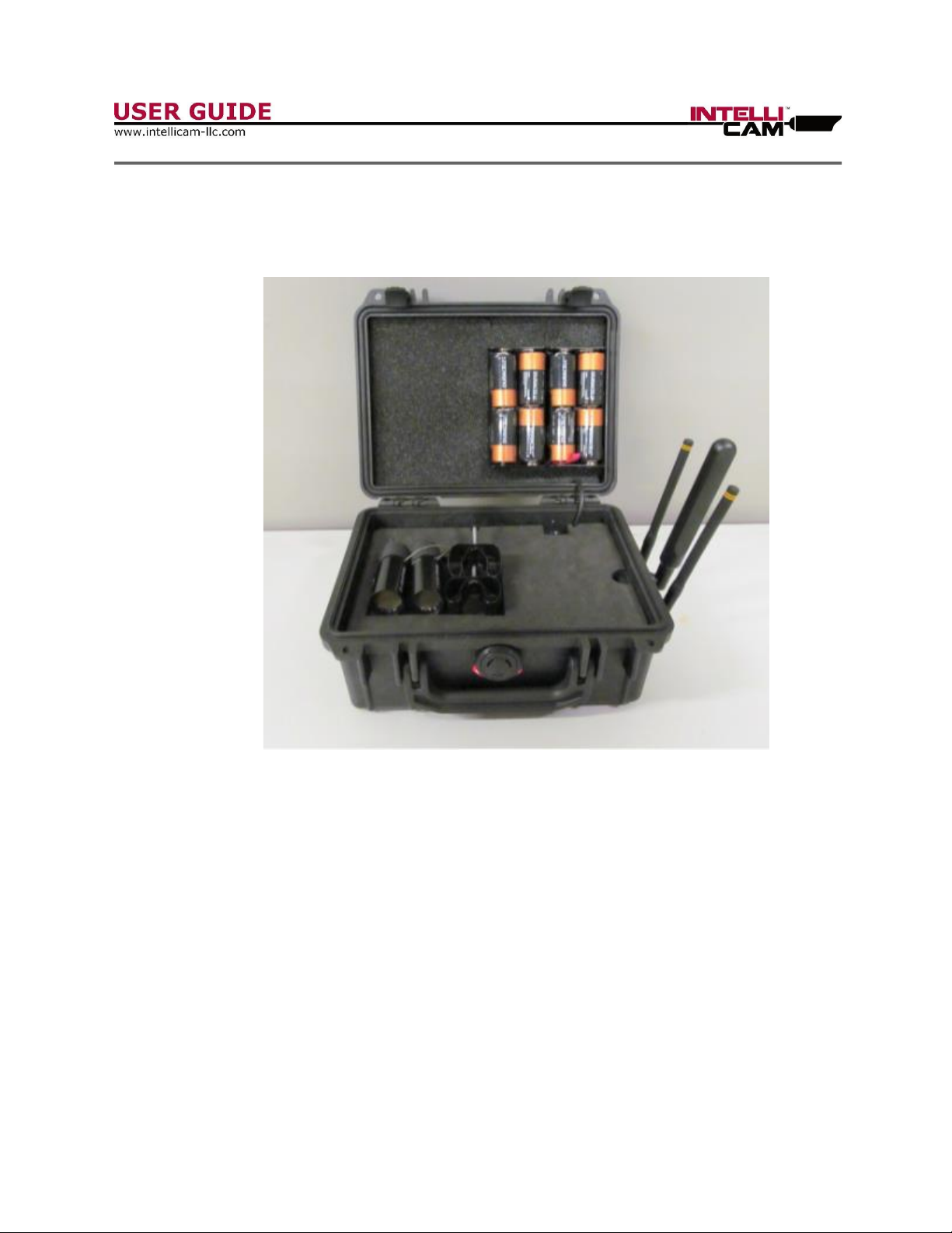
Chapter 1 - Hardware
Check this list before using.
Contact Intellicam if you find any missing items.
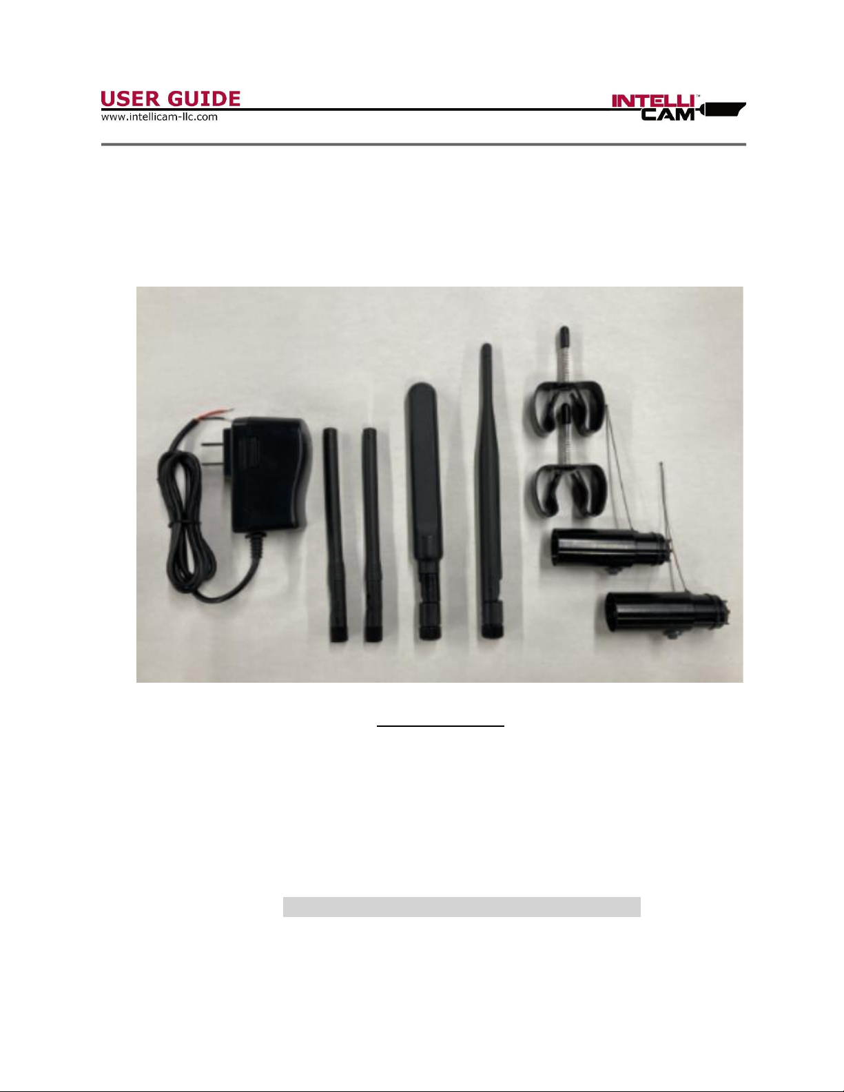
Accessory List:
1. AC Power Adapter (QTY 1) –Recommended when programming the Gateway.
2. Sensor Antenna (QTY 2) –Antennas used to receive sensor alarm signals.
3. Cellular Antenna (QTY 1) –Cellular antenna for Gateway to send SMS messages
4. Wi-Fi Antenna (QTY 1) –Used only when programming the Gateway
5. Tree Clip (QTY 2) –Used when deploying sensors in the field
6. Sensors (QTY 2) –Hard ID 1 and Hard ID 2 used to trigger Gateway
Warning: Do not overtighten antennas!

DocRef#0460601
CNS-4G - User Guide Page 4
Chapter 2 –Overview
The CNS-4G Cellular Notification System has been designed as an early warning or
situational awareness device. The Gateway can be triggered by any of our Intellicam
Sensors as long as the ID is ID-1 or ID-2. You can program any Intellicam sensor for
ID-1 or ID-2. The CNS-4G comes standard with 2 each IR-904 Passive Infrared Sensors
that are pre-programmed with a “Hard” ID-1 and “Hard” ID-2. The Gateway can be
triggered by an unlimited number and type of sensor as long as they are an ID-1 or an
ID-2.
Once you have established your perimeter using one or more of our Intellicam sensors,
check to see if you are within communication range (covered in Chapter 4). Make sure
that you are receiving a good cellular signal (covered in Chapter 3). Now that you have
established all the necessary communications, your system is now ready to start sending
the pre-programmed SMS text messages to the appropriate recipient’s cell numbers. Up
to six different cellular numbers can be programmed in to the Gateway for simultaneous
notifications.
Depending on the location and cellular coverage, it can take anywhere from 30 seconds
to two minutes for the CNS-4G to connect to a cell tower and transmit the SMS
message. During heavy traffic times it can take longer, but the advantage of using SMS
text messaging is, the message will go through.
SIM/UIM Card Installation
The CNS-4G supports normal SIM/UIM only, so if you’re using a Micro SIM or Nano SIM
card, you may need to use a Micro SIM or Nano SIM to Normal SIM adapter. Make sure
your Gateway is powered off, then use a needle-like object (such as a paper clip) to
push the button near the SIM/UIM card holder, it will eject out immediately. Insert the
SIM/UIM card into the card holder and insert the SIM and card holder into Gateway and
make sure it is seated securely. If the SIM/UIM card is not properly inserted, the “Alarm
LED will illuminate on the Gateway.
Warning: Never install SIM/UIM card when the Gateway is powered on!
Warning: Be sure the antennas are connected and the SIM card is installed,
before installing the batteries or connecting to external power!

DocRef#0460601
CNS-4G - User Guide Page 5
. This is accomplished by the PHOTOCELL . Access to the
Chapter 3 –Gateway LED Indicators:
Indicator
Status
Condition
Power (PWR)
On
Powered On
Off
Powered Off
1 Light
Cellular signal is weak
Signal Strength
2 Lights
Cellular signal is medium
3 Lights
Cellular is strong
System (SYS)
Blinking
Gateway is working correctly
Off
Gateway is not working
Online
On
Gateway has access to the internet
Off
Gateway has no internet access
Alarm
On
* SIM/UIM Card is not inserted correctly or
broken
* Antenna signal too weak
1 Blink per Second
Cellular module was not registered to gateway
2 Blinks per Second
Gateway cannot access cellular system
Off
No Alarms (This is good)
Wifi
On
Wifi On and enabled
Off
WIFI Disabled or not working

DocRef#0460601
CNS-4G - User Guide Page 6
Chapter 4 –RX Receiver LED Indicators
1. Upon power up you will see 3 RED LED’s on the RX Receivers illuminate as in Figure
1. The LED’s will only stay fully lit for about 2 seconds. You may see the RED LED’s
flash periodically for the first 5 minutes while the receivers are in Range Test mode.
When you power up the Gateway and a sensor at the same time, they will communicate
with each other to help set up your perimeter. You know that you are within sensor
range when the Receiver’s RED LED’s continue to blink.
2. If you trigger the CNS-4G with Sensor ID-2 while the receivers are still in Range Test
mode. The LED’s will look like figure 2. The two GREEN LED’s indicate Sensor ID-2. If
you use Sensor ID-1, two BLUE LED’s will light up.
3. Figure 3 shows what the GREEN LED’s will look like if you trigger the CNS-4G with
Sensor ID-2, after the range test mode is over and the receivers are standby mode.
Figure 1. Figure 2. Figure 3.
DocRef#0460601
CNS-4G - User Guide Page 7
Chapter 5 –Programming & Configuration
All programming and configuration should be performed at your office, before deploying
in the field.
During configuration you should use the AC Adapter plug to power the Gateway, rather
than using battery power which might shorten the battery life of your CNS-4G.
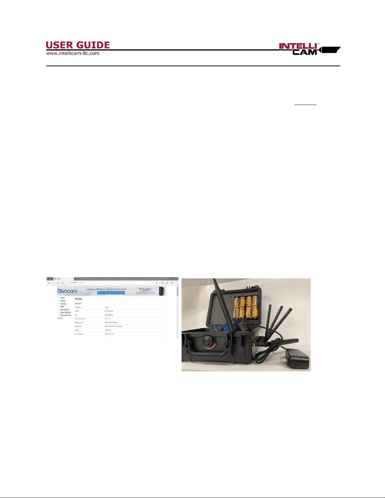
Power up the Gateway (use AC Adapter and Wi-Fi Antenna Figure 6). Leave all other
cables plugged in. Connect your laptop or Wi-Fi enabled phone to the Gateway’s Wi-Fi
hotspot named “Bivocom_****”. The password to the “Bivocom” Wi-Fi hotspot is
“admin123”. Next, open your browser and enter the IP Address to 192.168.1.1. Once
the configuration page has opened, enter the User Name of “admin” and the Password is
“admin”. The configuration page will look like Figure 5.
Option: You may also connect through an Ethernet cable by configuring your local IP to
192.168.1.100, then opening your browser to 192.168.1.1. If you use this option, it is
highly recommended that you change the logon password from “admin” immediately.
Figure 5 Figure 6
DocRef#0460601
CNS-4G - User Guide Page 8
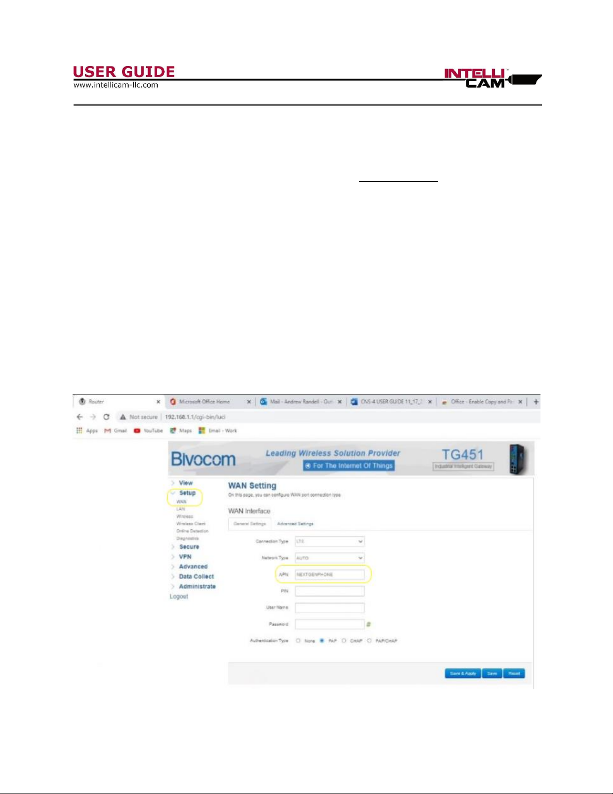
Chapter 6 –Setting Up the SIM CARD with the Gateway
Warning: Make sure that you have your SIM’s APN Number from your provider.
1. Prior to this step make sure an appropriate SIM/UIM card is installed in the
Gateway. Instructions for SIM/UIM card installation are covered on page 4.
2. In the Menu tab on the left, click on Setup, then WAN, and enter your APN
Number. In the example below the APN Number is “NXTGENPHONE”. (Fig. 7)
Refer to appendix B for a list of common APN Numbers by carrier.
3. Now click on “Save & Apply”. Once you have completed this step the Gateway is
ready for “Text Testing”. Once you have completed a Text Test you can move on
to entering desired “cell numbers” to receive the SMS alarm texts and what
“customized” messages you want to send with Sensor ID-1 and with Sensor ID-2
Figure 7
DocRef#0460601
CNS-4G - User Guide Page 9
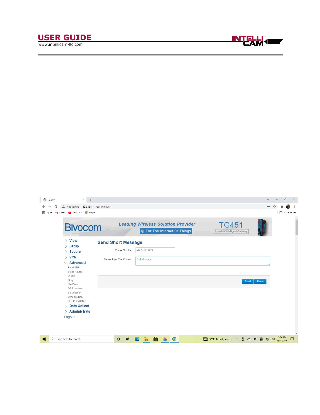
Chapter 7 –SMS Notification Testing
Test the SMS Notification System:
1. Make sure that your Gateway is powered ‘on’ and you are connected to the
Gateway via Wi-Fi or cable and your Gateway “System” LED is blinking.
2. In the Menu on the left, click on “Advanced”, then “Send SMS”. Make sure you
put a “+” sign before the country code (1 in the US), then the area code and
phone number. Do not use any “dashes”. Example: +18047981004
3. Type in your text message and click on “Send”. Your text message should arrive
at your phone within a few seconds. If not please refer to the LED Indicator chart
to trouble shoot.
Figure 8

DocRef#0460601
CNS-4G - User Guide Page 10
Chapter 8 –Phone Numbers and Messaging
1. Make sure that your Gateway is powered ‘on’ and you are connected to the
Gateway via Wi-Fi or cable, and your Gateway is showing that it is “Online”.
2. In the Menu on the left, click on “Advanced”, then “DI DO”. Next enter your
phone number(s). Make sure you put a “+” sign before the country code (1 in the
US), then the area code and phone number. Do not use any “dashes”. Add a
comma between phone numbers, but no spaces.
Example Numbers: +18047981004,+18045469923
3. Once you have put in all the phone numbers and messages for your application,
click on the “Save and Apply” icon. (Fig. 9)
4. The Gateway is now fully programmed and ready for deployment.
Figure 9

DocRef#0460601
CNS-4G - User Guide Page 11
Chapter 8 –Field Deployment
Important: Ensure that CNS-4G and all Sensor batteries are at full strength!
Range Test Mode: After turning the CNS 4G “on”with the power switch, it will go into a
5 minute Range Test mode. The RX Receiver’s RED LED’s will go on for 2 seconds then
turn off. Next install the CR1225 batteries in the IR-904 Sensor. After the “booting up”,
the Sensor will go into a Range Test mode and transmit an outgoing signal to the CNS-
4G every couple of seconds. The LED’s on the sensor will blink, and the RED LED’s on
the RX Receiver will blink as they receive incoming signals from the sensor. This verifies
that the CNS-4G is within range and receiving signals from the sensor. If the distance
between the Sensors and CNS-4G exceed the RF transmission output from the Sensor,
the RED LED’s on the RX Receiver will become erratic or stop blinking. After this Range
Test period, the CNS-4G will automatically go into Alarm Mode and the Receiver’s Blue
LED’s and Green LED’swill only come on when the CNS-4G receives a sensor alarm
signal.
Important: Make sure to read the User Manual for the IR-904 Passive Infrared
Sensors.
The CNS-4G is designed to accept any number or type of sensors, but all sensors must
have an ID-1 or ID-2. The CNS-4G will not accept any other Sensor ID’s other ID-1 and
ID-2.
When a sensor sends an alarm with an ID-1 or ID-2, the CNS-4G will receive the alarm,
connect to the cell network and send the associated Alarm ID and customized SMS text
message. This usually takes about 45 seconds, but can take up to 2 minutes depending
on cell strength and traffic. Even in areas with poor cellular coverage, the SMS text
message will eventually go through. This is one of the advantages of using SMS text
messaging.

DocRef#0460601
CNS-4G - User Guide Page 12
Appendix A:
Technical Specifications
Technical Specifications:
Batteries
8 “C” Cells
External Power
12 V DC
Current
Sleep: Average 8 mA
Connected to Network: Average 350 mA
Operational Life
(Using 8 “C” Cells)
30 days with 10 triggers
per day.
Enclosure Rating
IP 67
Cellular Antenna
5.42 dBi Peak Gain
SIM Card
SIM / UIM Micro SIM only
Dimensions
9.50” x 7.75” x 4.25”
Weight
5.20 lbs.

DocRef#0460601
CNS-4G - User Guide Page 13
Appendix B: Common APN Numbers
Network
APN Number
AT&T Standard SIM Card (Business Plan)
NEXTGENPHONE
AT&T Static IP SIM Card (Business Plan)
psmtneofin
AT&T Standard SIM Card
broadband
AT&T Standard SIM Card (Business Plan)
i2gold
Bell
internet.com
inet.bell.ca
Fido
internet.fido.ca
ICE
icecellular
Rogers
lteinternet.apn
ltemobile.apn
internet.apn
vpn.com
Rogers Static IP SIM Card
staticip.apn
Sasktel
proxy.stm.sk.ca
inet,stm.sk.ca
T-Mobile 4G Non Static IP
fast.t-mobile.com
T-Mobile 3G Non Static IP
epc.t-mobile.com
T-Mobile Static IP
brb.t-mobile.com
Tracfone (Walmart)
wap.tracfone
Verizon (4G, LTE only, USA only)
vzwinternet
Verizon Static IP
NE01.VZWSTATIC
WE01.VZWSTATIC
SO01.VZWSTATIC
MW01.VZWSTATIC
Appendix C: Contact Information
Contact Information:
IntelliCam LLC
11138 Air Park Road, Suite H
Ashland, VA 23005
PH: 804-798-1004
www.intellicam-llc.com
Table of contents


