Intelligent Lighting Controls, Inc. Light Master User manual

INTELLIGENT LIGHTING CONTROLS, INC.
5229 Edina Industrial Boulevard
Minneapolis. Minnesota 55439
Phone 952 829 1900
FAX 952 829 1901
1-800-922-8004
USER GUIDE
Version 1C
9/20/00


Light Master User Manual
Version 1C 9/20/00
Structure
The major components making up the
controller are:
• enclosure
• control transformer
• CPU I/O board
• additional I/O boards
• programming module
• lighting relays
Enclosure –The enclosure is rated NEMA 1.
It is divided into a line voltage section con-
taining the line voltage side of the control
transformer and lighting relays and a low volt-
age section containing the Class 2 side of the
lighting relays, transformer secondaries and
electronic components. Enclosures are avail-
able in 6 sizes to accommodate 8, 16, 24, 32,
40 and 48 inputs, outputs, and lighting relays.
Transformer –A 40 VA multi-tap control trans-
former (120 or 277/24 VAC) provides the 24
VAC input to power the controller electronics.
CPU I/O Board –The CPU board provides
the controller’s intelligence and memory and
the first eight (8) of the controller inputs and
outputs. Major components include:
•Switch Inputs –can accept input from either
2- or 3-wire momentary or maintained dry
contact devices. Each input has two associ-
ated LEDs (light emitting diodes). The ON
LED lights when a closure is sensed between
the ON and COMMON terminals. The OFF
LED lights when a closure is sensed between
the OFF and COMMON terminals. The inputs
are noise- and surge-resistant. A switch may
be located up to 1500 feet from the con-
troller, provided you use a minimum of 18
gauge wire.
•Relay Outputs –Each output switches its asso-
ciated lighting relay ON and OFF. Each out-
put has an associated LED. The LED lights
when the output switches the relay ON.
•Override Switches –Each relay output is
equipped with an ON and an OFF override
switch. These switches allow you to turn the
associated lighting relay ON or OFF.
•Stagger Start –The controller switches those
relays impacted by the same switch signal
ON/OFF, one at a time.
Overview
The Light Master Programmable Contactor is a microprocessor-based programmable lighting
controller. You can program each of the controller inputs to control any or all of the relay out-
puts. The Light Master is UL and FCC approved for commercial and residential applications.

Section 1 Controller Description
1.0 Section Overview .......................................................................... 1-1
1.1 Controller Architecture ................................................................. 1-2
1.1.1 Enclosure................................................................................ 1-2
1.1.2 Transformer ............................................................................ 1-2
1.1.3 CPU I/O Board....................................................................... 1-3
1.1.4 Additional I/O Boards........................................................... 1-4
1.1.5 Programming Module .......................................................... 1-8
1.1.6 Lighting Relays....................................................................... 1-8
1.2 I/O Options ..................................................................................... 1-9
1.2.1 Telephone Add-On Module ................................................ 1-9
1.2.2 PC Add-On Module ............................................................. 1-9
Section 2 Installation
2.0 Section Overview .......................................................................... 2-1
2.1 Pre-Installation Checks .................................................................. 2-2
2.2 Mounting the Controller................................................................ 2-2
2.2.1 Location ................................................................................. 2-2
2.2.2 Environmental Considerations ............................................ 2-2
2.2.3 Distance From Control Devices .......................................... 2-2
2.3 Wiring the Controller...................................................................... 2-2
2.3.1 Wire the Control Transformer............................................... 2-2
2.3.2 Connect Line and Load ...................................................... 2-2
2.3.3 Wire Switch Inputs ................................................................. 2-2
2.3.4 Set Relay Response .............................................................. 2-2
2.4 Pre-Power Checks.......................................................................... 2-5
2.4.1 Check Controller Power Input............................................. 2-5
2.4.2 Verify Controller’s Supply Voltage....................................... 2-5
2.4.3 Double-Check Connections ............................................... 2-5
2.5 Power-Up and Check Out............................................................ 2-5
2.5.1 Power-Up the Controller ...................................................... 2-5
2.5.2 Verify the Lighting Relays ..................................................... 2-5
2.5.3 Perform Initial Programming Procedures........................... 2-5
2.5.4 Verify the Switching Function .............................................. 2-5
2.5.5 Verify the Timer Functions .................................................... 2-5
2.6 Troubleshooting.............................................................................. 2-6
2.6.1 Controller Will Not Power-Up ............................................... 2-6
2.6.2 Lighting Relay(s) Will Not Function...................................... 2-6
2.6.3 Switch Input Will Not Function............................................. 2-6
2.6.4 Timers Will Not Function Properly ........................................ 2-6
2.6.5 Entire I/O Board(s) Doesn’t Work ........................................ 2-6
Light Master User Manual
Version 1C 9/20/00
Table of Contents

Table of Contents
Light Master User Manual
Version 1C 9/20/00
Section 3 Programming
3.0 Section Overview .......................................................................... 3-1
3.1 Relay Status .................................................................................... 3-2
3.2 Controlling Relays From the Keypad........................................... 3-3
3.3 Relay Output .................................................................................. 3-4
3.4 Set Relay Parameters .................................................................... 3-5
3.5 Switch Status................................................................................... 3-6
3.6 View Current Switch Status........................................................... 3-7
3.7 Switch Input .................................................................................... 3-8
3.8 Programming a Switch Input........................................................ 3-9
3.9 Input/Relay Control ....................................................................... 3-11
3.10 Map a Switch to a Relay Output............................................... 3-12
3.11 Timers ............................................................................................. 3-13
3.12 Define a Timer .............................................................................. 3-16
3.13 Timer/Relay Control ..................................................................... 3-17
3.14 Map the Timer to a Relay Output ............................................. 3-18
3.15 Blink Alerts ..................................................................................... 3-19
3.16 Set Time and Date....................................................................... 3-21
3.17 Set the Controller Clock.............................................................. 3-22
3.18 Set Astro Clock............................................................................. 3-23
3.19 Daylight Savings........................................................................... 3-25
3.20 Serial Interface ............................................................................. 3-27
3.21 Telephone Interface.................................................................... 3-28
3.22 Edit Presets .................................................................................... 3-29
3.23 Capture Preset ............................................................................. 3-31
3.24 Set Open/Close Times................................................................. 3-33
3.24.1 Example: Set Open/Close Times....................................... 3-34
3.24.2 Example: Define the Timers ............................................... 3-35
3.24.3 Example: Map Lighting Relays to Timers.......................... 3-36
3.25 Firmware Revision ........................................................................ 3-37
Section 4 Applications
4.0 Section Overview .......................................................................... 4-1
4.1 Wire and Program a 3-Wire SPDT Momentary Switch to
Control Relays ................................................................................ 4-2
4.1.1 Define the Switch.................................................................. 4-3
4.1.2 Map the Switch to the Relays ............................................. 4-3
4.2 Wire and Program a 2-Wire Maintained Switch
to Control Relays............................................................................ 4-4
4.2.1 Define the Switch.................................................................. 4-5
4.2.2 Map the Switch to the Relays ............................................. 4-5
4.3 Wire and Program a Photocell Controller Contact to
Control Relays ................................................................................ 4-6
4.3.1 Define the Photocell Contact............................................. 4-7
4.3.2 Map the Photocell Contact to the Relays ........................ 4-7

Table of Contents
Light Master User Manual
Version 1C 9/20/00
Section 4 Applications, continued
4.4 Wire and Program an Occupancy Sensor Contact to
Control Relays ................................................................................ 4-8
4.4.1 Define the Occupancy Sensor Contact ........................... 4-9
4.4.2 Map the Occupancy Sensor Contact to the Relays....... 4-9
4.5 Wire and Program a BAS System Contact to
Control Relays ................................................................................ 4-10
4.5.1 Define the BAS System Contact ......................................... 4-11
4.5.2 Map the BAS System Contact to the Relays..................... 4-11
4.6 Control Relays by Time of Day Schedules.................................. 4-12
4.6.1 Set the Light Master Clock to Current Date and Time .... 4-13
4.6.2 Define the Timers .................................................................. 4-14
4.6.3 Map the Timer to the Relays ............................................... 4-15
4.7 Wiring to Field Loads ..................................................................... 4-16
Section 5 Appendix
A. Telephone Add-On Module........................................................... A-1
A.1 Overview .................................................................................. A-1
A.2 Telephone Control Features .................................................. A-2
A.3 Telephone Control Setup ....................................................... A-2
A.4 Remote Modem Programming Control
and Monitoring........................................................................ A-2
A.5 Remote Modem Control Setup............................................. A-2
B. PC Add-On Module ........................................................................ B-1
B.1 Overview................................................................................... B-1
B.2 PC Add-On Setup.................................................................... B-1
D. DMX Control Feature ...................................................................... D-1
D.1 Overview .................................................................................. D-1
D.2 Objectives ................................................................................ D-1
D.3 Programming Example........................................................... D-3
M. MODBUS Communications............................................................ M-1
M.1 Overview ................................................................................. M-1
M.2 Structure................................................................................... M-1
M.3 Transmission Modes ................................................................ M-1
M.4 Transmission Mode Characteristics....................................... M-3
M.5 Hardware Setup...................................................................... M-3
M.6 Required Parameter Entries................................................... M-3
M.7 Framing .................................................................................... M-3
M.8 Additional Information........................................................... M-3
N. N2 Communications ....................................................................... N-1
N.1 Overview .................................................................................. N-1
N.2 Hardware Setup ...................................................................... N-1
N.3 Point Map................................................................................. N-1

Section 1
Controller Description
Light Master User Manual
Version 1C 9/20/00
LIGHT MASTER
WED 10/30/99
07:50:54 AM
EDIT (c) 99 ILC

Section 1 Controller Description
1.0 Section Overview .......................................................................... 1-1
1.1 Controller Architecture ................................................................. 1-2
1.1.1 Enclosure................................................................................ 1-2
1.1.2 Transformer ............................................................................ 1-2
1.1.3 CPU I/O Board....................................................................... 1-3
1.1.4 Additional I/O Boards........................................................... 1-4
1.1.5 Programming Module .......................................................... 1-8
1.1.6 Lighting Relays....................................................................... 1-8
1.2 I/O Options ..................................................................................... 1-9
1.2.1 Telephone Add-On Module ................................................ 1-9
1.2.2 PC Add-On Module ............................................................. 1-9
Controller Description – Table of Contents
Light Master User Manual
Version 1C 9/20/00

Objectives
In this Section you will learn about the struc-
ture and configuration of the Light Master
Controller.
Overview
The Light Master is a microprocessor-based
lighting controller. You can program the
Light Master to control lighting relays in
response to switch signals sensed by its
inputs and/or by time-based scheduling.
The Light Master is UL approved and FCC
certified for both commercial and
residential applications.
Section 1 –Controller Description
Light Master User Manual 1 - 1
Version 1C 9/20/00

1.1 Controller Architecture
The major components making up the
controller are: (See Figure 1.1.)
•enclosure
•control transformer
•CPU I/O board
•additional I/O boards
•programming
•lighting relays module
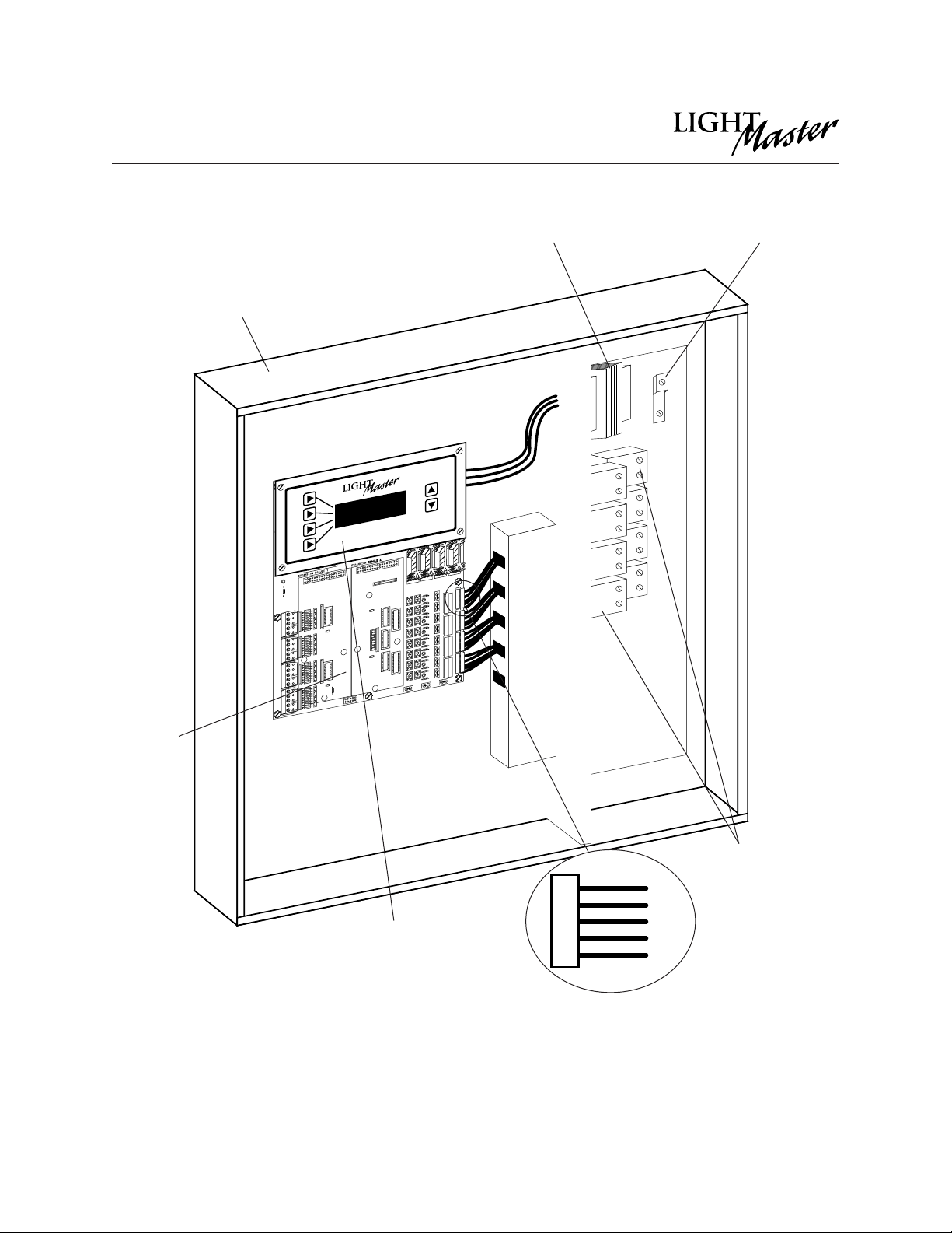
1.1.1 Enclosure - The enclosure is rated
NEMA 1. It is divided into a line voltage sec-
tion containing the line voltage side of the
control transformer and lighting relays and
a low voltage section containing the Class 2
side of the lighting relays, transformer sec-
ondary, and electronic components.
Enclosures are available in 6 sizes to accom-
modate 8, 16, 24, 32, 40 and 48 inputs, out-
puts, and lighting relays. See (Table 1-1.) The
Light Master is shipped to the job-site as a
complete assembly. (See Figure 1-1, which
illustrates a Light Master 8.)
1.1.2 Transformer - A 40 VA multi-tap control
transformer (120 or 277/24 VAC) provides
the 24 VAC input to power the controller
electronics.
Controller Description
Light Master User Manual 1 - 2
Version 1C 9/20/00
Model # of Relays
& I/O Points Width Height Depth
Light Master 8 8 18 inches 15 inches 4 inches
Light Master 16 16 24 inches 18 inches 4 inches
Light Master 24 24 24 inches 36 inches 4 inches
Light Master 32 32 24 inches 36 inches 4 inches
Light Master 40 40 24 inches 48 inches 6 inches
Light Master 48 48 24 inches 48 inches 6 inches
Table 1.1 –Light Master Configurations

1.1.3 CPU I/O Board –(See Figure 1.2.) The
CPU board provides the controller’s intelli-
gence and memory and the first eight (8) of
the controller inputs and outputs. Major
components include:
•Switch Inputs –The Light Master is designed
to accomplish a wide variety of switch
input types. See the table below for a
description of switch input types.
Controller Description
Light Master User Manual 1-3
Version 1C 9/20/00
Momentary ON/OFF: When
momentary contact is made
between ON and COM, relay
outputs controlled by this input
are turned ON. When momen-
tary contact is made between
OFF and COM, relay outputs
controlled by this input are
turned OFF.
Momentary Pushbutton:
When momentary contact is
made between ON and COM,
relay outputs controlled by this
input are turned ON and OFF
alternately each time contact
is made.
Maintained ON/OFF: When
contact is made between ON
and COM, relay outputs con-
trolled by this input are turned
ON. When contact is broken
between ON and COM, relay
outputs controlled by this input
are turned OFF.
Maintained Multi-Way: When
contact is either made or broken
between the ON and COM, relay
outputs controlled by this input
will be toggled between ON and
OFF conditions. This function is
similar to that of standard 3-
and 4-way switches.
Timed ON: When momentary
contact is made between ON
and COM, relay outputs con-
trolled by this input are turned
ON for a duration of 15 minutes
to 6 hours. At the end of this
time, relay outputs controlled by
this input are turned OFF.
Timer Disable: While contact
is made between ON and
COM, selected timer or timers
will be ignored.
Photo Sensor Inputs:
Light Master controllers can be
connected to either momentary
or maintained output photo
sensors as shown below.
Motion Sensor Inputs:
Light Master controllers can be
connected to either momentary
or maintained output motion
sensors as shown below.
Fire Alarm System Inputs:
Light Master controllers can be
easily connected to building
Fire Alarm Systems to force
selected controlled lighting cir-
cuits to the ON, OFF, or HOLD
state and lock out all other
forms of control when a Fire
Alarm signal is present (con-
tacts CLOSED).
Dry Contact Interface:
Virtually any control system or
device can be interfaced to a
Light Master controller through
the use of a simple dry contact
interface utilizing any of the
available switch types.
Please consult factory for any
special requirements.
ON
COM
OFF
ON
COM
OFF
ON
COM
OFF
ON
COM
OFF
ON
COM
OFF
ON
COM
OFF ON
COM
OFF
ON
COM
OFF
ON
COM
OFF
MAINTAINED
MAINTAINED
Programmed as
“Output Override input”
MOMENTARY
Programmed as “Momentary”
MAINTAINED
Programmed as “Maintained
ON/OFF input”
ON
COM
OFF
ON
COM
OFF
MOMENTARY
Programmed as “Momentary”
MAINTAINED
Programmed as “Maintained
ON/OFF input”
MOMENTARY MOMENTARYMAINTAINED MAINTAINED
MOMENTARY
Controller Description
Light Master User Manual 1 - 4
Version 1C 9/20/00
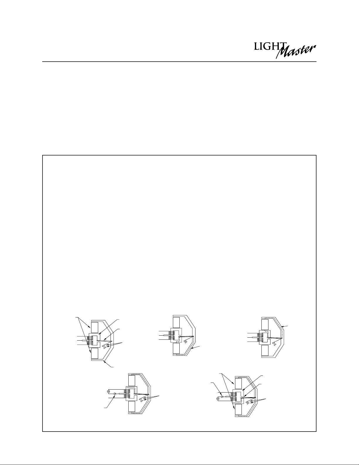
2R9 split coil relay’s unique construction has only one
movable part (the contacts). This reliable relay design
has a proven failure rate of less than 0.001 percent.
The following describes the actual internal operation
of the 2R9 relay.
Figure 1 shows the basic parts of the magnetic circuit.
The leads of the split coil are color coordinated: Red
(ON), Black (OFF), and Blue (COMMON).
The relay section consists of four permanent magnets,
a split coil switching winding, a steel bracket, a mov-
ing armature that supports the moving contacts, and
a set of stationary contacts (90% silver, 10% cadmium).
Figures 2 and 3 show the magnetic activity when no
switching is being applied. As can be observed, the
contacts are held in a steady state condition by the
permanent magnets (during a power failure the relays
will automatically maintain their state).
Magnetism Theory
By convention, magnetism “flows”FROM the north
pole TO the south pole. When a diode is placed
between the switching leads, an electromagnet is
created across the gap. By using two coils in oppo-
site directions to each other, the 2R Relay is able to
create two magnetic polarities opposite to each
other.
Figure 4 shows the magnetism that is applied to the
gap of the core to CLOSE the contacts.
When a half wave rectified source is placed between
the switching leads (current from the Red wire toward
the Blue wire), the flux that is produced sets up a mag-
netic field on both surfaces of the gap (top North and
bottom South). Because the flipper arm is always con-
nected to the North sides of the permanent magnets,
the flipper arm is repelled from the North surface and is
attracted to the South surface. The contact arm is con-
nected to the flipper arm and, therefore, the contacts
will close.
Figure 5 shows the magnetism that is applied to the
gap of the core to OPEN the contacts.
When a half wave rectified source is placed between
the switching leads (current from the Black wire
toward the Blue wire), the flux that is produced sets up
a magnetic field on both surfaces of the gap (top
North and bottom South). Because the flipper arm is
always connected to the North sides of the perma-
nent magnets, the flipper arm is repelled from the
North surface and is attracted to the South surface.
The contact arm is connected to the flipper arm and,
therefore, the contacts will open.
As can be seen by examining Figures 4 and 5, the
electromagnet reverses its polarity to switch the relay
ON and OFF.
OFF
COMM
ON
N
S
S
NMagnetic
Flux
Activity
OFF
COMM
ON
N
S
S
N
Permanent
Magnets Core
Contacts
Bracket
Switching
Leads
Armature
OFF
COMM
ON
N
S
S
N
Magnetic
Flux
Activity
Figure 2 – Magnets holding the contacts closed
Figure 1 –2R9 Relay Figure 3 –Magnets holding the contacts open
OFF
COMM
ON
N
S
S
N
24 VAC Contacts
(open)
Switching
Leads
Diode
N
S
S
N
OFF
COMM
ON 24 VAC
Magnets Core
Contacts
(closed)
Switching
Leads
Diode Gap
Figure 4 –The electromagnet and the permanent magnets
combine to switch the contacts to the closed position.
Figure 5 –The electromagnet and the permanent magnets
combine to switch the contacts to the open position.
•Relay Outputs –Each output switches its
associated lighting relay ON and OFF. Each
output has an associated LED (light emitting
diode). The LED lights when the output
switches the relay ON. The 2R9 split coil
relay’s unique construction has only one
movable part (the contacts). This reliable
relay design has a proven failure rate of less
than 0.001 percent. See below for detail.
•Override Switches –Each relay output is
equipped with an ON and an OFF override
switch. These switches allow you to turn the
associated lighting relay ON or OFF.
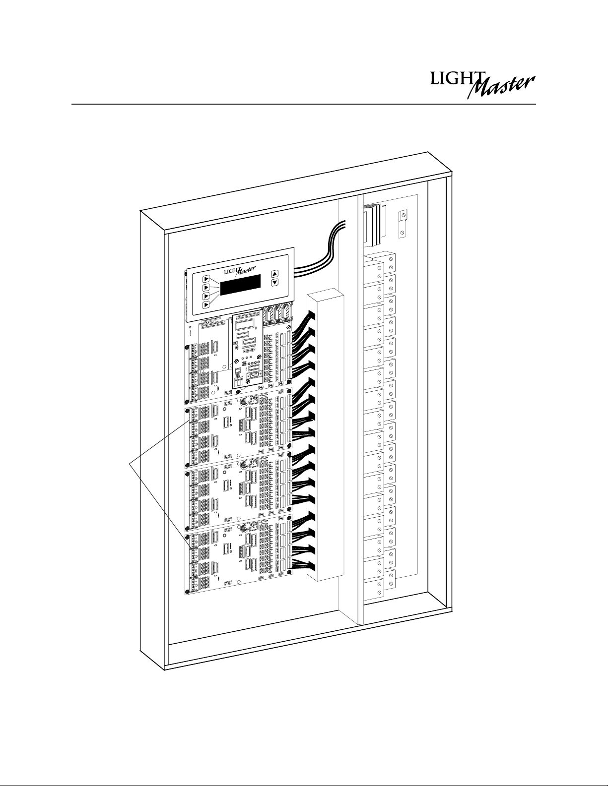
1.1.4 Additional I/O Board(s) –Additional
I/O boards composed of 8 inputs and out-
puts can be added to the appropriate size
enclosure to expand the controller capacity
up to 48 switch inputs and 48 switch relay
outputs. (See Figure 1.3, which illustrates a
Light Master 32.)
Controller Description
Light Master User Manual 1 - 5
Version 1C 9/20/00
12
34
56
78
Enclosure
Lighting relays
Relay termination detail
Programming module
CPU I/O
board
Control transformer
Figure 1.1 –Light Master 8 Controller
ORANGE
CONNECTOR
ORANGE
BLACK (OFF)
STATUS
RED (ON)
BLUE (COM)
}
Grounding Lug
Controller Description
Light Master User Manual 1 - 6
Version 1C 9/20/00
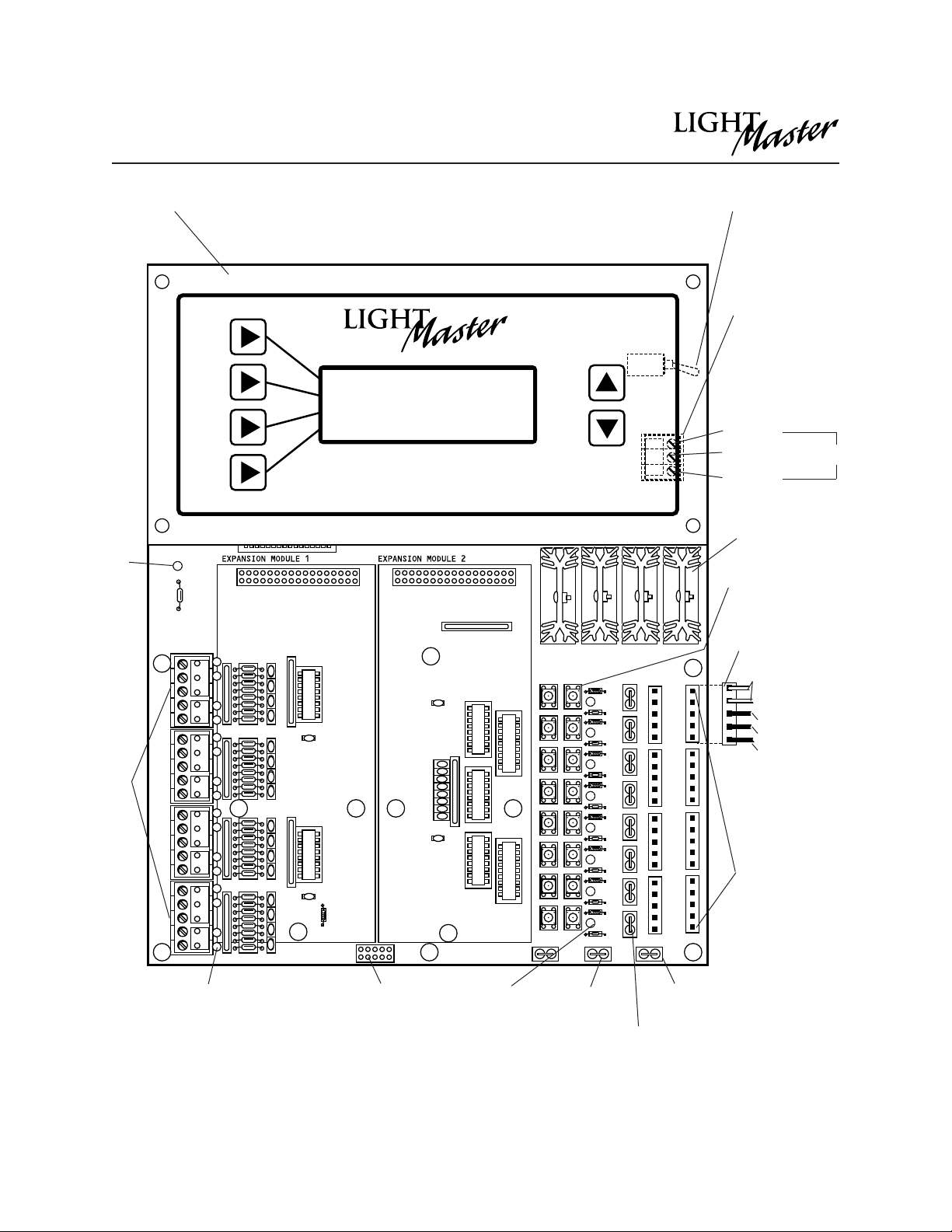
Figure 1.2 –CPU I/O Board
1 OFF
2ON
COM
2 OFF
3 OFF
3 ON
4ON
COM
4 OFF
5 OFF
5 ON
6ON
COM
6 OFF
7 OFF
7 ON
ON
COM
OFF V10
OFF
12
34
56
7
ON
OFF ON
PILOT
COM +
1ON
1
2
3
4
5
6
7
W1
Power
LED
Switch
inputs
I/O mounted
headers for
relay output
connectors
Relay output
connector
Black (OFF)
Red (ON)
Blue (COM)
Orange
(Aux. contacts : not
used on 2R7 relay)
Pilot
COM
Data to
next board
Switch input
status LEDs
Relay output
status LEDs
Power to
next board
Override
switches
Programming
module
12 VAC
Center tap
12 VAC
Main power
switch (under
Keyboard on the
controller board )
Terminal block for
transformer
(under Keyboard
on the controller
board )
LIGHT MASTER
WED 10/30/99
07:50:54 AM
EDIT (c) 99 ILC
Power
supply
ON
OFF
24 VAC
Status terminals
(used with Pilot
Light Switches)
Controller Description
Light Master User Manual 1 - 7
Version 1C 9/20/00
12
34
56
78
910
11 12
13 14
15 16
17 18
19 20
21 22
23 24
25 26
27 28
29 30
31 32
Figure 1.3 –Light Master 32
Additional
I/O boards

Controller Description
Light Master User Manual 1 - 8
Version 1C 9/20/00
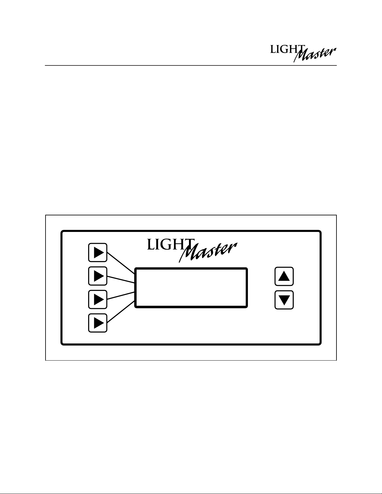
Figure 1.4 –Light Master Keypad and Display
4-line, 32-character Display Screen
Scrolling Pads
Selection Keys
(Used to select
displayed options)
1.1.5 Programming Module - (See Figure
1.4.) The programming module provides you
with access to program and view controller
data. It consists of a tactile response key-
pad and screen. The programming module
is mounted to the CPU I/O board.
1.1.6 Lighting Relays - control the line voltage
loads. The lighting relays can control 120 or
277 VAC loads rated up to 20 amps. The
Class 2 low voltage control part of each relay
is terminated to a relay output on the con-
troller CPU I/O board. (See Figure 1.2.) Each
relay output controls only one lighting relay.

1.2 I/O Options
The Light Master controller can be
equipped with the following add-on
devices:
1.2.1 Telephone Add-On Module –You can
equip the controller with a DTMF (Dual Tone
Multi Frequency) interface, which allows
you to activate switch inputs via commands
from a touchtone telephone. (See
Appendix A.)
1.2.2 PC Add-On Module –Allows for the
connection of a standard Windows-based
PC via an on-board RS232 port for monitor-
ing, control, and programming. (See
Appendix B.)
Controller Description
Light Master User Manual 1 - 9
Version 1C 9/20/00
Light Master User Manual
Version 1C 9/20/00
Section 2
Installation
LIGHT MASTER
WED 10/30/99
07:50:54 AM
EDIT (c) 99 ILC

Section 2 Installation
2.0 Section Overview .......................................................................... 2-1
2.1 Pre-Installation Checks .................................................................. 2-2
2.2 Mounting the Controller................................................................ 2-2
2.2.1 Location ................................................................................. 2-2
2.2.2 Environmental Considerations ............................................ 2-2
2.2.3 Distance From Control Devices .......................................... 2-2
2.3 Wiring the Controller...................................................................... 2-2
2.3.1 Wire the Control Transformer............................................... 2-2
2.3.2 Connect Line and Load ...................................................... 2-2
2.3.3 Wire Switch Inputs ................................................................. 2-2
2.3.4 Set Relay Response .............................................................. 2-2
2.4 Pre-Power Checks.......................................................................... 2-5
2.4.1 Check Controller Power Input............................................. 2-5
2.4.2 Verify Controller’s Supply Voltage....................................... 2-5
2.4.3 Double-Check Connections ............................................... 2-5
2.5 Power-Up and Check Out............................................................ 2-5
2.5.1 Power-Up the Controller ...................................................... 2-5
2.5.2 Verify the Lighting Relays ..................................................... 2-5
2.5.3 Perform Initial Programming Procedures........................... 2-5
2.5.4 Verify the Switching Function .............................................. 2-5
2.5.5 Verify the Timer Functions .................................................... 2-5
2.6 Troubleshooting.............................................................................. 2-6
2.6.1 Controller Will Not Power-Up ............................................... 2-6
2.6.2 Lighting Relay(s) Will Not Function...................................... 2-6
2.6.3 Switch Input Will Not Function............................................. 2-6
2.6.4 Timers Will Not Function Properly ........................................ 2-6
2.6.5 Entire I/O Board(s) Doesn’t Work ........................................ 2-6
Section 2–Table of Contents
Light Master User Manual
Version 1C 9/20/00

Objectives
This section shows you how to install the
Light Master Programmable Contactor
and how to perform required power-up
verification checks.
Overview
This section covers the following topics:
•Pre-installation checks
•Mounting the controller
•Wiring the controller
•Pre-power-up checks
•Power-up and checkout
•Troubleshooting
Section 2 –Installation
Light Master User Manual 2 - 1
Version 1C 9/20/00
This manual suits for next models
6
Table of contents
Popular Lighting Equipment manuals by other brands


ML Accessories
ML Accessories BL01BK Installation & maintenance manual

Epstein-Design
Epstein-Design Sahara E27 manual

SHAFT
SHAFT SHE191 manual

Teknoware
Teknoware ESC 90 Installation and Maintenance

Vision & Control
Vision & Control R-CLR-132x104-G523-SL Installation and operating instructions

SloanLED
SloanLED PosterBOX Mini installation guide


