Intelligent Motion Systems Microstepping MForce PowerDrive Operation manual

TM
Excellence in Motion
DESCRIPTION
The Microstepping MForce PowerDrive
is a high performance, low cost micro-
stepping driver that delivers unsurpassed
smoothness and performance achieved
through IMS’s advanced 2nd generation
current control. By applying innova-
tive techniques to control current flow
through the motor, resonance is signifi-
cantly dampened over the entire speed
range and audible noise is reduced.
Microstepping MForce PowerDrives ac-
cept a broad input voltage range from
+12 to +75 VDC, delivering enhanced
performance and speed. Oversized input
capacitors are used to minimize power
line surges, reducing problems that
can occur with long runs and multiple
drive systems. An extended operating
range of –40° to +85°C provides long
life, trouble free service in demanding
environments.
The high, per phase output current of up
to 5 Amps RMS, 7 Amps Peak, allows
the extremely compact MForce Power-
Drive to control a broad array of motors
from size 23 to size 42.
The microstepping drive accepts up to 20
resolution settings from full to 256 mic-
rosteps per full step, including: degrees,
metric and arc minutes. These settings
may be changed on-the-fly or downloaded
and stored in nonvolatile memory with the
use of a simple GUI which is provided.
This eliminates the need for external
FEATURES
•High Performance
Microstepping Driver
•Advanced 2nd Generation Current
Control for Exceptional Performance
and Smoothness
•Single Supply: +12 to +75 VDC
•Low Cost
•Compact Package
•High Output Current up to 5 Amps RMS,
7 Amps Peak (Per Phase)
•20 Microstep Resolutions up to
51,200 Steps Per Rev Including:
Degrees, Metric, Arc Minutes
•Optically Isolated Logic Inputs will
Accept +5 to +24 VDC Signals,
Sourcing or Sinking
•Automatic Current Reduction
•Configurable:
- Motor Run/Hold Current
- Motor Direction vs. Direction Input
- Microstep Resolution
- Clock Type: Step and Direction,
Quadrature, Step Up and Step Down
- Programmable Digital Filtering for
Clock and Direction Inputs
•Setup Parameters May Be Switched
On-The-Fly
•Dual Mounting Configurations
•Interface via
Pluggable Locking Wire
Crimp Connectors
•Graphical User Interface (GUI) for
Quick and Easy Parameter Setup
www.imshome.com
switches or resistors. Parameters are
changed via an SPI port.
The versatile Microstepping MForce
PowerDrive comes with dual mounting
configurations to fit various system needs.
All interface connections are accomplished
using pluggable locking wire crimp connec-
tors. Optional cables are available for ease
of connecting and configuring the MForce,
and are recommended with first order.
The Microstepping
MForce PowerDrive
is a compact, powerful and inexpensive
solution that will reduce system cost,
design and assembly time for a large
range of applications.
CONFIGURING
The IMS SPI Motor Interface software is
an easy to install and use GUI for con-
fi g uring Microstepping MForce from a
computer's USB port. GUI access is via
the IMS SPI Motor Interface included on
the CD shipped with the product, or from
www.imshome.com.
The IMS SPI Motor Interface features:
• Easy installation.
•
Automatic detection of MForce version
and communication configuration.
• Will not set out-of-range values.
• Tool-tips display valid range
setting for each option.
• Simple screen interfaces.
TM
FORCE
POWER DRIVE
MICROSTEPPING
2 MForce PowerDrive – Microstepping REV052307
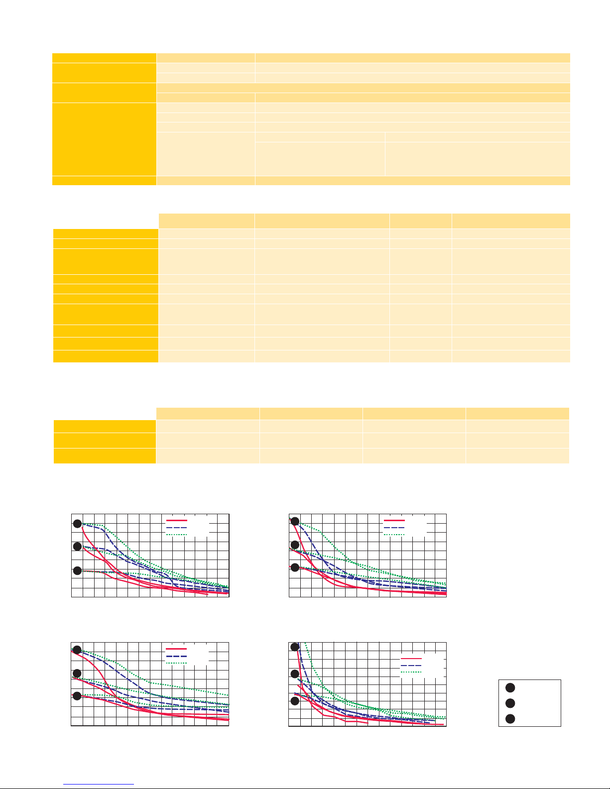
MOTOR PERFORMANCE — Speed-Torque
MForce PowerDrive
–
MICROSTEPPING
INPUT VOLTAGE (+V) Range +12 to +75 VDC
OUTPUT CURRENT RMS (Max) 5 Amps
Peak (Per Phase) 7 Amps
ISOLATED INPUT
Step Clock, Direction and Enable
Voltage Range +5 to +24 VDC Sourcing or Sinking
MOTION
Digital Filter Range 50 nS to 12.9 µS (10 MHz to 38.8 kHz)
Clock Types Step/Direction, Quadrature, Step Up/Step Down
Step Frequency 2 MHz Default (5 MHz Max)
Resolution
Number of Settings 20
Steps Per Revolution
200,
400, 800, 1000, 1600, 2000, 3200, 5000,
6400, 10000, 12800,
20000
, 25000, 25600,
40000, 50000, 51200, 36000 (0.01 deg/µstep),
21600 (1 arc minute/µstep), 25400 (0.001mm/µstep)
THERMAL Heat Sink Temperature –40° to +85°C
STANDARD SPECIFICATIONS
SETUP PARAMETERS
Function Range Units Default
MHC Motor Hold Current 0 to 100 percent 5
MRC Motor Run Current 1 to 100 percent 25
MSEL Microstep Resolution
1, 2, 4, 5, 8, 10, 16, 25, 32, 50,
64, 100, 108, 125, 127, 128, 180,
200, 250, 256
µsteps per full
step 256
DIR Motor Direction Override 0/1 — CW
HCDT Hold Current Delay Time 0 or 2–65535 mSec 500
CLK TYPE Clock Type Step/Dir, Quadrature, Up/Down — Step/Dir
CLK IOF Clock and Direction Filter 50 nS to 12.9 µS
(10 MHz to 38.8 kHz) nS ( MHz) 200 nS (2.5 MHz)
USER ID User ID Customizable 1–3 characters IMS
EN ACT Enable Active High/Low — High
WARN TEMP Over Temperature Warning 0 to 125°C °C 80°C
All parameters are set using the supplied IMS SPI Motor Interface GUI and may be changed on-the-fly.
An optional Parameter Setup Cable is recommended with first orders.
MOTOR RECOMMENDATIONS
IMS PART NUMBERS Size 23 (2.4 Amps) Size 23 (3.0 Amps) Size 23 (6.0 Amps) Size 34 (6.4 Amps)
SINGLE LENGTH
M-2218-2.4 M-2218-3.0 M-2218-6.0 M-3424-6.3
DOUBLE LENGTH
M-2222-2.4 M-2222-3.0 M-2222-6.0 M-3431-6.3
TRIPLE LENGTH
M-2231-2.4 M-2231-3.0 M-2231-6.0 M-3447-6.3
200
225
175
150
125
100
75
50
25
0
141
159
124
106
88
71
53
35
18
0
Torque in Oz - In
Torque in N - cm
24 VDC
45 VDC
75 VDC
1000
(300)
2000
(600)
3000
(900)
4000
(1200)
5000
(1500)
6000
(1800)
7000
(2100)
Speed in Full Steps per Second (RPM)
C
B
A
NEMA 23 — 2.4 Amps RMS
200
225
175
150
125
100
75
50
25
0
141
159
124
106
88
71
53
35
18
0
Torque in Oz - In
Torque in N - cm
24 VDC
45 VDC
75 VDC
1000
(300)
2000
(600)
3000
(900)
4000
(1200)
5000
(1500)
6000
(1800)
7000
(2100)
Speed in Full Steps per Second (RPM)
C
B
A
NEMA 23 — 3.0 Amps RMS
200
225
175
150
125
100
75
50
25
0
141
159
124
106
88
71
53
35
18
0
Torque in Oz - In
Torque in N - cm
24 VDC
45 VDC
75 VDC
1000
(300)
2000
(600)
3000
(900)
4000
(1200)
5000
(1500)
6000
(1800)
7000
(2100)
Speed in Full Steps per Second (RPM)
C
A
B
NEMA 23 — 6.0 Amps RMS NEMA 34 — 6.3 Amps RMS
900
1000
800
700
600
500
400
300
200
100
00 1000
(300)
2000
(600)
3000
(900)
4000
(1200)
5000
(1500)
6000
(1800)
7000
(2100)
Speed in Full Steps per Second (RPM)
Torque in Oz - In
Torque in N - cm
465
494
423
706
635
353
282
211
140
71
45 VDC
75 VDC
24 VDC
C
B
A
A
B
C
Single Stack
Double Stack
Triple Stack

MForce PowerDrive – Microstepping REV052307 3
PIN ASSIGNMENTS
ORDER INFORMATION
OPTIONS
Motors and Encoders
IMS offers a wide range of motors, encoders and accessories
recommended for interface with the Microstepping MForce
PowerDrive. For complete specifications on these products,
please visit the IMS web site at www.imshome.com.
Power Supplies
IMS recommends the following power supplies for operat-
ing the MForce PowerDrive: IP804, IP806, ISP300-7. For
complete specifications, go to www.imshome.com
ACCESSORIES
Parameter Setup Cable and Adapter
The optional 12.0' (3.6m) parameter setup cable and adapter,
MD-CC300-000 and MD-ADP-1723C, facilitate communica-
tions interface from the Microstepping MForce PowerDrive's
12-pin P1 connector to a PC's USB port with pluggable mating
connectors. Recommended with first order.
Prototype Development Cables
To speed prototyping, 10.0' (3.0m) development cables are
available with pluggable locking wire crimp mates to:
I/O & Comm: 12-Pin Connector ........... PD12-1434-FL3
Power: 2-pin Connector ...................... PD02-3400-FL3
Motor Interface: 4-pin Connector
............ PD04-MF34-FL3
Accessories details at: www.imshome.com/cables_cordsets.html
MECHANICAL SPECIFICATIONS
Dimensions in Inches (mm)
3.473
(88.21)
2X 0.580
(2X 14.73) Ø 0.187 ±0.01
(Ø 4.75 ±0.25)
2X #8 Screws
for End Mount
3.00 ±0.01
(76.2 ±0.25)
2.116
(53.75)
0.225
(5.72)
P4
P3
P1
BOTTOM VIEW
FRONT VIEW
3.473
(88.21)
Ø 0.160 ±0.01 Thru
(Ø 4.06 ±0.25 Thru)
4X #6 Screws
for Flat Mount
0.308 TYP.
(7.82 TYP.)
2.931 TYP.
(74.45 TYP.)
3.897
(98.98)
0.417 TYP.
(10.59 TYP.)
0.160 ±0.01
(4.06 ±0.25)
2.950
(74.93)
P1: I/O & COMM CONNECTOR
Pluggable Locking Wire Crimp Function
Pin 1 No Connect
Pin 2 No Connect
Pin 3 Optocoupler Reference
Pin 4 Step Clock Input
Pin 5 Enable Input
Pin 6 CW/CCW Direction Input
Pin 7 +5 VDC Output
Pin 8 SPI Clock
Pin 9 Communications Ground
Pin 10 SPI Master Out – Slave In
Pin 11 SPI Chip Select
Pin 12 SPI Master In – Slave Out
P4: MOTOR CONNECTOR
Pluggable Locking Wire Crimp
Function
Pin 1 Phase A
Pin 2 Phase /A
Pin 3 Phase B
Pin 4 Phase /B
P3: POWER CONNECTOR
Pluggable Locking Wire Crimp
Function
Pin 1 +V (+12 to +75 VDC)
Pin 2 Power/Aux Ground
MFM1CSZ34
N7
Example: Part Number
MFM1CSZ34N7
is a
Microstepping MForce
PowerDrive with 12-pin
I/O & SPI communications
interface, 2-pin power interface
and 4-pin motor interface.
P1: I/O & Communications
12-Pin Locking Wire Crimp
P3: Power
2-Pin Locking Wire Crimp
P4: Motor Interface
4-Pin Locking Wire Crimp
TM
FORCE
POWER DRIVE
MICROSTEPPING

TECHNICAL SUPPORT (U.S.A.)
Phone: 860/295-6102
Fax: 860/295-6107
IMS ASIA PACIFIC OFFICE
30 Raffles Pl., 23-00 Caltex House
Singapore 048622
Phone: +65/6233/6846
Fax: +65/6233/5044
IMS EUROPEAN SALES MGT.
4 Quai Des Etroits
69005 Lyon, France
Phone: +33/4 7256 5113
Fax: +33/4 7838 1537
IMS UK Ltd.
25 Barnes Wallis Road
Segensworth East
Fareham, Hampshire PO15 5TT
Phone: +44/0 1489-889825
Fax: +44/0 1489-889857
intelligent motion systems, INC.
Excellence in Motion
www.imshome.com
© Intelligent Motion Systems, Inc. All Rights Reserved. REV052307
IMS Product Disclaimer and most recent product information at www.imshome.com.
U.S.A. SALES OFFICES
Eastern Region
Phone: 973/661-1270
Fax: 973/661-1275
Central Region
Phone: 260/402-6016
Fax: 419/858-0375
Western Region
Phone: 602/578-7201
E-mail:
370 N. Main St., P.O. Box 457
Marlborough, CT 06447 U.S.A.
Phone: 860/295-6102
Fax: 860/295-6107
E-mail: [email protected]
DISTRIBUTED BY:
This manual suits for next models
2
Table of contents
Other Intelligent Motion Systems Home Safety Product manuals

Intelligent Motion Systems
Intelligent Motion Systems MDI42 AC User manual

Intelligent Motion Systems
Intelligent Motion Systems MDI34 User manual

Intelligent Motion Systems
Intelligent Motion Systems MDrive34AC Plus2-65 User manual

Intelligent Motion Systems
Intelligent Motion Systems MDI AC42Plus MDrive42AC User manual
Popular Home Safety Product manuals by other brands

First Alert
First Alert EL52 user manual

GE
GE 45132 user manual

Portfolio
Portfolio Motion Sensing Porch Light PF-4300-BK owner's manual

YachtSafe
YachtSafe W030 manual

Heath Zenith
Heath Zenith Motion Sensing Porch Light SL-4303 owner's manual

Heath Zenith
Heath Zenith Motion Sensor Light Control 5408 / 5410 owner's guide
