Intellijel Tetrapad User manual

Tetrapad Manual
Tetrapad
Multi-Dimensional Performance Touch Controller
Firmware: 1.0
Manual Revision: 2017.11.14

Tetrapad Manual
Table of Contents
Table of Contents
Overview
Installation
Before Your Start
Installing Your Module
Panel Reference
Modes Overview
Selecting Modes
Auto-Saving
Mode Reset
Mode 1: Faders Mode
Using Faders Mode
Slew Between Fader Settings
Freeze All Faders
Mode 2: Voltages Mode
Using Voltages Mode
Edit a Button’s Stored Voltages
Randomize a Single Stored Voltage
Randomize all 8 Stored Voltages for a Button
Reset a Stored Voltage to 0V
Slew Between Stored Voltages
Mode 3: Keyboard Mode
Using Keyboard Mode
EDIT VIEW: Assigning Keys According to Scale
PERFORMANCE VIEW: Playing the Keyboard
Slew Between Notes
Mode 4: Custom Keyboard Mode
Page 1

Tetrapad Manual
Using Custom Keyboard Mode
Manual Note Assignment
Slew Between Notes
Playing the Keyboard
Mode 5: Drum Mode
Using Drum Mode
Mode 6: LFO Mode
Using LFO Mode
Using LFO EDIT View
Using LFO PERFORMANCE Mode
Mode 7: Switches Mode
Using Switches Mode
Mode 8: Chord Mode
Using Chord Mode
Chord Selection
Slew Between Chords
Performing in Chord Mode
Mode 9: Custom Chord Mode
Using Custom Chord Mode
Note Entry
Slew Between Chords
Performing in Custom Chord Mode
Mode 12: Global Configuration
Using Global Configuration Mode
Firmware Change Log
Technical Specifications
Page 2

Tetrapad Manual
Overview
Tetrapad is a versatile, multi-dimensional, touch-sensitive control surface for Eurorack. Each
of its four pads use force sensing resistors to respond to both the vertical position of your
finger and its pressure. Four push encoders and a shift function give you even more tactile
control over your modular system.
Tetrapad operates in numerous modes — each of which configures the module to perform a
specific control task. Through these modes, Tetrapad can emulate a bank of faders; a
voltage storage device; a finger drumming surface; a chord generator; an 8-key keyboard;
four independent LFOs; or an 8-switch panel. The chosen mode determines what type of
signal (CV, note, trigger, gate, etc.) is sent from each of Tetrapad’s eight independent
outputs, while its multitude of multi-colored LEDs keep you informed of exactly what’s
happening within each mode.
Tetrapad automatically remembers how you’ve configured each of its modes, and retains
these settings when powered off. By default, Tetrapad automatically saves its settings every
minute, or whenever you change modes. This makes Tetrapad ideal for live performance,
since you know it will always power up in its most recently saved state.
Page 3

Tetrapad Manual
Installation
Intellijel Eurorack modules are designed to be used with a Eurorack-compatible case and
power supply.
Before Your Start
Before installing a new module in your case you must ensure your case’s power supply has
sufficient available capacity to power the module:
● Sum up the specified +12V current draw for all modules, including the new one. Do the
same for the -12 V and +5V current draw. The current draw will be specified in the
manufacturer's technical specifications for each module.
● Compare each of the sums to specifications for your case’s power supply.
● Only proceed with installation if none of the values exceeds the power supply’s
specifications. Otherwise you must remove modules to free up capacity or upgrade your
power supply.
You will also need to ensure you have enough free space (hp) as well as free power
headers in your case to fit the new module.
You can use a tool like ModularGrid to assist in your planning. Failure to adequately power
your modules may result in damage to your modules or power supply. If you are unsure,
please contact us before proceeding.
Installing Your Module
When installing or removing a module from your case always turn off the power to the case
and disconnect the power cable. Failure to do so may result in serious injury or equipment
damage.
Ensure the 10-pin connector on the power cable is connected correctly to the module before
proceeding. The red stripe on the cable must line up with the -12V pins on the module’s
power connector. The pins are indicated with the label -12V, a white stripe next to the
connector, the words “red stripe”, or some combination of those indicators.
Page 4

Tetrapad Manual
Most modules will come with the cable already connected but it is good to double check the
orientation. Be aware that some modules may have headers that serve other purposes so
ensure the cable is connected to the right one.
The other end of the cable, with a 16-pin connector, connects to the power bus board of
your Eurorack case. Ensure the red stripe on the cable lines up with the -12V pins on the
bus board. On Intellijel power supplies the pins are labelled with the label “-12V” and a thick
white stripe:
Page 5

Tetrapad Manual
If you are using another manufacturer’s power supply, check their documentation for
instructions.
Once connected, the cabling between the module and power supply should resemble the
picture below:
Before reconnecting power and turning on your modular system, double check that the
ribbon cable is fully seated on both ends and that all the pins are correctly aligned. If the
pins are misaligned in any direction or the ribbon is backwards you can cause damage to
your module, power supply, or other modules.
After you have confirmed all the connections, you can reconnect the power cable and turn
on your modular system. You should immediately check that all your modules have powered
on and are functioning correctly. If you notice any anomalies, turn your system off right away
and check your cabling again for mistakes.
Page 6
Tetrapad Manual
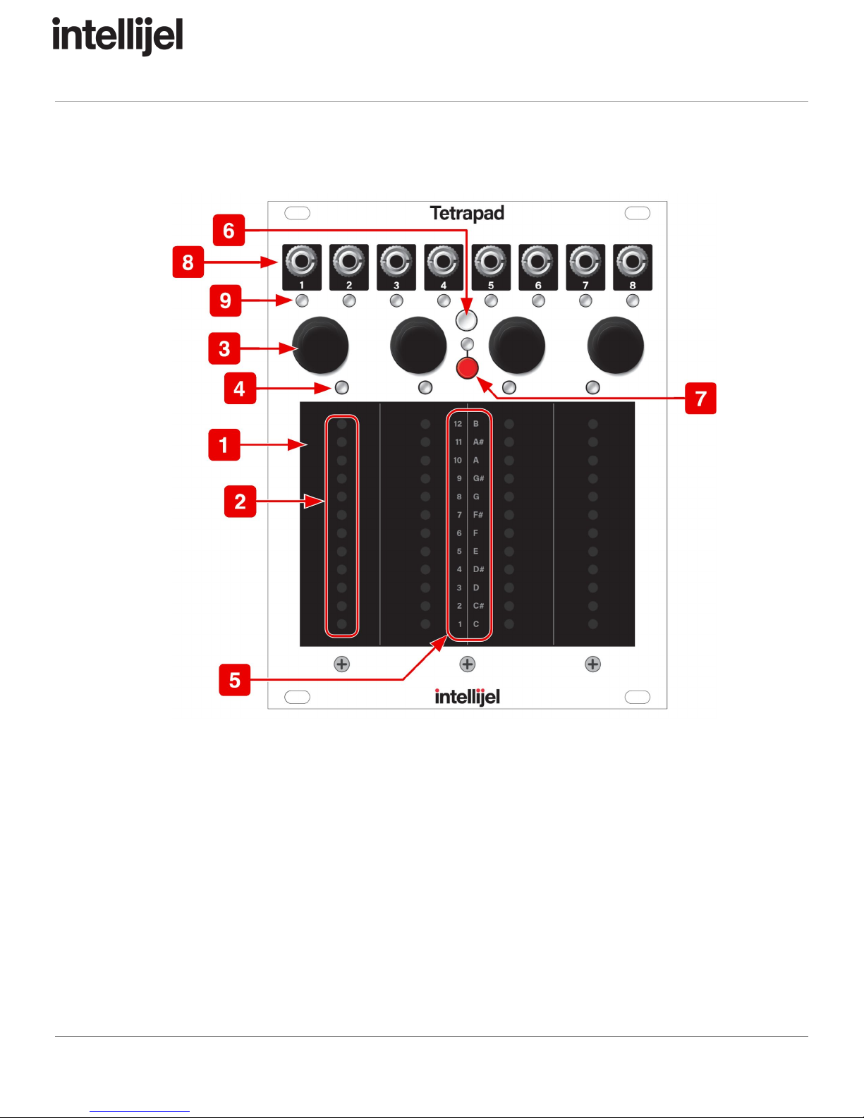
Panel Reference
1. Pads 1-4
Four identical touch strips, each of which is sensitive to both vertical position and
finger pressure. Depending on Tetrapad’s current mode, these pads can transmit
trigger signals, gate signals, quantized note values or CV in real time.
2. Level LEDs
Embedded beneath the surface of each pad is a 12 LED ladder. This ladder displays
different parameter values in different modes. When operating as basic faders, the
LEDs represent the level of each fader; when operating as note triggers, they
represent the note value; when selecting modes, they represent the mode number.
Page 7

Tetrapad Manual
3. Push Encoders 1-4
Each of the four pads has its own associated push encoder, which functions
differently depending on Tetrapad’s current mode. For example, in Custom Chord
Mode, the encoders assign a note value to each output. In LFO Mode, the encoders
select the pad’s waveform shape. Similarly, pressing the encoder has different
functions depending on the mode. For example, in Faders Mode, pressing an
encoder latches the corresponding fader’s value. Not every pad uses the encoders,
so please read the specific mode discussions to learn what functions are performed
for each mode.
4. Pad Status LEDs 1-4
Some modes use these LEDs to indicate a pad’s status. For example, they may
indicate whether or not a pad’s fader level is latched; or to which octave a note
belongs.
5. Level Labels
This vertical column of text provides meaningful labels to each of the 12 vertically
stacked Level LEDs. On the left are numbers 1-12, which indicate mode numbers.
On the right are note names, which indicate pitch when appropriate to the selected
mode.
6. Mode Select Button
Toggles Mode selection on and off. When Mode Select is on, the eight Output Status
LEDs light up, and the Level LEDs within each of the four pads also light to indicate
which mode is currently selected. To select different modes, rotate any of the four
encoders — all four Level LEDs move up/down to indicate the mode number. Press
the Mode Select button again (or press any encoder) to exit mode selection.
7. Shift Button & LED
Some modes offer additional feature sets, which are accessed by pressing the Shift
Button. For example, LFO Mode’s shift feature switches between Performance and
Edit views. See the individual mode discussions to learn whether or not the Shift
button is used, and what function it serves. The LED immediately above the Shift
button glows green whenever a mode contains a shift feature, and it glows red when
the shift feature is engaged. If the Shift LED is off, then the mode has no shift
feature.
Page 8
Tetrapad Manual
8. Outputs 1-8
Outputs CV, pitch, gate or trigger signals depending on the active mode. See the
Modes section to learn the function of each jack in each mode
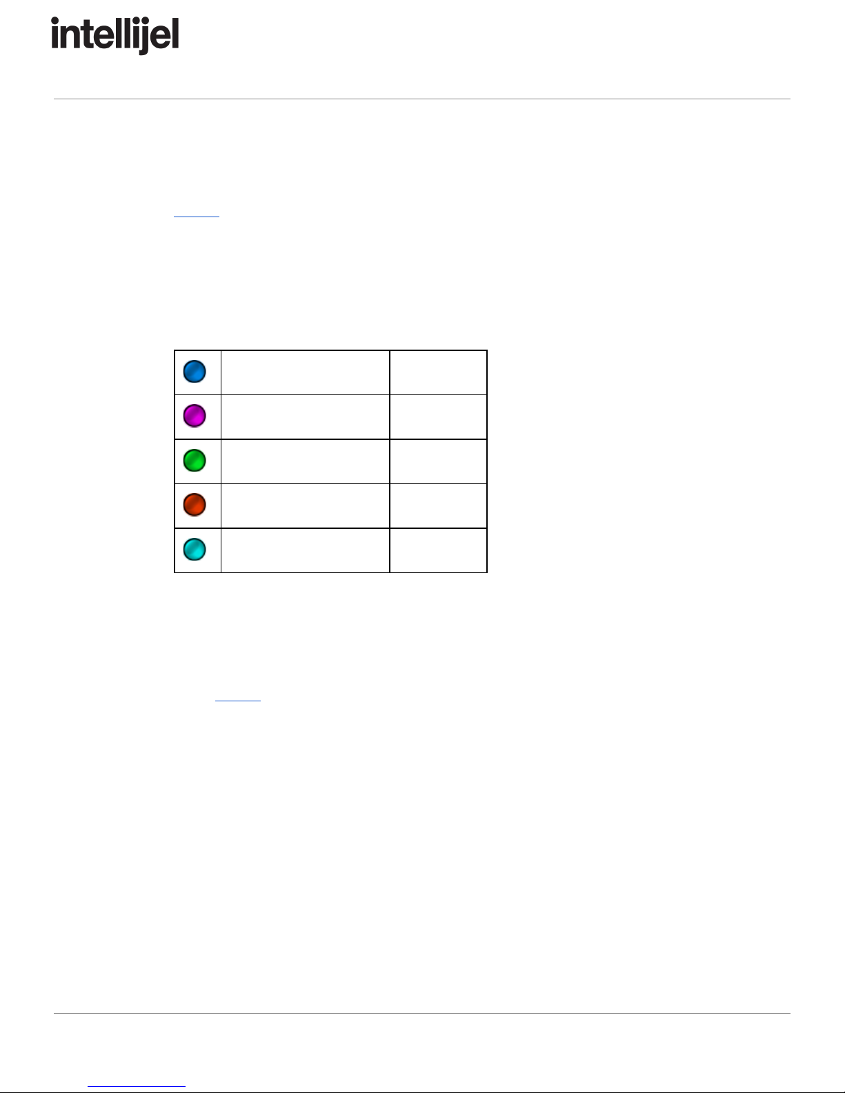
9. Output Status LEDs
These LEDs serve two functions, depending on whether you’re selecting modes, or
actually using a particular mode. When selecting
modes, the color of these LEDs
glow solid and indicate the type of signal appearing at the output jack for the selected
mode:
Pitch CV
Blue
Gate/Trigger
Magenta
Vertical Position
Green
Pressure
Red
Other CV (i.e. LFO)
Cyan
When using
a mode, both the color and the brightness of the LEDs provide output
status information. For example, a green (position) LED gets brighter when your
finger is higher up the pad; a red (pressure) LED gets brighter the harder you press a
pad; Other modes make additional use of these status LEDs, and will be discussed
in the Modes section of this manual.
Page 9

Tetrapad Manual
Modes Overview
We designed Tetrapad to provide you with tactile control of your modular synth, plus the
ability to maximize the flexibility with which you wield that control. For this reason, Tetrapad
is a mode-based control surface. Each mode reassigns the four touch pads, four rotary push
encoders, eight outputs, numerous status LEDs and shift button.
Tetrapad currently supports nine different modes (plus a separate global configuration
mode) — each designed to operate as a tactile control surface best-suited for its intended
task. These modes are:
●Mode 1: Faders Mode - This mode gives you 4 pressure sensitive faders, which means
each fader can generate two control voltages: one based on the vertical position of your
finger; and one on pressure.
●Mode 2: Voltages Mode - Voltages Mode divides each pad into two regions — an upper
and a lower — giving you access to 8 voltage banks, each of which can store 8 voltages
(one for each output).
●Mode 3: Keyboard Mode - Keyboard Mode turns Tetrapad into an 8-key keyboard, with
each key capable of sending a different note to Outs 1-4. This mode divides each of the
four pads in two, creating an upper key and a lower key. Touching any pad also outputs
both a trigger and a gate signal, and pads respond to both position and pressure. You
define notes for each key by selecting a keyboard mapping from the built-in Scale
Library and you set a root note with a twist of an encoder. Diatonically shifted versions of
the root scale appear at each of the four outputs and you can rotate these assignments
using another encoder.
●Mode 4: Custom Keyboard Mode - Custom Keyboard Mode is similar to Keyboard
Mode (described above), only instead of automatically assigning keys to a particular
scale, you manually assign a note to each of the eight keys (and for each of the four
outputs, if you wish). Custom Keyboard Mode is for people who want direct control over
the pitch of every key and output, and don’t wish to be constrained by the scales
included in Mode 3’s Scale Library.
●Mode 5: Drum Mode - Drum Mode provides you with four positionally sensitive drum
pads. Each pad generates a gate signal when touched, plus a second CV based on the
vertical position of your finger. Since each pad generates a gate no matter where you
tap it, this mode is ideal for “finger” drumming, but with the possibility of additional
expression via the positional output CV.
●Mode 6: LFO Mode - LFO mode turns Tetrapad into four independent LFO’s, each with
its own rate and waveshape, and with each pad offering a pressure output for additional
modulation options.
Page 10

Tetrapad Manual
●Mode 7: Switches Mode - In this mode, Tetrapad becomes an 8-switch control panel,
which you can configure as either toggle switches or momentary switches.
●Mode 8: Chord Mode - Chord Mode stores a unique 4-note chord for each of the four
pads. Touching a pad transmits the four notes to the first four outputs, enabling you to
play one-finger chords (if you use multiple oscillators). Touching any pad also outputs
both a trigger and a gate signal, and pads respond to both position and pressure. Define
a chord for each pad by selecting it from the built-in Chord Library, and alter the root
note, inversion and chord rotations using the encoders.
●Mode 9: Custom Chord Mode - Custom Chord Mode is similar to Chord Mode
(described above), only instead of using the encoders to select chords, roots, inversions
and rotations, you manually assign — pad-by-pad and output-by-output — each note in
each chord. Custom Chord Mode is for people with chord requirements that extend
beyond those included in Mode 8’s Chord Library.
In addition, there is a special global configuration mode, which is assigned to Mode 12:
●Mode 12: Global Configuration - This is a “special” mode, which you use to configure
Tetrapad’s pressure response to match your own preferences. Unlike the first eight
modes, Global Configuration mode is not meant for performance nor for controlling other
modules.
Selecting Modes
To select different modes on Tetrapad:
1. Press the white Mode Select button to enter Mode Selection.
2. Rotate any of the four encoders to select the desired mode.
The Level LEDs embedded beneath each pad will move up or down the pads. The
position number (as indicated by the Level Labels in the middle of the Tetrapad)
corresponds to the mode. So if the row of Level LEDs next to Level Label 4 is lit,
then you’re selecting Mode 4; if the row of Level LEDs next to Level Label 7 is lit,
then you’re selecting Mode 7; etc.
Note that the eight Output Status LEDs will change colors as you cycle through the
modes. These colors indicate what type of signal appears at each output for each
mode. These will be discussed in the mode-specific sections of this manual.
3. Press the white Mode Select button again to exit mode selection.
Your Tetrapad will now operate in this mode. Note that you can also click any of the
four encoders to exit mode selection.
Page 11

Tetrapad Manual
TIP:
If
you
forget
what
type
of
signal
appears
at
each
of
the
eight
output
jacks,
simply
press
the
white
Mode
Select
button
—
the
LEDs
under
each
jack
light
to
indicate
the
type
of
signal
present
at
that
jack
(as
discussed
earlier,
under
“Output
Status
LEDs”).
Press
the
Mode
Select
button
again
to
exit
mode
selection.
Auto-Saving
Tetrapad automatically remembers how you’ve configured each of its modes, and it retains
these settings when powered off. By default, Tetrapad automatically saves its settings every
minute, or whenever you change modes. This makes Tetrapad ideal for live performance,
since 1) you know it will always power up in its most recently saved state, with all your
modes intact, and 2) you can switch freely between modes in a performance, and know that
each mode will always be set exactly the way you last left it.
Mode Reset
In spite of the obvious advantages gained by Tetrapad’s Auto-Save feature, you may
sometimes prefer to program a mode “from scratch” rather than modifying a previously
saved configuration. For this reason, Tetrapad provides a Mode Reset feature:
1. Press the white Mode Select button to enter Mode Selection, and rotate any of the four
encoders to select the mode you wish to reset.
2. Press the red Shift button and, while holding it down, exit Mode Selection (by clicking
either the white Mode Select button or any of the four push encoders).
Tetrapad resets that mode to the factory default settings.
NOTE:
You
can
also
reset
all
Modes
simultaneously
(along
with
the
Global
Configuration
Settings)
by
using
this
same
technique
with
Mode
12
selected.
Page 12

Tetrapad Manual
Mode 1: Faders Mode
Press the white Mode Select button and rotate any of the four encoders to select Mode 1,
which occurs when the row of Level LEDs light next to Level Label 1. Press the white Mode
Select button again (or press any encoder) to exit mode selection.
Faders Mode gives you 4 pressure sensitive faders, which means each fader can generate
two control voltages: one based on the vertical position of your finger; and one on pressure.
Page 13

Tetrapad Manual
Using Faders Mode
1. Slide a finger up and down each pad, just as if you were moving an actual fader.
Alternately, you can simply tap a pad anywhere along its vertical scale, and the fader will
jump to that level directly (using a slew rate you define, as discussed shortly).
Tetrapad sends each fader’s vertical position CV to its odd numbered output. That is,
Pad 1 sends fader values to Out 1; Pad 2 sends fader values to Out 3; etc. Each
Output Status LED lights green to represent the presence of a CV signal, while the
brightness of each LED indicates its absolute value, from 0 to +5V.
2. Press down on a pad to send an additional pressure-sensitive CV to the corresponding
even numbered output.
That is, Pad 1 sends its pressure value to Out 2; Pad 2 sends it to Out 4; etc. Each
Output Status LED lights red to represent the presence of a pressure CV signal,
while the brightness of each LED indicates its absolute value, from 0 to +5V.
3. Press a fader’s corresponding encoder to latch that fader.
Latched faders are indicated by a blue Pad Status LED and can be assigned on a
fader-by-fader basis. When a fader is latched, it remains at the last level touched —
much like a real fader on an analog mixing console. When a fader is unlatched (the
Status LED is off), it snaps back to its minimum value when you release it — much
like the spring-loaded modulation wheel used by some synths.
Page 14

Tetrapad Manual
Slew Between Fader Settings
If you prefer to tap faders (rather than drag them) or if you use latch mode, you’ll appreciate
the ability to set the rate at which fader values move from one touched level to the next.
Each of Tetrapad’s four faders can have its own slew rate.
1. Hold down the red SHIFT button and rotate the encoder above each fader to set its slew
rate.
Clockwise turns increase the time it takes to move from one fader value to another
(up to a maximum of about 4 sec to move between min/max levels).
Counterclockwise turns decrease the amount of time it takes to move from one fader
value to another (down to “instantaneous”).
Slew times are indicated by a red Pad Status LED above each fader — with an LED
glowing increasingly brighter as the slew gets longer. Since latched faders cause the
Pad Status LED to turn blue, slew rates applied to a latched fader cause increasing
amounts of red to mix with the blue LED, ultimately resulting in a purple LED at
maximum slew rate.
Freeze All Faders
You can freeze the position and pressure level of each fader at its current level.
1. Press the red Shift button to freeze the output of each fader (including its pressure
value).
The Shift LED will glow blue, and any faders currently slewing to a new value will be
frozen mid-slew. Any currently unlatched faders will also freeze at the current
position of your finger, regardless of whether they’re latched or not.
2. Press the red Shift button again to unfreeze the faders.
Page 15

Tetrapad Manual
Mode 2: Voltages Mode
Press the white Mode Select button and rotate any of the four encoders to select Mode 2,
which occurs when the row of Level LEDs light next to Level Label 2. Press the white Mode
Select button again (or press any encoder) to exit mode selection.
Voltages Mode divides each pad into two regions — an upper and a lower — giving you
access to 8 stored voltages per OUTPUT! That’s right, each of Tetrapad’s eight outputs has
its own bank of 8 virtual buttons, each of which can store a voltage value specifically for that
output, meaning you have 64 voltage storage locations in total.
Page 16
Tetrapad Manual
Imagine pushing a single button that sends one voltage to a filter’s frequency, another
voltage to resonance, a third to a Quadra Expander’s attack CV and a fourth to its decay
CV. You could use the fifth output to change waveshapes on a Shapeshifter, and the sixth to
set the amount of wave folding. Output 7 could change the grain size in Rainmaker, while
Out 8 could adjust its wet/dry mix. In other words, used this way, Voltages Mode is almost
like having patch memory within Eurorack.
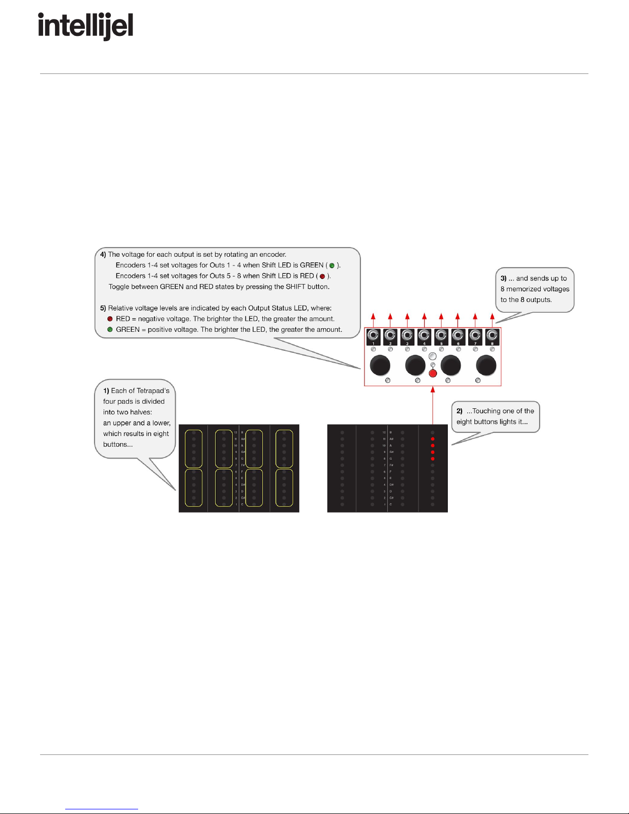
Using Voltages Mode
Each pad is divided into two regions: an upper and a lower, meaning you have eight voltage
storage locations, each accessed by its own virtual “button.”
1. Touch one of the eight virtual buttons to transmit up to eight different voltage values from
each of Tetrapad’s eight outputs.
Notice that a group of four Level LEDs light on the pad, indicating which virtual
button you just touched.
Page 17

Tetrapad Manual
Edit a Button’s Stored Voltages
1. Touch one of Tetrapad’s eight virtual buttons to select it for editing (each of the four pads
is divided into two regions: an upper half and a lower half, giving eight virtual buttons).
2. To assign voltages to Outputs 1 - 4, make sure the Shift LED is green, then rotate
encoders 1 - 4, which assigns voltages to Outputs 1 - 4 respectively.
NOTE:
If
the
Shift
LED
is
currently
red,
push
the
Shift
button
to
toggle
it
to
the
green
state)
Turning an encoder clockwise assigns increasingly higher positive voltages (up to +5
V), which are indicated by the intensity of the Output Status LED, which glows green
to indicate that the voltage is positive.
Turning an encoder counter-clockwise sets increasingly larger negative voltages (up
to -5 V), which are indicated by the intensity of the Output Status LED, which glows
red to indicate the voltage is negative.
3. To assign voltages to Outputs 5 - 8, make sure the Shift LED is red, then rotate
encoders 1 - 4, which assigns voltages to Outputs 5 - 8 respectively.
NOTE:
If
the
Shift
LED
is
currently
green,
push
the
Shift
button
to
toggle
it
to
the
red
state.
Randomize a Single Stored Voltage
Those of you who prefer the serendipity approach to sound design will appreciate
Tetrapad’s random voltage assignment feature. To randomize a single output voltage:
1. Touch and hold the desired button (do not release your finger from the pad). Then, with
your finger still on the virtual button, rotate the encoder assigned to the output you wish
to randomize.
For example, if you hold your finger on the top left virtual button while turning
Encoder #2, then with each click of the encoder, you will assign a new random
voltage to Output 2 (or Output 6 if the Shift LED is red).
Page 18

Tetrapad Manual
Randomize all 8 Stored Voltages for a Button
Those of you who prefer the serendipity approach to sound design and who like it applied
judiciously will appreciate this feature, which lets you select a virtual button and randomize
all 8 Outputs simultaneously.
1. Touch and hold the desired button (do not release your finger from the pad). Then, with
your finger still on the virtual button, press Tetrapad’s little red SHIFT button.
A random voltage will be assigned to each of that button’s 8 outputs. Each time you
press the SHIFT button, you’ll generate a new set of 8 output voltages.
Reset a Stored Voltage to 0V
1. Touch and hold the desired button (do not release your finger from the pad). Then with
your finger still on the virtual button, press the encoder assigned to the output you wish
to reset to 0V.
For example, if you hold your finger on the top left virtual button while pressing
Encoder #3, then Output 3 will reset to 0V (or Output 7 if the Shift LED is red).
Slew Between Stored Voltages
Normally, each time you tap a different button, Tetrapad instantly sends the corresponding
voltages to the 8 outputs. But Tetrapad also give you the ability to slew this voltage change
— meaning it’s possible to “morph” between different collections of stored voltages, resulting
in smooth (rather than instantaneou) changes.
1. Press the red Shift button and continue holding it while turning Encoder 1.
Clockwise turns increase the time it takes to move from one voltage value to another
(up to a maximum of about 4 sec to move between min/max levels).
Counterclockwise turns decrease the amount of time it takes to move from one fader
value to another (down to “instantaneous”).
Slew times are indicated by a red Pad Status LED above each fader — with an LED
glowing increasingly brighter as the slew gets longer.
Note that slew time is a global setting within Voltages Mode, meaning the rate of
change affects all buttons and all outputs simultaneously.
Page 19
Other manuals for Tetrapad
1
Table of contents
Other Intellijel Music Equipment manuals


Popular Music Equipment manuals by other brands


Lithium Grim
Lithium Grim RossKeeled Building instructions

LA Audio Electronic
LA Audio Electronic BCL20 Operation manual

AudioBahn
AudioBahn ABASS12 operating instructions

ALM
ALM ALM-009 Tangle Quartet Operation manual

TC Electronic
TC Electronic Pipeline TAP TREMOLO user manual

Akai
Akai MPK249 Service manual


