Intellijel Quadra User manual
Quadra Manual v1.00
Quadra & Expander
Quad Function / Envelope Generator

Quadra Manual v1.00
Table of Contents
Table of Contents
Overview
Quadra Features
Additional Expander Features
Installation
Before Your Start
Installing Your Module
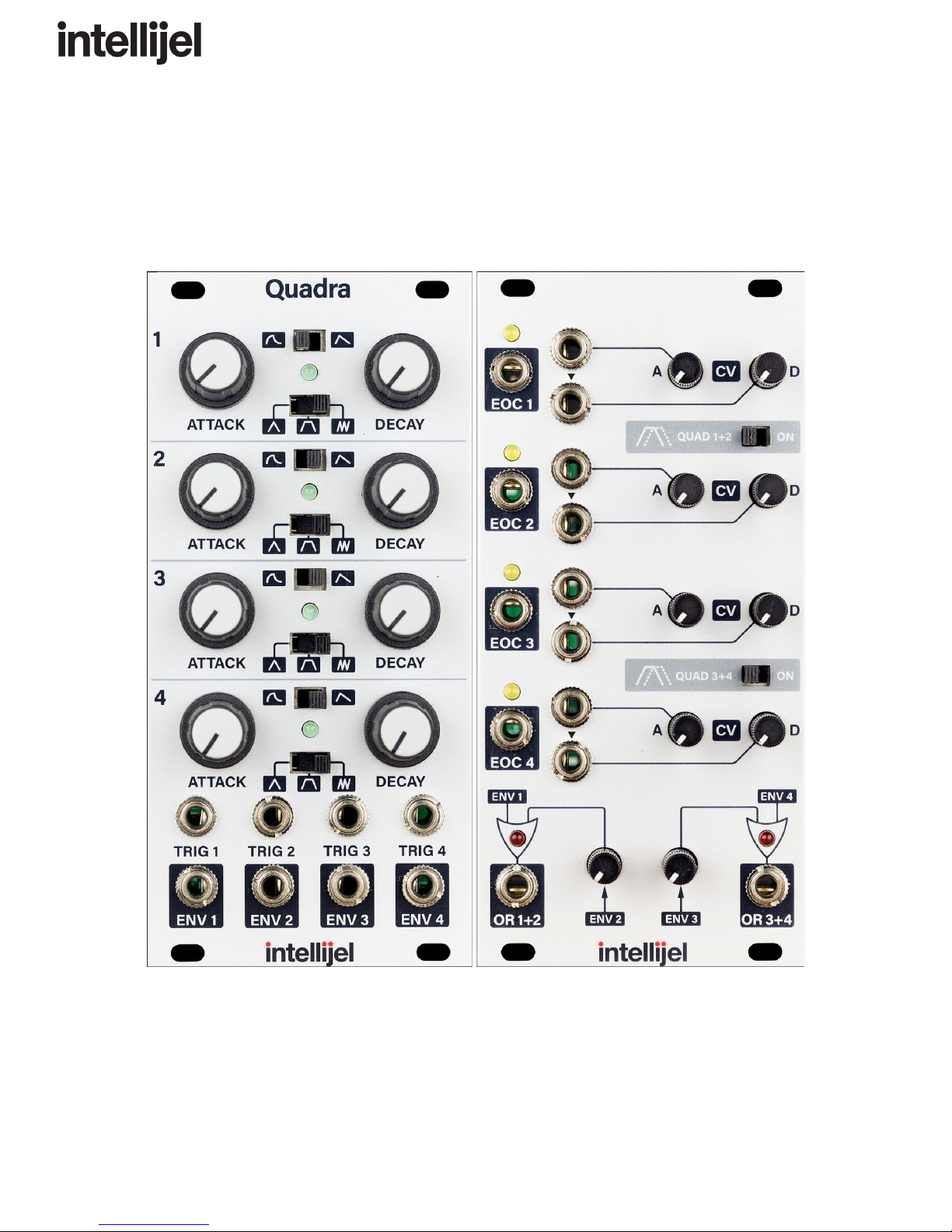
Quadra Front Panel
Controls
Inputs and Outputs
Expander Front Panel
Controls
Inputs and Outputs
Functions and Envelopes
Linear Versus Exponential Shapes
Quadrature Mode
ADSR Envelope Generation Using the OR Outs
Patch Examples
Technical Specifications
Page 1

Quadra Manual v1.00
Overview
The Intellijel Quadra and Expander modules comprise four parallel function generators (more
commonly referred to as “Envelope Generators”. The Quadra function generators have three
modes, AD (Attack, Decay), ASR (Attack, Sustain, Release) and Cycle (perpetually repeating
AR envelope or unipolar LFO). Each function can be configured to have a linear or exponential
curve and they feature a wide time base control from 0.5ms to over 30 seconds. The Expander
enhances the core functionality by allowing attenuated voltage control over Attack and Decay
for each function generator, a Quadrature mode, and an analog OR mixer for each function
generator pair.
This manual will cover both the Quadra and its optional Expander module.
Quadra Features
●Four function generators with Attack and Decay times ranging from from 0.5 milliseconds
to over 30 seconds.
●Three modes: AD (attack, decay), ASR (attack, sustain, release), Cycle (AD envelope
loops)
●Exponential and Linear envelope curves
Additional Expander Features
● Four End of Cycle pulse outputs corresponding to the four function generators.
● Voltage control of attack and decay (with attenuators) of all four envelopes
● Two analog OR (Also known as Peak Circuit) logic outputs that are normalled to the two
pairs of envelopes with attenuators.
● Special Quadrature modes.
Page 2

Quadra Manual v1.00
Installation
Intellijel Eurorack modules are designed to be used with a Eurorack-compatible case and power
supply.
Before Your Start
Before installing a new module in your case you must ensure your case’s power supply has
sufficient available capacity to power the module:
● Sum up the specified +12V current draw for all modules, including the new one. Do the
same for the -12 V and +5V current draw. The current draw will be specified in the
manufacturer's technical specifications for each module.
● Compare each of the sums to specifications for your case’s power supply.
● Only proceed with installation if none of the values exceeds the power supply’s
specifications. Otherwise you must remove modules to free up capacity or upgrade your
power supply.
You will also need to ensure you have enough free space (hp) as well as free power headers in
your case to fit the new module.
You can use a tool like ModularGrid to assist in your planning. Failure to adequately power your
modules may result in damage to your modules or power supply. If you are unsure, please
contact us before proceeding.
Installing Your Module
When installing or removing a module from your case always turn off the power to the case and
disconnect the power cable. Failure to do so may result in serious injury or equipment damage.
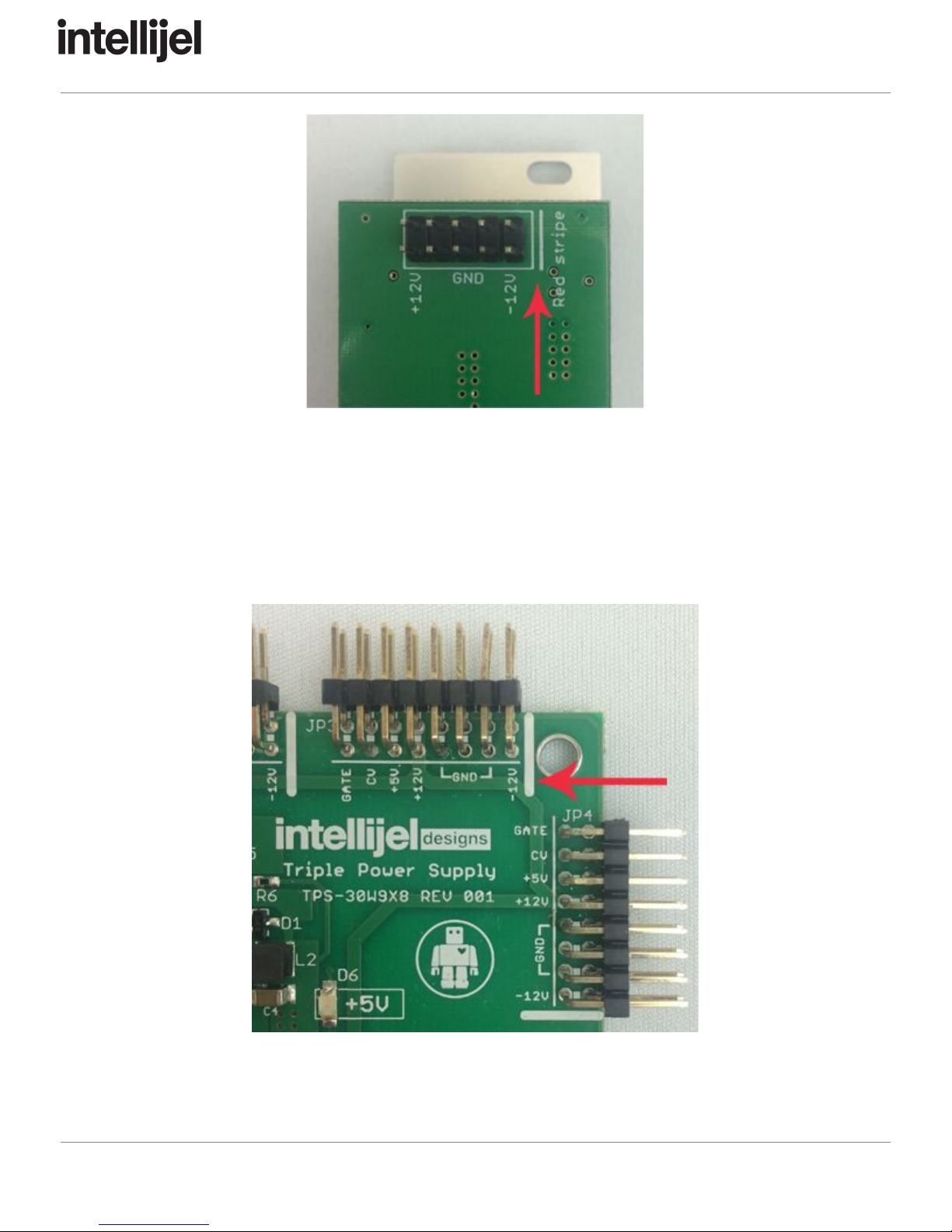
Ensure the 10-pin connector on the power cable is connected correctly to the module before
proceeding. The red stripe on the cable must line up with the -12V pins on the module’s power
connector. The pins are indicated with the label -12V, a white stripe next to the connector, the
words “red stripe”, or some combination of those indicators.
Page 3
Quadra Manual v1.00
Most modules will come with the cable already connected but it is good to double check the
orientation. Be aware that some modules may have headers that serve other purposes so
ensure the cable is connected to the right one.
The other end of the cable, with a 16-pin connector, connects to the power bus board of your
Eurorack case. Ensure the red stripe on the cable lines up with the -12V pins on the bus board.
On Intellijel power supplies the pins are labelled with the label “-12V” and a thick white stripe:
If you are using another manufacturer’s power supply, check their documentation for
instructions.
Page 4
Other manuals for Quadra
1
This manual suits for next models
1
Table of contents
Other Intellijel Music Equipment manuals


