Intellijel Pedal I/O 1U User manual

Pedal I/O 1U Manual
Pedal I/O 1U System
Effects Pedal Send/Return and High Impedance Instrument Input for Eurorack
Manual Revision: 2017.12.06

Pedal I/O 1U Manual
Table of Contents
Table of Contents
Overview
System
Features
Installation
Before Your Start
Powering Your Module
Connecting The Pedal I/O Jacks 1U Module
Connecting The Pedal I/O 7U Case Adapter
Front Panel (Pedal I/O 1U)
Controls
Inputs & Outputs
Front Panel (Pedal I/O Jacks 1U)
Inputs & Outputs
Technical Specifications
Page 1

Pedal I/O 1U Manual
Overview
Eurorack is a synthesist’s toy chest. Stompboxes are a guitarist’s toy chest. Each industry offers
a seemingly infinite variety of products that enable musicians to build systems unique to their
needs, and to create a signature sound. Each is also somewhat addictive. Rare is the musician
who doesn’t eventually need a larger toy chest to house the accumulated toys.
Fortunately for the budget conscious musician, Eurorack modules and stompboxes have always
existed in separate worlds — someone whose eurorack system consumes an entire wall in their
home is usually not the same person whose pedalboard now requires a dedicated roadie just to
transport it to the gig.
But those worlds have now collided. Thanks to the release of the Pedal I/O 1U system, Intellijel
has knocked down the barrier between eurorack and stompbox. This seemingly innocuous little
product is both a modular synthesist’s portal to stompbox nirvana, and a guitarist’s wormhole to
the sonic manipulations of eurorack modules.
The Pedal I/O 1U system enables the modular synthesist to interact with the impressive
assortment of delays, choruses, flangers, phasers, fuzz boxes, tremolos, wah-wahs, amp
simulators, compressors and pitch shifter pedals available to guitarists. Conversely, it also
grants guitarists access to the myriad filters, ring mods, wavefolders and — most importantly —
the near infinite CV modulation delights inherent in eurorack.
Page 2

Pedal I/O 1U Manual
System
A complete eurorack/stompbox solution requires the purchase of two components:
● A Pedal I/O 1U Module
The Pedal I/O 1U module houses all the
necessary gain and impedance-matching
circuitry, along with the ⅛” jacks required to
interface with eurorack modules. It also includes
the link cable for connecting one of the two ¼”
jack options outlined below.
● Either a Pedal I/O 7U Case Adapter, or a Pedal I/O Jacks 1U module.
Pedal I/O 7U Case Adapter
If you own an Intellijel 7U case (and if you wish to
use the case’s built-in ¼” jacks to connect the
guitar/stompbox) then you need the Pedal I/O
7U Case Adapter, which connects the Pedal I/O
1U module to the ¼” jacks. Since a 7U case has
two ¼” inputs and two ¼” outputs, you can
connect two Pedal I/O 1U modules to a single 7U
adapter.
Pedal I/O Jacks 1U Module
If you don’t own an Intellijel 7U case (or if you
prefer not to use its built-in ¼” jacks for pedal
interface purposes), then you need to purchase a
Pedal I/O Jacks 1U module, which connects
behind-the-panel to the Pedal Interface 1U
module, and provides a pair of ¼” in/out jacks for
connecting guitars or stompboxes.
Page 3

Pedal I/O 1U Manual
Features
● Signals arriving at the Pedal I/O System through the RETURN jack (or from a 7U case’s
IN jack if using the Pedal I/O 7U Case Adapter) pass through a Class A triode emulator,
allowing for some tube-like overdrive at high gain setting.
● The Pedal I/O is more than just a simple level shifter — it’s also an impedance converter,
which provides proper drive and loading for any FX pedals or instruments you connect.
● Separate gain controls on both the SEND and RETURN. This enables you to adjust the
level of any audio being sent to the FX pedals as well as any audio coming back into the
modular. Not only does this allow you to optimize the signal-to-noise ratio, but by
significantly boosting the RETURN level, you can achieve some pleasingly overdriven
tones.
● Use the Pedal I/O’s RETURN circuit as a “direct box” for connecting any instrument.
● The high input impedance of the RETURN circuit allows it to be used as a piezo pickup
preamp for acoustic instruments.
● Use Pedal I/O in the studio as an active “re-amping” device to play pre-recorded tracks
back through guitar amplifiers or pedals.
● All inputs are protected for minimum RF interference.
● Low MIX output impedance for driving long cables, lower noise, and minimum
interference from outside sources.
Page 4

Pedal I/O 1U Manual
Installation
Intellijel Eurorack modules are designed to be used with a Eurorack-compatible case and power
supply.
Before Your Start
Before installing a new module in your case you must ensure your case’s power supply has
sufficient available capacity to power the module:
● Sum up the specified +12V current draw for all modules, including the new one. Do the
same for the -12 V and +5V current draw. The current draw will be specified in the
manufacturer's technical specifications for each module.
● Compare each of the sums to specifications for your case’s power supply.
● Only proceed with installation if none of the values exceeds the power supply’s
specifications. Otherwise you must remove modules to free up capacity or upgrade your
power supply.
You will also need to ensure you have enough free space (hp) as well as free power headers in
your case to fit the new module.
You can use a tool like ModularGrid to assist in your planning. Failure to adequately power your
modules may result in damage to your modules or power supply. If you are unsure, please
contact us before proceeding.
Powering Your Module
When installing or removing a module from your case always turn off the power to the case and
disconnect the power cable. Failure to do so may result in serious injury or equipment damage.
Ensure the 10-pin connector on the power cable is connected correctly to the module before
proceeding. The red stripe on the cable must line up with the -12V pins on the module’s power
connector. The pins are indicated with the label -12V, a white stripe next to the connector, the
words “red stripe”, or some combination of those indicators.
Page 5

Pedal I/O 1U Manual
Most modules will come with the cable already connected but it is good to double check the
orientation. Be aware that some modules may have headers that serve other purposes so
ensure the cable is connected to the right one.
The other end of the cable, with a 16-pin connector, connects to the power bus board of your
Eurorack case. Ensure the red stripe on the cable lines up with the -12V pins on the bus board.
On Intellijel power supplies the pins are labelled with the label “-12V” and a thick white stripe:
Page 6
Pedal I/O 1U Manual
If you are using another manufacturer’s power supply, check their documentation for
instructions.
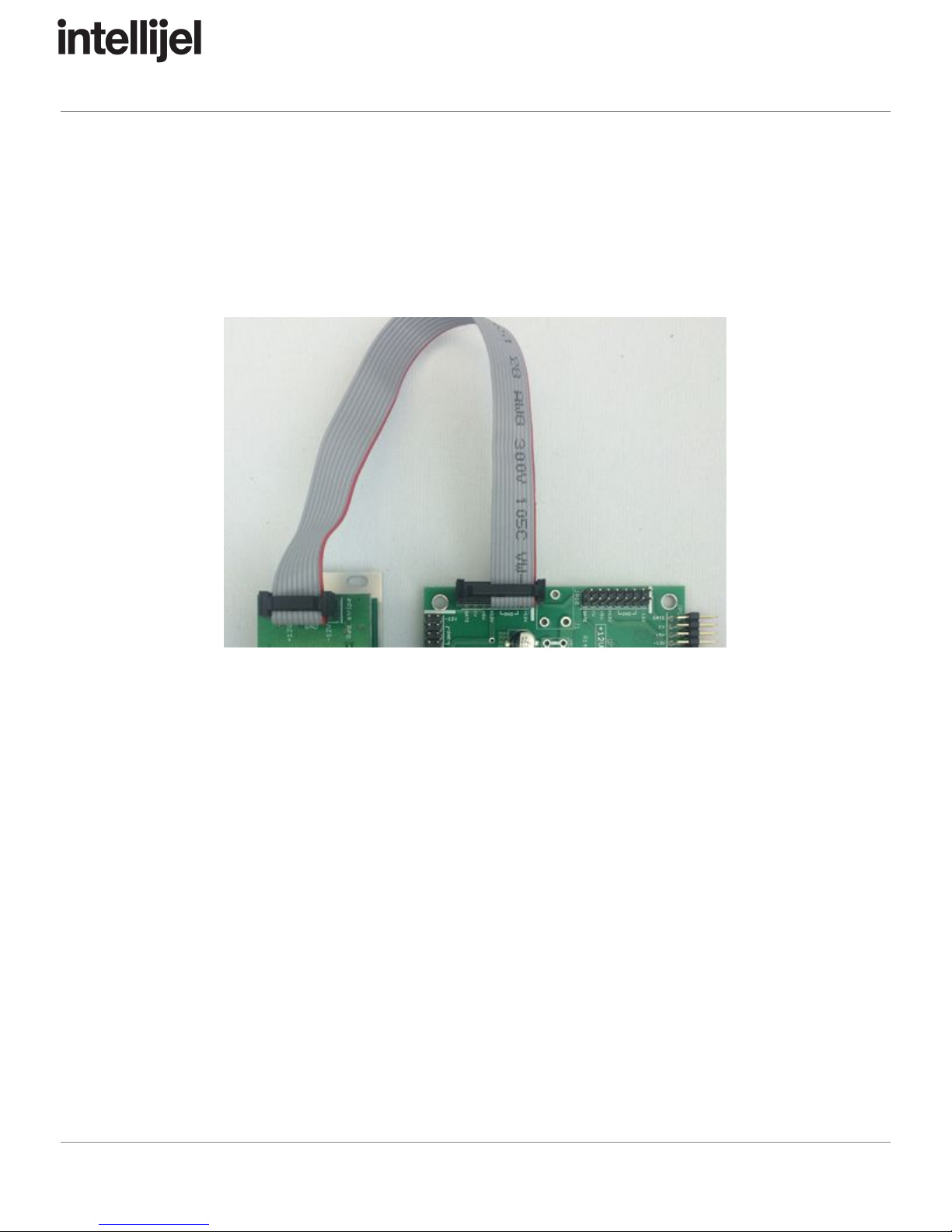
Once connected, the cabling between a module and power supply should resemble the picture
below:
Before reconnecting power and turning on your modular system, double check that the ribbon
cable is fully seated on both ends and that all the pins are correctly aligned. If the pins are
misaligned in any direction or the ribbon is backwards you can cause damage to your module,
power supply, or other modules.
After you have confirmed all the connections, you can reconnect the power cable and turn on
your modular system. You should immediately check that all your modules have powered on
and are functioning correctly. If you notice any anomalies, turn your system off right away and
check your cabling again for mistakes.
Page 7

Pedal I/O 1U Manual
Connecting The Pedal I/O Jacks 1U Module
The main Pedal I/O
module ships with a 3-wire link cable. Connect one end of this cable to the
Pedal I/O
module and the other end to either the Pedal I/O Jacks
module or the Pedal
I/O
7U
Case
Adapter
(one of which is needed to connect your external pedal’s ¼” jacks to your
eurorack modular).
If you purchased
the Pedal I/O Jacks
modules, simply
connect it to the
Pedal I/O
module
with the link cable
as shown to the
right.
The connectors are
keyed, so you can
orient them only
one way —
ensuring that you
can’t connect the
cable backwards. The Pedal I/O Jacks
does not require power, and the link cable is long
enough that the two module don’t have to be installed side-by-side if you don’t wish.
NOTE:
Never
use
the
3-wire
link
cable
to
connect
a
Pedal
I/O
module
to
an
Intellijel
Mixup
module.
Although
both
modules
use
this
same
cable/connector
—
they
serve
different
purposes
and
carry
different
signals.
Page 8
Pedal I/O 1U Manual
Connecting The Pedal I/O 7U Case Adapter
The main Pedal I/O
module ships with a 3-wire link cable. Use this to connect the Pedal I/O
module to either the Pedal I/O Jacks
module or the Pedal
I/O
7U
Case
Adapter
(one of which is
needed to connect your external pedal’s ¼” jacks to your eurorack modular).
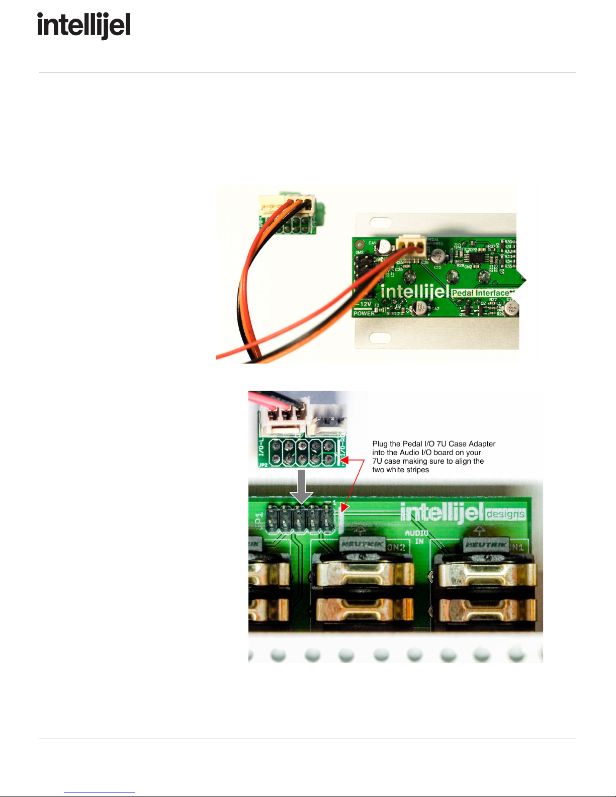
If you purchased the
Pedal I/O 7U
Case
Adapter
, simply connect it
to the Pedal I/O
module
with the link cable as
shown to the right. Note
that you can connect two
Pedal I/O
modules to a
single Pedal I/O 7U
Case
Adapter
(since there is a
pair if ¼” I/O jacks on the
7U case).
Next, plug the Pedal I/O 7U
Case
Adapter
into the your case’s
built-in Audio I/O
board, making
sure to align the white lines on
the two boards:
Page 9

Pedal I/O 1U Manual
Front Panel (Pedal I/O 1U)
Controls
A. SEND LEVEL knob - Adjusts the level of the signal arriving at the Pedal I/O’s IN jack
before it’s sent out of your modular and into your FX pedals (by way of either the ¼”
SEND jack on the Pedal I/O Jacks, or a ¼” OUT on a 7U case fitted with the
Pedal I/O 7U case adapter).
B. RETURN LEVEL knob - Adjusts the signal level coming back into the modular from your
external effects pedals, or from an instrument plugged directly into either the ¼”
RETURN jack on the Pedal I/O Jacks, or a ¼” IN on a 7U case fitted with the
Pedal I/O 7U case adapter.
C. CLIP Indicator LED - This LED monitors the signal level coming back into the modular
from either your external effects pedals, or from a connected instrument input. It lights
slightly before clipping, giving you a bit of headroom before actual clipping occurs. This
lets you maximize levels by allowing the CLIP LED to light occasionally on the highest
peaks. But as with all things musical — use your ears as the deciding factor!
D. MIX (DRY/WET) knob - Determines the wet/dry balance of the signal sent to the
module’s MIX output. Fully counterclockwise, only the DRY (unprocessed) signal is
heard in the MIX. Fully clockwise, only the WET (processed) signal is heard in the MIX.
At the noon position, equal amounts of WET and DRY appear in the MIX.
NOTE:
Not
every
pedal
is
designed
to
have
its
input
signal
mixed
in
with
its
output.
Some
(for
example,
phase
shifters)
may
return
a
signal
that
is
out
of
phase
with
the
original
audio,
so
balancing
the
Wet
&
Dry
levels
could
result
in
phase
cancellation.
In
such
cases,
you’ll
probably
want
to
set
the
MIX
knob
to
maximum
wetness.
Page 10

Pedal I/O 1U Manual
Inputs & Outputs
1. IN - Connect the audio signal you want processed by your external pedals to the IN jack.
Modular-level audio arriving at this jack is converted to instrument-level audio and
impedance-matched before it’s sent to either the Pedal I/O Jacks’ SEND jack or to one
of the 7U case’s ¼” OUT jacks (if fit with a Pedal I/O 7U Case Adapter).
2. MIX - Any audio that’s returned from your FX pedals is converted back to modular-level
and impedance-matched prior to appearing here at the MIX jack. If you plug a guitar or
other instrument into the Pedal I/O Jacks’ RETURN jack (or into one of the 7U case’s ¼”
IN jacks if fit with a Pedal I/O 7U Case Adapter), then the modular-level and
impedance-matched signal from that instrument appears at the MIX jack.
Page 11
Pedal I/O 1U Manual
Front Panel (Pedal I/O Jacks 1U)
Inputs & Outputs
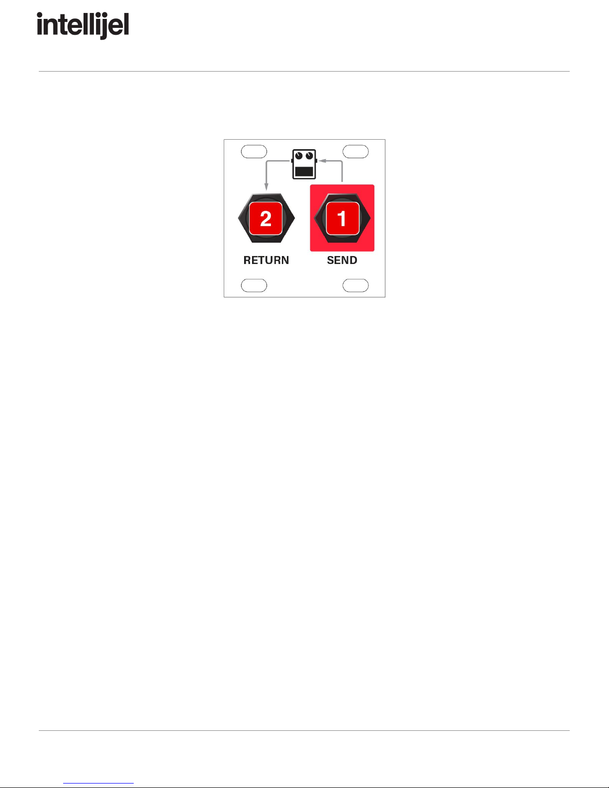
1. SEND - Connect a ¼” instrument cable from the SEND jack to the input of your external
FX pedal. The audio coming out the SEND jack is an instrument-level &
impedance-matched version of the modular-level audio signal you connected to the
Pedal I/O
module’s IN jack.
NOTE:
This
is
an
unbalanced
TS
cable
(standard
for
guitars
and
FX
pedals),
though
you
can
use
TRS
cables
—
you
just
won’t
get
any
benefit
from
doing
so.
2. RETURN - Connect a ¼” instrument cable from the output of your external FX pedal to
the RETURN jack on this module. The audio arriving at this jack is impedance-matched
and converted to modular-level by the Pedal I/O
module, where it’s then made available
at that module’s MIX jack.
You can also plug a guitar or other instrument directly into the RETURN jack and
process it with your modular synth. This is a high impedance input, allowing the
Pedal I/O system to act as a piezo pickup preamp for acoustic instruments. Audio
arriving at the RETURN jack passes through a Class A triode emulator (enabling
anything from clean to tube-like distortion) and an impedance converter and level shifter
to insure full integration in a modular synth environment.
NOTE:
This
is
an
unbalanced
TS
cable
(standard
for
guitars
and
FX
pedals),
though
you
can
use
TRS
cables
—
you
just
won’t
get
any
benefit
from
doing
so.
Page 12

Pedal I/O 1U Manual
Technical Specifications
Pedal I/O IN jack:
● Input level = 0 dBV nominal, +17 dBV max
● Input impedance = 60 KΩ
● Gain = -30 dB to -20 dB
● RF filter protected
Pedal I/O Jack SEND (or 7U Case Adapter OUT):
● Output level = -20 dBV to -30 dbV nominal based on Send Level
● Output impedance = 12 KΩ to simulate the impedance of magnetic guitar pickup
Pedal I/O Jack RETURN (or 7U Case Adapter IN):
● Input level = -20 dBV to -30 dBV nominal based on Return Level
● Input impedance = 1 MegΩ
● Return Gain = fully off to +30 dB
● RF filter protected
Pedal I/O MIX jack:
● Output level = 0 dBV nominal, +17dB max
● Output impedance = 100Ω
● Frequency response is 20Hz to 22KHz
● THD = 0.002% to 0.085% at Vin = 0dBV to +17dBV
(Pedal In to Pedal Out, Mix = effect, Return Level = min, Send Level = max)
THD = 0.04% to 4.0% at Vin = 0dBV to +17dBV
(Pedal In to Pedal Out, Mix = effect, Return Level = max, Send Level = max)
Pedal I/O Width
Pedal I/O Jacks Width
16 hp
8 hp
Pedal I/O Maximum Depth
Pedal I/O Jacks Depth
29 mm
44 mm
Current Draw
10 mA @ +12V
10 mA @ -12V
Page 13
Other manuals for Pedal I/O 1U
1
This manual suits for next models
1
Table of contents
Other Intellijel Music Pedal manuals


