Intellijel Audio I/O 1U User manual

Audio I/O 1U Manual
Audio I/O 1U System
Dual Balanced Line Audio Input and Balanced Line Audio Output
Manual Revision: 2018.02.07

Audio I/O 1U Manual
Table of Contents
Table of Contents
Overview
Features
System
Installation
Before Your Start
Powering Your Module
Connecting To The Audio I/O Jacks 1U Module
Connecting the TRS Jacks on the 7U Case
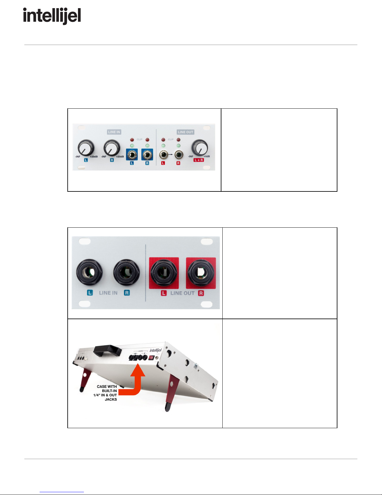
Front Panel (Audio I/O 1U)
Controls
Inputs & Outputs
Front Panel (Audio I/O Jacks 1U)
Inputs & Outputs
Technical Specifications
Page 1

Audio I/O 1U Manual
Overview
Use the Audio I/O 1U system to connect Eurorack modular-level signals to the balanced line
level (+4 dBu) signals used by professional audio gear. With this system, you can send audio to
and return audio from external FX units; patch in external line-level instruments like synths and
drum machines, output your modular audio to DAW; and much more.
The Audio I/O 1U system comprises two halves: an Audio I/O 1U module (for connecting to your
modular gear), and either an Audio I/O Jacks module or a 7U case with built-in ¼” audio jacks
(for connecting to your external studio gear).
Features
● 2 x Balanced TRS 1/4″ to Eurorack modular level input paths
● 2 x Eurorack modular level signals to Balanced TRS 1/4″ output paths
● 4 x two-stage LED VU meter to monitor all inputs and outputs simultaneously
● Uses high quality THATCorp balanced line drivers and receiver ICs.
● Input path has up to 20 dB of gain which allows you to patch in low level consumer level
signals and boost them. 0 dB = 10 Vpp (nominal Eurorack level)
● Output path steps a nominal Eurorack level (10 Vpp) down to +4 dBu with up to +6 dB
gain.
● The Audio I/O 1U module connects to the Audio I/O JACKS module via the included
ribbon cable. The same ribbon cable can be used to connect to the rear-mounted audio
jacks of the 7U performance cases.
Page 2
Audio I/O 1U Manual
System
A complete eurorack Audio I/O solution requires the purchase of two components:
● An Audio I/O 1U module
The Audio I/O 1U module houses
all the necessary line drivers,
VU meters and gain control
circuitry, along with the ⅛” jacks
required to interface with eurorack
modules. It also includes the ribbon
cable for connecting to either the
Audio I/O Jacks 1U module or an
Intellijel 7U case as outlined below.
● Either an Audio I/O Jacks 1U module or an Intellijel 7U Case with built-in ¼” TRS audio
jacks.
Audio I/O Jacks 1U Module
If you don’t own an Intellijel 7U
case, then you need to purchase
an Audio I/O Jacks 1U module,
which connects via ribbon cable to
the Audio I/O 1U module to
provide ¼” TRS in/out jacks for
interfacing with studio gear.
Pedal I/O 7U Case Adapter
If you own an Intellijel 7U case,
then you can connect the
Audio I/O 1U module directly to
the case using the ribbon cable
included with the Audio I/O 1U
module.
Page 3

Audio I/O 1U Manual
Installation
Intellijel Eurorack modules are designed to be used with a Eurorack-compatible case and power
supply.
Before Your Start
Before installing a new module in your case you must ensure your case’s power supply has
sufficient available capacity to power the module:
● Sum up the specified +12V current draw for all modules, including the new one. Do the
same for the -12 V and +5V current draw. The current draw will be specified in the
manufacturer's technical specifications for each module.
● Compare each of the sums to specifications for your case’s power supply.
● Only proceed with installation if none of the values exceeds the power supply’s
specifications. Otherwise you must remove modules to free up capacity or upgrade your
power supply.
You will also need to ensure you have enough free space (hp) as well as free power headers in
your case to fit the new module.
You can use a tool like ModularGrid to assist in your planning. Failure to adequately power your
modules may result in damage to your modules or power supply. If you are unsure, please
contact us before proceeding.
Powering Your Module
When installing or removing a module from your case always turn off the power to the case and
disconnect the power cable. Failure to do so may result in serious injury or equipment damage.
Ensure the 10-pin connector on the power cable is connected correctly to the module before
proceeding. The red stripe on the cable must line up with the -12V pins on the module’s power
connector. The pins are indicated with the label -12V, a white stripe next to the connector, the
words “red stripe”, or some combination of those indicators.
Page 4

Audio I/O 1U Manual
Most modules will come with the cable already connected but it is good to double check the
orientation. Be aware that some modules may have headers that serve other purposes so
ensure the cable is connected to the right one.
The other end of the cable, with a 16-pin connector, connects to the power bus board of your
Eurorack case. Ensure the red stripe on the cable lines up with the -12V pins on the bus board.
On Intellijel power supplies the pins are labelled with the label “-12V” and a thick white stripe:
Page 5
Audio I/O 1U Manual
If you are using another manufacturer’s power supply, check their documentation for
instructions.
Once connected, the cabling between a module and power supply should resemble the picture
below:
Before reconnecting power and turning on your modular system, double check that the ribbon
cable is fully seated on both ends and that all the pins are correctly aligned. If the pins are
misaligned in any direction or the ribbon is backwards you can cause damage to your module,
power supply, or other modules.
After you have confirmed all the connections, you can reconnect the power cable and turn on
your modular system. You should immediately check that all your modules have powered on
and are functioning correctly. If you notice any anomalies, turn your system off right away and
check your cabling again for mistakes.
Page 6

Audio I/O 1U Manual
Connecting To The Audio I/O Jacks 1U Module
The main Audio I/O 1U
module ships with a ribbon cable for connecting to a set of ¼” TRS
audio jacks — either those built-in to the Intellijel 7U case
or those contained within the
separately available Audio I/O Jacks 1U
module. To connect the Audio I/O 1U
module to an
Audio I/O Jacks 1U
module:
1. Make note of the small triangle
icon pointing to a pin on each
circuit board.
2. Plug one end of the ribbon
cable into the Audio I/O 1U
module such that the red stripe
aligns with the pair of pins
indicated by the triangle.
3. Plug the other end into the Audio I/O Jacks 1U
module, again making sure to align the
red strip with the pair of pins indicated by the triangle.
IMPORTANT: Do not connect this jack to a power supply.
Page 7

Audio I/O 1U Manual
Connecting the TRS Jacks on the 7U Case
The main Audio I/O 1U
module ships with a ribbon cable for connecting to a set of ¼” TRS
audio jacks — either those built-in to the Intellijel 7U case
or those contained within the
separately available Audio I/O Jacks 1U
module. To connect the Audio I/O 1U
module to an
Intellijel 7U case
:
4. Make note of the small
triangle icon pointing to a
pin on each circuit board.
5. Plug one end of the ribbon
cable into the Audio I/O 1U
module such that the red
stripe aligns with the pair of
pins indicated by the
triangle.
6. Plug the other end into the audio jacks circuit board that’s mounted inside the 7U case
and contains the ¼” jacks, again making sure to align the red strip with the pair of pins
indicated by the triangle.
IMPORTANT: Do not connect this jack to a power supply.
NOTE: Do not try to connect the Audio I/O 1U to the MIDI circuit board, which is
located at the opposite end of the 7U case.
Page 8

Audio I/O 1U Manual
Front Panel (Audio I/O 1U)
Controls
A. LINE IN GAIN (L) knob - Adjusts the level of the signal coming into the modular via
either the 7U Case’s
left ¼” input jack or the Audio I/O Jack 1U
module’s left ¼” input
jack.
This knob has up to 20 dB of gain, which allows you to patch in low consumer level
signals and boost them. 0 dB = 10V p-p (nominal Eurorack level).
B. LINE IN GAIN (R) knob - Adjusts the level of the signal coming into the modular via
either the 7U Case’s
right ¼” input jack or the Audio I/O Jack 1U
module’s right ¼” input
jack.
This knob has up to 20 dB of gain, which allows you to patch in low consumer level
signals and boost them. 0 dB = 10V p-p (nominal Eurorack level).
C. LINE OUT GAIN (L+R) knob - Adjusts the level of the signal going out of the modular
via either the 7U Case’s
left/right ¼” output jacks or the Audio I/O Jack 1U
module’s
left/right ¼” output jack.
This knob steps a nominal Eurorack level (10V p-p) down to +4 dBu (with the knob
roughly at 12:00), but allows for up to +6 dB of gain.
D. INPUT VU LEDs - This pair of LEDs monitors the signal level coming into the modular
from an external source. The green LED lights around 300mV rms, and indicates the
presence of a healthy signal. The red LED indicates that the signal is clipping the input
and comes on at 9V peak (6.2V rms) with a 1kHz sine). If the red light comes on, you
need to back off on your input levels.
Page 9

Audio I/O 1U Manual
E. OUTPUT VU LEDs - This pair of LEDs monitors the signal level going out of your
modular. The green LED lights around 600mV rms (with a 1kHz sine), which indicates a
decent signal level is present. Red indicates that the signal is clipping the output and
comes out when the output is 6.2V rms. If the red light comes on, you need to back off
on your levels.
Inputs & Outputs
1. LINE IN (L) - The audio present at this jack is a eurorack-compatible (0 dB = 10V p-p)
version of the audio signal coming into the modular via either the 7U Case’s
left ¼” input
jack or the Audio I/O Jacks 1U’s
left ¼” input jack. The actual level present at this jack is
set by the corresponding LINE IN GAIN (L) knob, and you can monitor this level with the
INPUT VU LEDs immediately above it. This jack enables you to route external audio
signals to various eurorack modules for processing.
2. LINE IN (R) - The audio present at this jack is a eurorack-compatible (0 dB = 10V p-p)
version of the audio signal coming into the modular via either the 7U Case’s
right ¼”
input jack or the Audio I/O Jacks 1U’s
right ¼” input jack. The actual level present at this
jack is set by the corresponding LINE IN GAIN (R) knob, and you can monitor this level
with the INPUT VU LEDs immediately above it. This jack enables you to route external
audio signals to various eurorack modules for processing.
3. LINE OUT (L) - Any eurorack-level audio sent to this jack will be scaled down to
professional studio-standard +4 dBu levels and sent out of your modular via either the
7U Case’s
left ¼” output jack or the Audio I/O Jacks 1U
module’s left ¼” output jack.
This enables you to send eurorack audio directly into your mixer, DAW, or external
effects. You can adjust this level using the LINE OUT GAIN (L+R) knob, and you can
monitor the LEFT channel output level with the 2-stage OUTPUT VU LEDs immediately
above this jack.
NOTE: The
LINE OUT (L)
jack is normalled to the
LINE OUT (R)
jack, so if nothing is
connected to the
LINE OUT (R)
, then one signal will feed both of the ¼” output jacks
(either from the
7U Case, or from the
Audio I/O Jacks 1U module, whichever you’ve
connected).
4. LINE OUT (R) - Any eurorack-level audio sent to this jack will be scaled down to
professional studio-standard +4 dBu levels and sent out of your modular via either the
7U Case’s
right ¼” output jack or the Audio I/O Jacks 1U
module’s right ¼” output jack.
This enables you to send eurorack audio directly into your mixer, DAW, or external
effects. You can adjust this level using the LINE OUT GAIN (L+R) knob, and you can
monitor the RIGHT channel output level with the 2-stage OUTPUT VU LEDs
immediately above this jack.
Page 10

Audio I/O 1U Manual
Front Panel (Audio I/O Jacks 1U)
Inputs & Outputs
1. LINE IN (L) - Connect the output of any external pro-level audio source to this ¼” TRS
jack for processing within your eurorack modular. The signal present here will be
amplified to eurorack levels by the Audio I/O 1U
module and made available at that
module’s LINE IN (L) ⅛” jack.
NOTE: This is a balanced ¼” TRS jack, but the
Audio I/O 1U circuitry readily supports
the use of unbalanced TS cables, and it can boost instrument- and consumer-level
signals to eurorack levels.
2. LINE IN (R) - Connect the output of any external pro-level audio source to this ¼” TRS
jack for processing within your eurorack modular. The signal present here will be
amplified to eurorack levels by the Audio I/O 1U
module and made available at that
module’s LINE IN (R) ⅛” jack.
NOTE: This is a balanced ¼” TRS jack, but the
Audio I/O 1U circuitry readily supports
the use of unbalanced TS cables, and it can boost instrument- and consumer-level
signals to eurorack levels.
3. LINE OUT (L) - The scaled output of your Audio I/O 1U’s
LINE OUT (L) ⅛” jack appears
at this ¼” TRS jack for mixing with other studio-level gear or for recording in your DAW.
This output supports both professional, balanced +4 dBu equipment and consumer,
unbalanced -10 dbV level gear.
4. LINE OUT (R) - The scaled output of your Audio I/O 1U’s
LINE OUT (R) ⅛” jack appears
at this ¼” TRS jack for mixing with other studio-level gear or for recording in your DAW.
This output supports both professional, balanced +4 dBu equipment and consumer,
unbalanced -10 dbV level gear.
Page 11

Audio I/O 1U Manual
Technical Specifications
Audio I/O Width
Audio I/O Jacks Width
24 hp
16 hp
Audio I/O Maximum Depth
Audio I/O Jacks Maximum Depth
36 mm
38 mm
Audio I/O Current Draw
Audio I/O Jacks Current Draw
39 mA @ +12V | 28 mA @ -12V
0 mA (passive module)
Page 12
Other manuals for Audio I/O 1U
1
This manual suits for next models
2
Table of contents
Other Intellijel Stereo System manuals


