IntelliSense MWS Commercial Series User manual

Intellisense Systems, Inc. – 1 – Installation Guide
20600 Gramercy Place IG AWARE Flood-11-2019
Torrance, CA 90501-1821 Revision: A
(310) 320-1827
Micro Weather Station (MWS®)
User Guide
– Commercial Series
Intellisense Systems Inc.
Page 1
– Rev 02.25.21Micro Weather Station (MWS®) User Guide – Commercial Series
MICRO WEATHER STATION (MWS®) OVERVIEW
This guide serves as a comprehensive overview of the installation and operation of the Commercial Series of
Micro Weather Stations (MWS®) from Intellisense Systems. Features that are not included on certain models
will be noted in the charts, graphics, and installation instructions to follow.
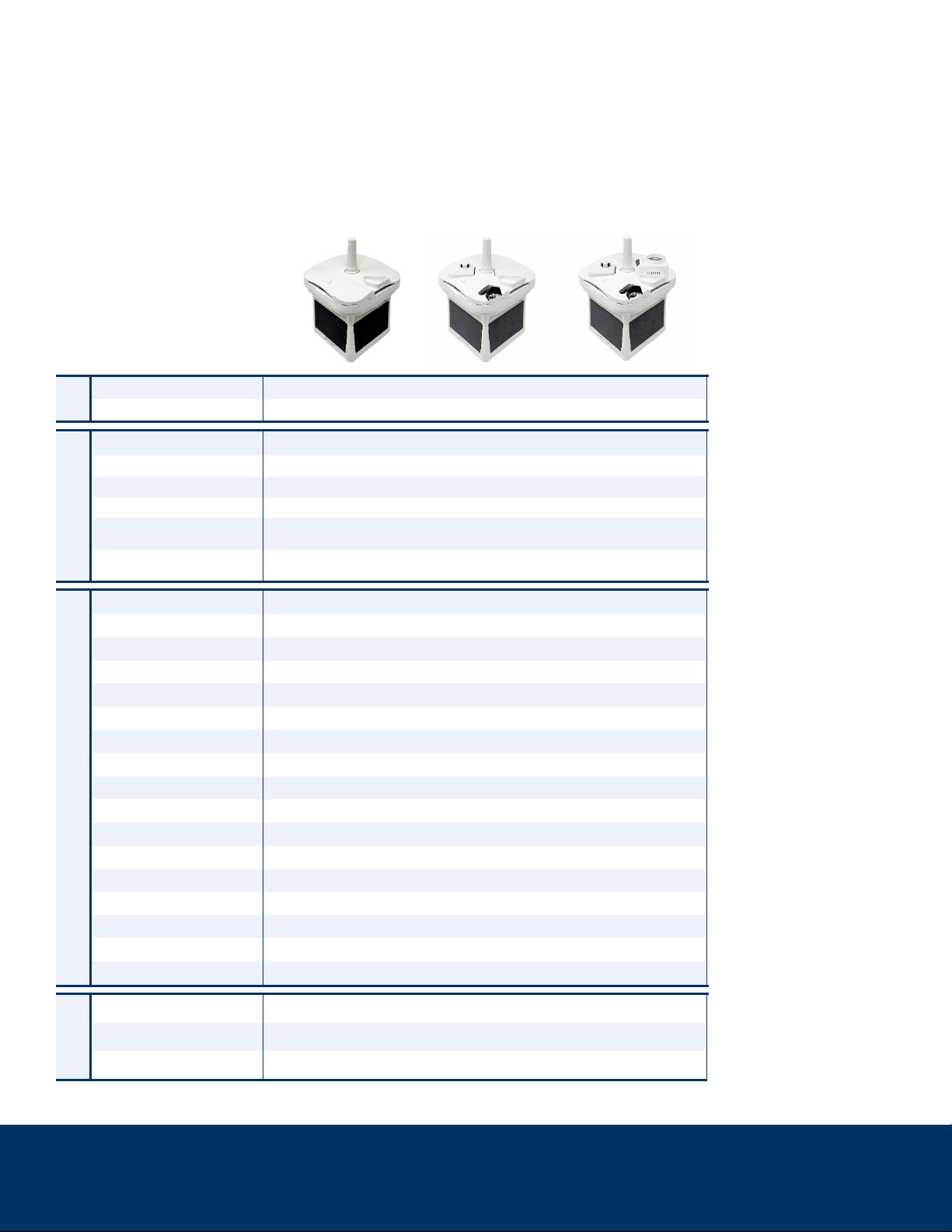
The MWS Commercial Series At-A-Glance
Series Name Commercial
Model No. C400 C500 C600
FEATURES
Colors Available:
White
•
•
•
Coyote Brown o
o
o
Integrated Solar Panels
•
•
•
Integrated NiCd
Battery Pack
• • •
Integrated Cloud-based
Data Processing
• • •
MEASUREMENTS & CAPABILITIES
Temperature • • •
Pressure (Barometric) • • •
Humidity • • •
Altimeter • • •
Wind Speed • • •
Wind Direction • • •
Angular Tilt • • •
Dust Accumulation — • •
Lightning Count • • •
Lightning Distance • • •
GPS • • •
Compass • • •
Precipitation Amount • • •
Present Weather — • •
Visibility — • •
360° Panoramic Camera — • •
Ceilometer — — •
COMM.
Cabled (RS-232 to USB) • • •
Cellular LTE-M • • •
Iridium SBD ooo
Table Key:
•= Standard
o= Optional
— = Not available

Intellisense Systems Inc.
Page 2
– Rev 02.25.21Micro Weather Station (MWS®) User Guide – Commercial Series
MWS Features
Environmental Parameters Measured and Calculated
The MWS measures the following environmental parameters using on-board sensors:
1. Air Temperature 11. Precipitation Type (C500 & C600 models only)
2. Relative Humidity 12. Precipitation Amount
3. Barometric Pressure 13. Lightning Frequency
4. Wind Speed 14. Lightning Distance
5. Peak Wind Speed 15. Compass Orientation
6. Wind Direction 16. Angular Tilt
7. Peak Wind Direction 17. Visibility (C500 & C600 models only)
8. GPS Latitude 18. Debris Accumulation (C500 & C600 models only)
9. GPS Longitude 19. Cloud Height (C600 models only)
10. GPS Elevation
These environmental parameters are determined using inputs from a combination of sensors and internal
data processing on the MWS:
1. Wind Chill 4. Altimeter Setting
2. Heat Index 5. Pressure Altitude
3. Dew Point 6. Density Altitude
Antenna for LTE-M or Iridium Comms.
360° Panoramic Camera
(C500/600 Models only)
Visibility Sensor
(C500/600 models only)
Wind, Temperature &
Humidity Sensors
(Inside Wind Gap)
Barometer, Compass,
Tip/Tilt, & Impact
Sensors (Inside)
Power Switch
Ceilometer
(C600 models only)
Precipitation Volume
Collector
Debris Accumulation Sensor
(C500/600 models only)
Solar Cells
Serial and Expansion Ports
(Behind)
Indicator Lights
NiCd Battery Pack
(Inside)
Intellisense Systems Inc.
Page 3
– Rev 02.25.21Micro Weather Station (MWS®) User Guide – Commercial Series
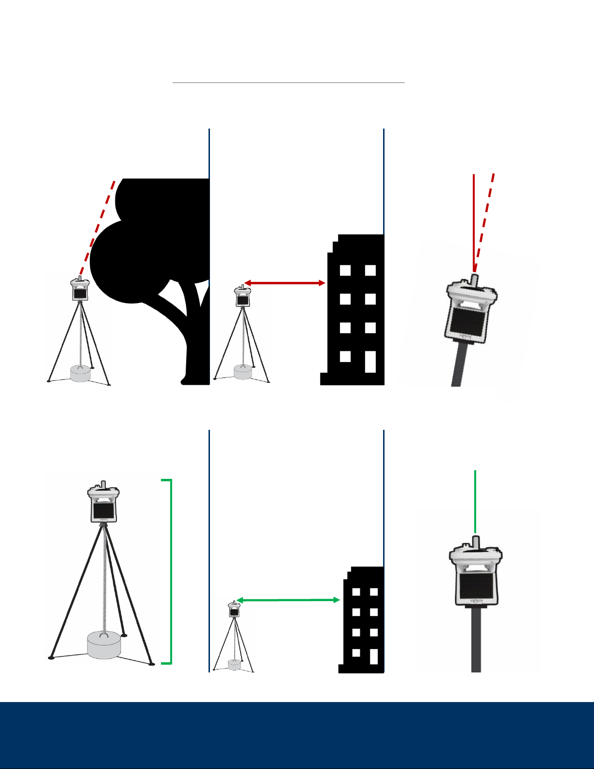
SITE SELECTION
Before installing your MWS, first determine the ideal location for your station. Consider these conditions to
ensure the most accurate collection of environmental data before installing your MWS.
DO NOT: DO NOT: DO NOT:
Install near any large objects
that obstruct the unit from
above
Place the unit within 30 ft of
any structures, trees, or
boulders taller than the MWS
Use a mounting solution that
may cause the unit to tilt more
than 10° off center
DO: DO: DO:
Mount the unit at least 3 ft or
higher off the ground or
surface (6 ft or higher is ideal)
Install the unit at least
30 ft away from any
structures, trees, or boulders
that are taller than the MWS
Use a strongly anchored
mounting point that will not
cause the unit to tilt
< 30 ft.
> 30 ft
6+ ft
> 10°
0°
Intellisense Systems Inc.
Page 4
– Rev 02.25.21Micro Weather Station (MWS®) User Guide – Commercial Series
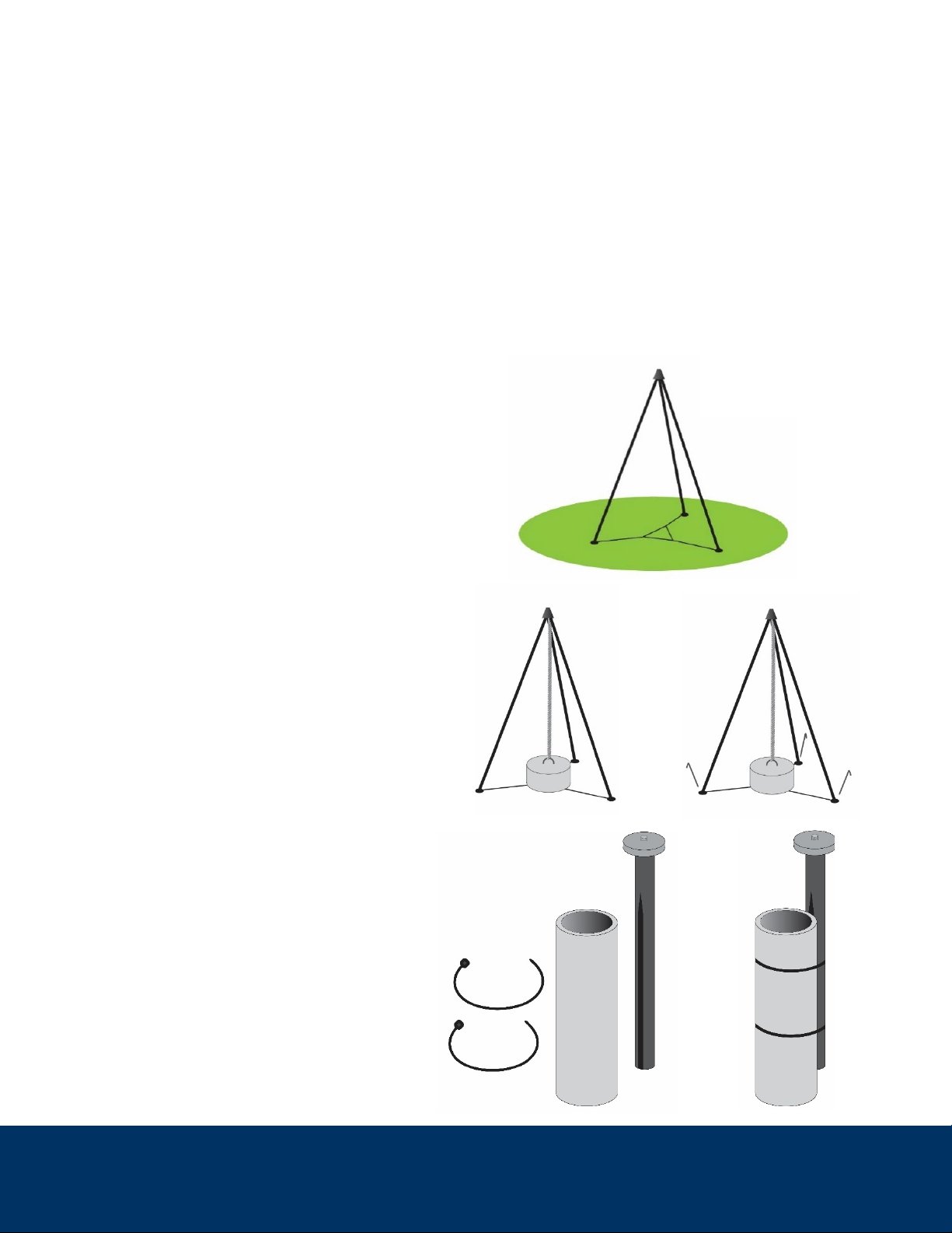
INSTALLATION INSTRUCTIONS
The MWS comes equipped with a standard ¼-20 threaded “camera” mount feature on its baseplate.
Intellisense recommends and offers two proven mounting solutions for the MWS to meet the needs of
lightweight and rugged portable deployment:
1. MWS Tripod – a low profile and fixed-height collapsible tripod with gimbal for leveling
2. MWS Pole Mount – a short, lightweight pole to temporarily affix to existing poles and structures
For all mounting solutions, the mount must be weighted down or rigidly affixed to a substrate to prevent the
dislodgement or accidental tipping of the system during high winds or other unintended incidents. Please
note: the mounting solution should be rigidly emplaced before the MWS is installed and turned on.
MWS Installation – Tripod
1. Place the tripod on level ground with a
clear view of the sky.
2. Secure the tripod to the ground with
an anchor or weight (25-50 lb weight
is recommended) attached to center
eyebolt.
3. If possible, secure the tripod legs to
the ground with stakes or by adding
weights on top of nylon webbing.
CAUTION: The MWS Tripod must be secured
to the ground with the center eyebolt before
attaching the MWS.
MWS Installation – Pole Mount
1. Place the grooved side of the pole
mount against a rigid, secure, and
vertically oriented pole.
2. Secure the pole mount using the
included zip ties.
1.
2.
2.
1.
3.

Intellisense Systems Inc.
Page 5
– Rev 02.25.21Micro Weather Station (MWS®) User Guide – Commercial Series
CONNECTIVITY AND REMOTE COMMANDS
To view the status of your station, send commands, or change the default settings, please visit:
www.quantimet.com
After powering on your weather station and a successful GPS sync, your data should be available and viewable
within ~30-60 minutes at the Quantimet website.
OPERATION
Powering on the MWS
Once the system is powered on, check the lights
beneath the cap (on the same side as the power
switch, pictured right) for these status indications:
3 lights: MWS is fully charged and will begin reporting automatically
2 lights: MWS is not fully charged but will begin reporting automatically
0–1 lights:Power is too low – the MWS requires solar or cabled charging
Flashing lights: Self-check failure
If the lights blink multiple times when the unit is first powered on, then there has been a self-check failure
and the unit will require maintenance by the manufacturer. If the lights do not illuminate, then the power is
too low and the unit will need to be charged. There are two options to charge the MWS:
1. Place the MWS in sunlight.
2. Connect the MWS to a power source using the MWS Data and Power Cable.
The unit will charge with the power switch in either the “ON” or “OFF” position. When charging outdoors,
the switch can remain in the “ON” position and the MWS will start reporting in the default mode once it has
enough power to operate.
NOTE: If the unit has been in service previously, visually inspect for dust or other debris build-up. This can be
removed from surfaces by gently wiping it with a soft cloth or towel soaked in water. For users of C6XX
Indicator Lights
Power Switch
Intellisense Systems Inc.
Page 6
– Rev 02.25.21Micro Weather Station (MWS®) User Guide – Commercial Series
models, ensure the lens and window of the ceilometer are clear by gently wiping them with a soft microfiber
lens cloth. To prevent moisture accumulation on the lens, gently wipe the provided Rain-X®wipe around the
lens in a circular motion to apply an even coat of the hydrophobic solution.
Special Battery Warning
In fast reporting mode or areas with little sun exposure and extreme cold temperatures, the MWS will need
to be charged to at least 5 V for extended full operations under these conditions. Please note that the
charging process could take up to 24 hours, so operation checks before installation are highly
recommended.
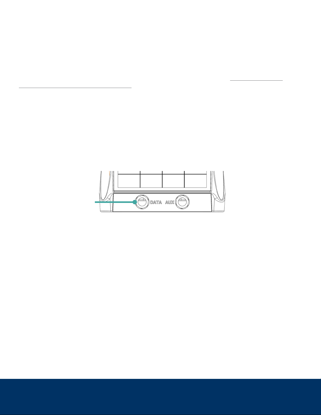
When your MWS is plugged in to hardline power with the “DATA” port (on the front of the unit, pictured
below), the system charges via a power and data cable over USB. As a result, the raw data voltage reading
is slightly higher than when it is unplugged. If the first report back from your MWS when not connected to
hardline power provides a low battery voltage (below 5 V), change the reporting mode to every 3 hours until
the battery is charged to over 5 V. If operating in limited sun exposure or there is a need to use the 5-minute
reporting mode, keep in 3-hour mode until the battery is charged to at least 5.5 V. Overall, monitoring the
MWS battery pack voltage over time and environmental changes will ensure system availability and limit
downtime due to low battery levels.
Cellular Signal Strength (Cellular Models Only)
Approximately 30 seconds after powering up, the unit will attempt to connect to the cellular network tied to
the factory-installed SIM card. After those 30 seconds, the LEDs will illuminate a second time to indicate the
signal strength at the current location.
Single LED flashing – No signal or SIM card not activated; the MWS will not report remotely without
cellular signal or activated SIM card.
Solid LEDs (one, two, or three) – The number of LEDs illuminated indicates the signal strength from
low to high. As long as a signal is indicated, the MWS will report data automatically.
Data Port for Hardline Power
Intellisense Systems Inc.
Page 7
– Rev 02.25.21Micro Weather Station (MWS®) User Guide – Commercial Series
Initial Operation
After the MWS is properly installed and powered on, the system reports its GPS location, which can take
15-30 minutes depending on satellite signal strength. The station will not transmit weather data without
a successful GPS sync, so please ensure that the unit is outdoors with a clear view of the sky to
guarantee a strong GPS signal. If the unit is indoors or unable to acquire a GPS signal, it will keep trying to
acquire satellites before reporting weather data. Make sure the unit is placed in an ideal location for
operation (see the “Site Selection” section above). Each time the unit is turned off and on, it will repeat the
15-30-minute GPS sync before reporting weather data.
Default Settings
When the MWS is first powered on, the default settings of operation are as follows:
1-hour reporting mode
Camera sends no images (C500/600 models only)
GPS latitude/longitude/elevation reported
Ceilometer set on auto (C600 models only)
The settings of your MWS can be changed using the Quantimet website and are stored on the unit even
after it is powered off.
Intellisense Systems Inc.
Page 8
– Rev 02.25.21Micro Weather Station (MWS®) User Guide – Commercial Series
REPORTING MODES
A summary of reporting modes based on model and measured parameters is outlined below:
The MWS’s weather reports are centered around discrete 10-second samples. These 10-second samples occur
at different intervals and are averaged differently depending on the set reporting mode. Details are as follows
for the different modes:
10-Second: Single 10-second sample reported continuously.
20-Second: Single 10-second sample reported every 20 seconds. (*This mode has a reduced sensitivity
to lightning when compared to the slower reporting modes.)
1-Minute: Single 10-second sample reported every minute.
5-Minute: This mode reports data in a similar fashion to FAA-based weather stations. 10-second
samples taken each 30 seconds and combined to report a 5-minute average. The last 4x 10-second
samples are averaged to also report last 2-minute wind average. Line power is required. If not line
powered, unit will default back to 1-hour mode if the battery depletes below 5.2 V. Max image
reporting speed of 1 set/hour.
20-Minute: 10x 10-second samples performed each minute in the last 10 minutes and averaged before
reporting every 20 minutes. Line power required if images requested, otherwise battery may deplete too
rapidly (C500/600 models only). Reports at 15, 35, and 55 minutes after the hour.
1-Hour (Default): 10x 10-second samples performed each minute in the last 10 minutesand averaged
before reporting every hour. Reports at 55 minutes after the hour.
3-Hour: 10x 10-second samples performed each minute in the last 10 minutes and averaged before
reporting every 3 hours. Reports every three hours at 55 minutes after the hour.

Intellisense Systems Inc.
Page 9
– Rev 02.25.21Micro Weather Station (MWS®) User Guide – Commercial Series
MAINTENANCE
Replacing Batteries
Occasionally, the battery pack inside the MWS may require replacement. To determine if the batteries need to
be replaced, check these guidelines below:
Charging the unit via USB cable and/or setting the unit in the sun for at least 24 hours will not charge
battery to > 5 V
MWS unable to maintain standard reporting mode due to low power
Operational situation does not permit time for in-system self-charging
Flashing LED indicator lights identify a Self-Check failure.
If the above four criteria are met, the battery likely requires replacement. To replace the battery pack, please
follow the steps below:
1. Flip the MWS over so that bottom side is facing upward (make sure the antenna and top-mounted
sensors are not damaged during this process)
2. Loosen the 4 thumb screws at each corner to remove bottom plate (screws should remain in the bottom
plate)
3. Pull on the tab to remove the battery from its enclosure
4. Gently disconnect the battery harness from battery pack
5. Connect the new battery pack to the harness
6. Reinstall the battery pack and screw the bottom plate back onto the unit
Sensor and System Notes
Power System: The power system of the MWS consists of nickel-cadmium (NiCd) batteries and crystalline solar
cells that provide state-of-the-art, reliable power storage and generation in extreme environments. The solar
power generation system on the MWS was designed to support hourly observations at a location between -50°
and +50° latitude, with 50% cloud cover, in winter conditions. By default, the MWS operates in hourly mode, but
at more extreme latitudes the MWS can be placed in 3-hour mode to reduce power consumption. Power is
considered marginal if the battery voltage ever falls below 5 V and should be conserved unless operations are
essential or critical.
Visibility Sensor (C500/600 models only): The visibility sensor works by sensing miniscule back-reflection from
the atmosphere, so it is required for the MWS to be in an open area outdoors. It is also important for the area
above the height of the MWS to be completely clear of obstructions. Using the sensor indoors will not yield
accurate environmental data, and the area surrounding the MWS must be cleared within a radius of 30 ft. For
the most accurate readings, it is also essential that debris (leaves, dust, spider webs, etc.) not cover any areas
of the sensor.

Intellisense Systems Inc.
Page 10
– Rev 02.25.21Micro Weather Station (MWS®) User Guide – Commercial Series
OPTIONAL SETTINGS AND ADVANCED FEATURES
Optional Settings
The optional settings control certain aspects of measurement timing and sampled parameters. They are stored
in memory and will stay in the last user-defined setting upon power-up.
GPS: GPS latitude and longitude can be enabled or disabled by the user. GPS is enabled from the
factory by default, which will allow you to determine the unit’s location when reporting. If the location is
not desired, it can be disabled. However, a GPS lock is still required upon powerup to obtain elevation
and to obtain the proper system time for reported weather readings. GPS coordinates are reset upon
each power cycle (via the physical power switch) and a re-lock is required upon each new power-up.
GPS will also attempt a re-sync approximately once every 10 days of continuous operation to
accomodate for station movement and to update the system clock.
Image Requests (C500/600 models only): A single image set can be requested or scheduled based on
system time (with hourly images being the fastest). When hourly images are requested, they will always
send at 56 minutes after the hour. The default setting is no images.
Ceilometer (C600 models only): There are 3 ceilometer settings: “Disabled.” “Enabled,” and “Enabled
Always.” The “Enabled Always” command enables users to take 4 ceilometer readings (in 15-minute
intervals) regardless of what reporting mode the station is in, which may consume more power. The
“Enabled” setting changes the number of ceilometer readings depending on reporting mode. The default
setting is “Enabled.”
Raw Output Over Serial Connection
For advanced users or those using custom data processing
software, the station output can also be viewed over serial
USB connection in its raw format by plugging a MWS Power
and Data Cable into the “DATA” port on the unit and plugging
the receiving end into a standard USB Type-A port on your
PC. The station will output over serial automatically at each
sample time as defined in the reporting descriptions above.
Output can be viewed on X-CTU or a similar serial terminal
software with the settings shown below and COM port that
coincides with the cable input. An example is pictured right:

Intellisense Systems Inc.
Page 11
– Rev 02.25.21Micro Weather Station (MWS®) User Guide – Commercial Series
A sample output packet viewed over RS-232 serial connection is shown below:
@I:356726109932152
@0AX
N:104:2/10
B:5.55:2:000000:78:5:VM
T:20/04/29,23:27:13
LA:34.99414
LO:-108.33632
EL:68:D
OR:88:3:257
TA:22.4
BA:1006.50:2995
RH:73
WI:4:357
GU:5:357
LD:?:0:--
CL:1KZ0F:0:?:?:?
PW:0.00:299:?:--:83:207:200
VI:6.2
XA:22.1:22.4:22.2:02
XD:9:9:18:17:26.6
The meaning of each output parameter is defined in the table below:
Tag
Name
Description
Example
@I
IMEI
Station Modem IMEI Number
@I:356726109932152
@0
Type
Message type and version
@0ab
N
Message
number
1) Rotating message number 0-255; rotates back to
16 so a number below 16 means new start
2) Sample cycle number / max number of cycles
N:255:10/10
B
Battery level
1) Battery level (Volts to 2 decimals)
2)
Operating mode
3) Auto-imaging hour setting (6-character
hexadecimal representing 24 bits, which represent
each hour in the 24 hour system; bit 0 = hour 0, bit 1
= hour 1...and bit 23 = hour 23. A bit is set if the hour
it represents is set for auto image capture)
4) MWS configuration
5) Days of operation count (2-3 digits typical)
6) Command key (2 upper/lower case alphabet
characters)
B:5.43:1:000000:6F:123:qr
T
Time
GPS UTC time YY/MM/DD,HH:MM:SS or with a
leading '-' if no GPS sync
T:16/02/26,20:10:45
LA
Latitude
GPS latitude (decimal degrees to 5 decimals) or ? if
no reading or disabled
LA:30.00900
LO
Longitude
GPS longitude (decimal degrees to 5 decimals) or ? if
no reading or disabled
LO:-85.95787

Intellisense Systems Inc.
Page 12
– Rev 02.25.21Micro Weather Station (MWS®) User Guide – Commercial Series
Tag
Name
Description
Example
EL
Elevation
1) GPS elevation (meters) or ? if no GPS reading
2) GPS VDOP (measure of vertical estimation
quality) divided into 0.2 increments over 1.0
converted to a-z, '-' if the elevation was set by the
user, or ? if no GPS reading
EL:1840:c
OR
Orientation
1) Compass orientation from magnetic north
(degress)
2) Tip from vertical (degrees)
3) Direction of tilt (degrees)
C:339:2:119
TA
Temperatur
e ambient
Ambient air temperature (degrees C to 1 decimal)
TA:29.1
BA
Barometric
pressure
1) Pressure (millibars to 2 decimals)
2) Altimeter setting (inHg x 100) if GPS active
BA:1008.19:2985
RH
Relative
humidity
Relative Humidity 0-99 (percent), or ? if not present
RH:25
WI
Wind speed
& direction
1) Average wind speed (knots)
2) Direction (degrees)
WI:2:225
GU
Peak wind &
direction
1) Peak wind speed (knots)
2) Direction (degrees)
GU:3:240
LD
Lightning
distance
1) Lightning distance (nautical miles to 1 decimal) or
? if no detections
2) Number of 5-minute detection periods with strikes
detected
3) Lightning event timestamps
Character 1: First event detected during 5-minute
intervals of GPS time converted to a-l.
Character 2: Last event detected during 5-minute
intervals of GPS time converted to a-l.
LD:1.0:4:cf
CL
Cloud height
1) Character 1: Ceilometer status 'a' if operating and
no detections, 1-4 if detection by method 1-4, '-' if
disabled, ? if not present or operating properly.
Character 2: Highest high clipping sample converted
to a-z from all sets of raw data. Character 3: Highest
low clipping sample converted to a-z from all sets of
raw data. Characters 4-5: Hex value of calculated
threshold.
2) Cloud height of ranging attempt 1 (meters)
3) Cloud height of ranging attempt 2 (meters)
4) Cloud height of ranging attempt 3 (meters)
5) Cloud height of ranging attempt 4 (meters)
Height ranging attempts report 0 if no cloud, or ? if
no or unsuccessful attempt
CL:1cp14:1000:1001:1002:100
3

Intellisense Systems Inc.
Page 13
– Rev 02.25.21Micro Weather Station (MWS®) User Guide – Commercial Series
Tag
Name
Description
Example
PW
Present
weather
1) Precipitation amount (in/hour to 2 decimals)
calculated from drops counted
2) Disdrometer peak 0-999
3) Spare field always displays '?'
4) Precipitation event timestamps (triggered by drop,
disdrometer, and moisture detection)
Character 1: First event detected during 5-minute
intervals of GPS time converted to a-l.
Character 2: Last event detected during 5-minute
intervals of GPS time converted to a-l.
5) Accumulation 0-99
6) Visibility millivolts
7) Visibility calibration value
PW:1.25:30:346:ek:99:115:100
VI
Visibility
Estimated visibility in miles (calculated from visibility
millivolts) to 1 decimal place at and above 2.0 miles,
2 decimal places below 2.0 miles.
VI:10.0
XA
Raw sensor
data
Raw sensor data
1) Temperature internal sensor (degrees C to 1
decimal)
2) Temperature external sensor (degrees C to 1
decimal) or ? if not present
3) Temperature from barometer (degrees C)
4) I2C errors
XA:35.0:29.9:35:02
XD
System
diagnostics
Phone: 310-320-1827
Email: Info@intellisenseinc.com
www.intellisenseinc.com
©2020 Intellisense Systems, Inc. All rights reserved. All other brands or names are the property of their respective holders.
UG-MWS-COMM-02-2021
This manual suits for next models
3
Table of contents
Popular Weather Station manuals by other brands

La Crosse Technology
La Crosse Technology Weather Direct WD-3308 owner's manual

Emos
Emos E8468 manual

Bushnell
Bushnell WEATHERFX 960900C quick start guide

WEATHER DIRECT
WEATHER DIRECT Weather Direct WD-3105 owner's manual

La Crosse Technology
La Crosse Technology WS-9016U instruction manual

Auriol
Auriol 114324-15-01 Operation and safety notes

Digoo
Digoo DG-TH2048 operating instructions

La Crosse Technology
La Crosse Technology 308-179OR manual

La Crosse Technology
La Crosse Technology C84428 instruction manual

Emos
Emos E0300 manual

HoMedics
HoMedics EnviraStation DWS-400 Instruction manual and warranty information

Honeywell
Honeywell TS805 Product brochure


