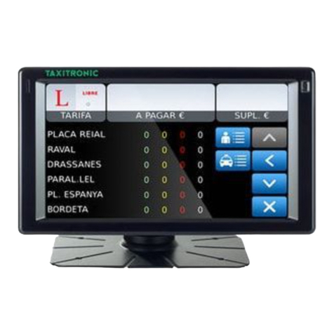
Interfacom TAXITRONIC TXD70 User manual

INSTALLATION MANUAL TXD70 INTERFACOM, S.A
TXD70_Install_Manual_en_023.doc 01/06/2016
INSTALLATION MANUAL
TAXITRONIC TXD70

INSTALLATION MANUAL TXD70 INTERFACOM, S.A
TXD70_Install_Manual_en_023.doc 2
INDEX
1. INTRODUCTION......................................................................................................... 4
2. MOUNTING................................................................................................................. 4
2.1. LOCATION OF MX70........................................................................................... 4
2.2. MOUNTING TXD70.............................................................................................. 4
2.2.1. LOCATION OF TXD70................................................................................................. 4
2.3. ELECTRICAL INSTALLATION............................................................................. 5
2.4. CHARACTERISTICS............................................................................................ 5
2.5. INSTALLATION RECOMMENDATIONS .............................................................. 6
2.6. FIRST TIME TURN ON ........................................................................................ 7
2.7. HARDWARE TEST .............................................................................................. 7
2.8. CONFIGURATION PARAMETERS...................................................................... 8
2.8.1. GPRS GSM .................................................................................................................. 9
2.8.2. RT PARAMS............................................................................................................... 10
2.8.3. TICKETS .................................................................................................................... 11
2.8.4. INSTALLATION.......................................................................................................... 12
2.8.5. TOUCHSCREEN CALIBRATION............................................................................... 13
2.8.6. RT PARAMS 2............................................................................................................ 13
2.8.7. SOFT UPDATE .......................................................................................................... 13
2.8.8. KERN UPDATE.......................................................................................................... 14
2.9. SWITCH TO NORMAL MODE ........................................................................... 14
3. TAXIMETER CONFIGURATION ............................................................................... 15
3.1. CONFIGURING IMPULSE SIGNAL.................................................................... 15
3.1.1. PULL-UP CONFIGURATION ..................................................................................... 17
3.1.2. CALCULATION OF THE K CONSTANT.................................................................... 18
3.1.3. ENTERING CONSTANT K......................................................................................... 19
3.2. PROGRAMMING PASSWORDS........................................................................ 19
3.3. SETTING THE CALENDAR - CLOCK................................................................ 19
3.4. RESET TOTALIZERS......................................................................................... 20
3.5. RECORD THE TARIFF ...................................................................................... 20
4. SEALING................................................................................................................... 21
4.1. MX70.................................................................................................................. 21
4.2. TXD70................................................................................................................ 21
5. MAINTENANCE......................................................................................................... 22
5.1. SWITCH TO INSTALLER MODE ....................................................................... 22
5.2. HARDWARE TEST ............................................................................................ 22
5.3. REMOTE TEST.................................................................................................. 23
5.4. REPAIRS............................................................................................................ 23
5.5. SOFTWARE UPDATE........................................................................................ 24
5.5.1. FROM NORMAL MODE............................................................................................. 24
5.5.2. FROM INSTALLER MODE......................................................................................... 24
6. NAVIGATOR LICENSE MANAGEMENT................................................................... 26
7. VERSION CONTROL................................................................................................ 29
ANNEX I: HARDWARE TEST SUMMARY TABLE ........................................................... 30

INSTALLATION MANUAL TXD70 INTERFACOM, S.A
TXD70_Install_Manual_en_023.doc 3
DRAWINGS LIST
Drawing 1 Bracket assembly
Drawing 2 TXD70 mounting on bracket
Drawing 3 Connectors
Drawing 4 Electrical installation drawing
Drawing 5 Installation with armored cables
Drawing 6 TXD70 Plastic sealing
Drawing 7 TXD70 Sealing stickers position
Drawing 8.1 TXD70 Cable seals
Drawing 8.2 MX70 Cable seals

INSTALLATION MANUAL TXD70 INTERFACOM, S.A
TXD70_Install_Manual_en_023.doc 4
1. INTRODUCTION
This document describes the installation and parameterization of TAXITRONIC TXD70.
2. MOUNTING
2.1. LOCATION OF MX70
TXD70 must be installed so that passengers can’t see or access it, but the verification
office must be able to access it. Seals and serial numbers must be easily visible and
accessible upon verification at a verification office.
Preferred positions are inside the glovebox, under the passenger seat or similar.
It is necessary that the identification sticker and the seals are easy to inspect. For this
reason it is necessary to take care of the orientation, with the stickers looking to the
outside. Cables can’t cover neither the identification sticker nor the seals.
2.2. MOUNTING TXD70
The installation of the TXD70 is to be done on its support (See drawings 1 and 2). The
design of the support allows for 3-dimension orientation of the TXD70, so it is adapted to
different dashboard designs.
The adhesive base is ready to be adhered to plastics, and supports the temperature
ranges inside a vehicle.
The connection is done by only one connector on the back of TXD70. The tools necessary
for installing TXD70 are:
Fixed hexagonal key nº 15.
Allen key nº2, minimum length of the shaft 100mm.
Allen key nº3.
Screwdriver with head H1
Isopropyl alcohol (If there are previous installation or tariff seals to be removed)
The orientation of TXD70 is fixed by screwing the two Allen screws on the sides (points B
and C on drawing 2). The central screw which touches directly on the support ball is not
used (see drawings 1 and 2)
The height of TXD70 is fixed by screwing the central hexagonal key (Points A of drawing 2)
2.2.1. LOCATION OF TXD70
It is normally located on the vehicle dashboard, most times centered, so that both the
passenger and driver can clearly see it.
MX70 needs space enough to open the printer cover, so that the paper can be changed. It
can’t be too close to the windscreen, so that the magnetic card can be passed easily. It
must not interfere with the vehicle airbag, and it must be fitted as low as possible so as to
not obstruct the visibility of the road.

INSTALLATION MANUAL TXD70 INTERFACOM, S.A
TXD70_Install_Manual_en_023.doc 5
2.3. ELECTRICAL INSTALLATION
TXD70 admits power supplies between 9 and 30 V, which makes it compatible with the
current 12V and 24V vehicle batteries.
First perform all the connections with the unit disconnected from the car battery. When all
peripherals are connected, and then connect the power supply
If it is necessary to make an intervention in the installation, it is necessary to first
disconnect the main power supply cabling or fuse, and then modify the rest of the
installation.
Drawing 3 details all the TXD70 connectors.
If you use a serial roof light, look at the position of the white mark in the drawing
Install the cabling and peripherals according to the connections diagram in drawing 4.
If an emergency button is used:
- Solder together the brown wire with the yellow wire of the emergency button, and
protect the joint with a thermoretractile cover.
- If the Radiotaxi emergency function is not to be used, the brown wire should be
connected to Ground
2.4. CHARACTERISTICS
The dimensions of the units are:
Length mm
Height mm
Width mm
Weight g
MX70
80
60
32
132
TXD70
179
100
70
624
TXD70 is designed and certified to operate in an environment of electromagnetic class E3
(instruments powered by a vehicle battery) and in a mechanical environment class M3
(high and very high vibration level, such as in a vehicle).
The units are designed to operate indoors, in an temperature range of -25ºC / 70ºC and
without condensation, such as inside a vehicle.

INSTALLATION MANUAL TXD70 INTERFACOM, S.A
TXD70_Install_Manual_en_023.doc 6
2.5. INSTALLATION RECOMMENDATIONS
Disconnect the battery positive contact until the whole electrical installation is finished.
Any work on the terminal or accessory must be done with the device disconnected from
the battery or without the general fuse.
Always use the positive and negative directly from the battery, to get a more filtered
power supply and avoid false contacts.
Always connect the cables to the battery with a terminal, never by directly rolling the
cables around the battery contact.
If the cables crosses any edges, like metal edges, the cables must be protected with a
rubber protector
If the power supply cables are too long, they have to be cut to measure. They must
never be rolled.
In case the vehicle has a radio transmitter, separate the transmitter installation as
much as possible from the terminal and its wiring. The transmitter and the terminal
antennae also are to be as separated as possible.
Install all the units and connect the power. Finally connect the general fuse.

INSTALLATION MANUAL TXD70 INTERFACOM, S.A
TXD70_Install_Manual_en_023.doc 7
2.6. FIRST TIME TURN ON
Turn on the unit by pressing on the touchscreen.
The unit starts, showing a progress bar. Finally you get a screen with the message
“ENTER A VALID USB”
Connect the USB stick with installer key to the USB connector
A screen requests for the installer password
Enter the password and press OK.
2.7. HARDWARE TEST
Press “HW Test” to access the verification screens, which allow you to check the main
modules of TXD70. See the summary table in Annex I
To exit any of the screens press << Back
Finish the verification of all elements connected to TXD70 before passing to next step. The
verification has to include:
Alarm button
Contact key
Rooflights
Enter the PIN in TXD70 before inserting the SIM. TXD70 does not allow to use SIMs
without PIN in order to protect the taxi drivers against SIM’s robberies.
The SIM is to be inserted with the contacts pointing to the front of TXD70.
TXD70 supports 3.3 V and 1.8 V SIMs. Old 5 V SIMs are not supported.

INSTALLATION MANUAL TXD70 INTERFACOM, S.A
TXD70_Install_Manual_en_023.doc 8
2.8. CONFIGURATION PARAMETERS
When in the main Manufacturing screen, press “Configure”
The application configuration parameters will open.
These are not metrological parameters; therefore they are not subject to sealing. They can
be accessed by swiping an installer magnetic card.

INSTALLATION MANUAL TXD70 INTERFACOM, S.A
TXD70_Install_Manual_en_023.doc 9
2.8.1. GPRS GSM
GPRS APN
Identification of the GPRS network
Central Port
UDP Port of the central program
GPRS Suffix
GPRS Suffix, used as a second part of
the GPRS user.
Your network support will give you this
data if needed
Local Port
UDP Port of the local TXD70 application
GPRS User
Identification of the TXD70 in the GPRS
network
GPRS
Password
Password of the TXD70 in the GPRS
network
Central IP
Address
IP Address of the Radiotaxi central
This field can not be empty
PIN GSMA
Enter the GSM A PIN
If the SIM is not in:
1.- First enter the PIN
2.- Then the SIM can be entered, with
the contacts towards the front of TXD70
ANI GSMA
Enter the GSM A phone number
PIN GSMB
Not used
ANI GSMB
Not used
Mobitex Cent
Holland specific

INSTALLATION MANUAL TXD70 INTERFACOM, S.A
TXD70_Install_Manual_en_023.doc 10
2.8.2. RT PARAMS
Name
Name of license owner
License
License number
Plate Number
Plate number
NIF
Fiscal ID
Car ID
ID of the car in the Radiotaxi
Driver 1..4
Driver codes of the 4 drivers
Company
Company code
Used by the Prima application
Term SN
TXD70 serial number
This field can not be empty
2 Drivers/Shift
Number of drivers per shift
Used by the Working Time Control application
Pins ShiftNr
To change the Shift number

INSTALLATION MANUAL TXD70 INTERFACOM, S.A
TXD70_Install_Manual_en_023.doc 11
2.8.3. TICKETS
These screens are used to set all the data related to tickets. The data are:
Ticket Headers
6 ticket headers
Ticket Footers
8 ticket footers
Extras text
Extras text in the tickets
4 Manual Extras
1 Automatic Extra
Sweden specific
Inspection texts
Control Rapport
Plomb
Used only in Sweden
Sweden specific
TXT 1.4
Used only in Sweden

INSTALLATION MANUAL TXD70 INTERFACOM, S.A
TXD70_Install_Manual_en_023.doc 12
2.8.4. INSTALLATION
Operator
Installer who installs the device
Factory
Code of the workshop
Date
Installation date
Format YYYYMMDD
Bat. Calibration
Battery calibration
Touch Calibr.
Touchscreen calibration
EMV Type
Type of EMV payment
Taximeter type
Type of taximeter
Internal: Taximeter in TXD70
External: Connected to an external taximeter
through serial channel
Lights type
Type of lights
POWER: power lights, parallel connection
TL70: TL70 lights
Serial Others: serial lights
SerialPorts
Serial port where we can
connect the peripherals
Port 0 … 3 (see drawing 3)
Serial port 2 is not usable at the moment.
TXD7 incorporates an external GPS (GP70).
For this, connect a GP70 to one of the free serial ports of TXD70. Port 1 by default.
Expand GPS combo box, which is normally in internal mode and select the serial port
where you have connected it.

INSTALLATION MANUAL TXD70 INTERFACOM, S.A
TXD70_Install_Manual_en_023.doc 13
2.8.5. TOUCHSCREEN CALIBRATION
If it is necessary to calibrate the display touchscreen, select “Touch Calibr”.
The device will restart and ask to press on the 4 corners and the center of the screen to
calibrate the touchscreen. After pressing on the crosses, save the calibration, otherwise
the process will be repeated until you save.
2.8.6. RT PARAMS 2
This button gives access to SmartTD data configuration. By activating the checkbox
"SmartTD" the fields SmartTD username and password are activated. You must enter
them in order to have a proper communication with the xmpp server.
By activating the checkbox the field "IP prima" is also activated. If the device needs to
communicate with the Prima server, the value must be introduced.
If the "Smart TD" checkbox is not activated, the url and zoning download port can be set
from alpha6. This parameter is set in the IP field of "alpha6 GPRSLAN" section. Once set
the data clicki on the "Download" button to get the zoning.
By activating the checkbox “Prima. Log as TXD70” the device will be identified at Prima as
a TXD70. If the "Prima. Log as TXD70" checkbox is not activated, the device will be
identified at Prima as a Gobox.
2.8.7. SOFT UPDATE
If the device has access to internet, it will connect to the software updates download
server. If a new version is available, a button with the name of the installed version and the
new version to install will appear.

INSTALLATION MANUAL TXD70 INTERFACOM, S.A
TXD70_Install_Manual_en_023.doc 01/06/2016
For example, if a button with the text "RT-4_2r54-RT-4_2r64.isu" appears, pressing that
button the RT-4_2r54 version installed on your device will be replaced by the RT-4_2r64
new version.
2.8.8. KERN UPDATE
If the device has Access to internet, it will connect to the software updates download
server. A list of available Kernel versions will be shown for selection.
After changing any parameter
the device must be rebooted in order to apply the changes.
2.9. SWITCH TO NORMAL MODE
Before installation is complete, change the working mode to Normal before the next restart
of the unit.
Select “Normal” in the “Next Boot” frame. Then you can turn the TXD70 off. At next
startup, the TXD70 will start in Normal mode.

INSTALLATION MANUAL TXD70 INTERFACOM, S.A
TXD70_Install_Manual_en_023.doc 15
3. TAXIMETER CONFIGURATION
Enter a USB pen drive with the current tariff and installer key.
If the software is not installed, install it at this time:
Normal mode
Functions Install Select the adequate program Install Reboot to install. The
device reboots and installs the new software.
Manufacturing mode
Files Select the adequate program Install Reboot to install. The device reboots
and installs the new software.
Once the software is updated, enter the USB and select the adequate tariff. Then the
configuration screen lets you choose between the following operations:
1. Configure the “K” constant
2. Configure passwords
3. Set the clock
4. Reset totalizers
5. Display control blocks
6. Increase in the number of repairs
7. Record the tariff to the taximeter
3.1. CONFIGURING IMPULSE SIGNAL
At the main configuration screen, press on the K button in order to access to the two
possible modes for programming the constant "K": by calculation or by direct introduction if
its value is previously known.
From this screen it is also possible to access:
External light type configuration
0 = Serial channel roof light: coded roof lights (Taxitronic TL70, Saludes, etc.)
1 = Parallel light: other roof lights (paralel)

INSTALLATION MANUAL TXD70 INTERFACOM, S.A
TXD70_Install_Manual_en_023.doc 16
Adjustment of the trigger value for adaptation to the car signal. The trigger value
counts from the center value of the signal.
Modify Trigger value. The default 2000 mV = 2 V is compatible with most cars.
Change only if the signal shape is not standard, and test until an adequate value is
found.
The value must be in millivolts, without decimals:
Must be lower than (vehicle signal amplitude) / 2
Must be higher than a possible noise level
Recommended value is the signal amplitude in millivolts / 4.
Valid values are between 400 and 2000.
Signal amplitude
5000 mV
Proposed Trigger
1250 mV

INSTALLATION MANUAL TXD70 INTERFACOM, S.A
TXD70_Install_Manual_en_023.doc 17
3.1.1. PULL-UP CONFIGURATION
In some vehicles, the vehicle signal does not provide a high level signal, but an open circuit
instead. In these cases it is necessary to activate the pull-up. Modify the value of the
PULL-UP field by pressing on it.
Value=NO
Non active Pull-up. Use if the vehicle signal has a good level for 0 and for 1
Value=UP
Active Pull-up.Use if the signal has a stable 0 level, but the 1 level given by the vehicle is an
open circuit.
Value=DOWN
Active Pull down. Use if the 1 value is stable, but the 0 value is an open circuit.
Value=UP+DOWN
If in none of the above cases appears the signal, try this configuration.

INSTALLATION MANUAL TXD70 INTERFACOM, S.A
TXD70_Install_Manual_en_023.doc 18
3.1.2. CALCULATION OF THE K CONSTANT
To calculate the value of the K constant the method described below must be used.
On the main taximeter configuration screen, press on button K.
Press on the field “PULSES” to start the counting of the number of impulses.
The indicator will change to Red.
Then, an accurately known distance tour should be done. To ensure the accuracy in
measurement, a minimum distance of 1 km is recommended.
Once the pre-established distance is reached, stop the car.
Press on the button “Meters” and enter the exact number of meters of the driven
distance with the numerical keyboard.
The K value is automatically calculated and displayed. The value is only updated after recording
the tariff.

INSTALLATION MANUAL TXD70 INTERFACOM, S.A
TXD70_Install_Manual_en_023.doc 19
3.1.3. ENTERING CONSTANT K
In case the value of K is known, it can be entered using the numeric keypad. The steps are:
On the main taximeter configuration screen, press on button K.
Press on the field K value. Then enter the value of K with the numeric keypad. The
value has to be between 500 y 80000.
The K value is only updated after recording the tariff.
3.2. PROGRAMMING PASSWORDS
If you wish to activate the access to the protected taximeter options, use the password
configuration utility.
In the main taximeter configuration screen, press on the button CODES.
The fields for entering the different password allowed by the tariff will be showed at
left of the screen. Introduce them with the numeric keypad.
CS1 Password to reset the partial totalizers: Enter the desired password for this function
using the numeric keypad with a maximum of 9 beats and confirm this password using
the OK button. In case of not wanting to activate that, this function is canceled by
pressing the OK button directly. In both cases it is passed to the programming password
of the following special function to authorized by the tariff.
CS2 Password for options of totalizers group 1: The introduction sequence is the same as
described in paragraph CS1.
CS4 Password to modify the revision date: The introduction sequence is the same as
described in paragraph CS1.
CS5 Password to control blocks: The introduction sequence is the same as described in
paragraph CS1.
3.3. SETTING THE CALENDAR - CLOCK
The date / time of the taximeter is updated with the following process:
Press on the CLOCK button at the main configuration screen.
The date field is displayed in format YYMMDD (Year Month Day). At the left of the screen
there is a numeric keypad to introduce the date.
Press OK
The time field is displayed in format HHMMSS (Hours Minutes Seconds). At the left
of the screen there is a numeric keypad to introduce the date.
Press OK again to go to the main screen and record the configured data.

INSTALLATION MANUAL TXD70 INTERFACOM, S.A
TXD70_Install_Manual_en_023.doc 20
3.4. RESET TOTALIZERS
If it is necessary to reset all the taximeter totalizers to zero:
On the main taximeter configuration screen, press on Totalizers.
Press OK to confirm the erasing of totalizers. If you do not want to erase the totalizers,
press on CANCEL, and you will return to the main screen without having reset the
totalizers.
3.5. RECORD THE TARIFF
When the correct K constant has been set, it is possible to record the tariff to the
taximeter. On the main taximeter configuration screen, press on CHARGE. The tariff
charging process is started. Once the process is finished, the taximeter gets into position
FOR HIRE, with the new tariff data, and constant K is updated also.
For the taximeter to accept the recording of the tariff, it is necessary to have previously set
the time and the K constant. If this is not done, the tariff can’t be recorded and an error is
displayed.
Once finished, disconnect the USB from the taximeter and seal the tariff cover.
Table of contents
Other Interfacom Automobile Accessories manuals
Popular Automobile Accessories manuals by other brands

Prorack
Prorack K340W Fitting instructions

SPEC-D Tuning
SPEC-D Tuning 2LHP-DEN07-TM installation instructions

PowerMadd
PowerMadd Tri-mount installation instructions

Metra Electronics
Metra Electronics LEXUS 99-8156 installation instructions

Metra Electronics
Metra Electronics 99-7517S installation instructions
Vixen Horns
Vixen Horns VXH1167CX2 installation guide
