Interfacom TAXITRONIC TC60 User manual

INTERFACOM, S.A.
TC60_Install_Manual_en_015.doc 08/05/2013
INSTALLATION MANUAL
TAXITRONIC TC60-TV60

TC60-TV60 INSTALLATION MANUAL INTERFACOM, S.A
TC60_Install_Manual_en_015.doc 2
INDEX
1. Introduction.................................................................................................................. 4
2. Mounting...................................................................................................................... 4
2.1. Mounting TC60..................................................................................................... 4
2.1.1. Placing of TC60............................................................................................................ 4
2.2. Mounting TV60..................................................................................................... 4
2.2.1. Placing of TV60 ............................................................................................................ 5
2.3. Electrical installation............................................................................................. 5
2.4. Characteristics...................................................................................................... 6
2.5. Installation recommendations............................................................................... 7
3. First time turn on.......................................................................................................... 8
3.1. Configuration parameters..................................................................................... 9
3.2. Switch to normal mode....................................................................................... 18
4. Taximeter configuration............................................................................................. 19
4.1. Configuring constant K ....................................................................................... 19
4.1.1. Pull-up configuration................................................................................................... 20
4.1.2. Calculation of the K constant...................................................................................... 21
4.1.3. Entering constant k..................................................................................................... 21
4.2. Programming passwords.................................................................................... 21
4.3. Setting the calendar - clock ................................................................................ 22
4.4. Reset totalizers................................................................................................... 22
4.5. CAN bus CiA447 ................................................................................................ 22
4.6. Record the tariff.................................................................................................. 22
5. Sealing ...................................................................................................................... 23
6. Maintenance.............................................................................................................. 24
6.1. Hardware test..................................................................................................... 24
6.2. Remote test........................................................................................................ 24
6.3. Repairs............................................................................................................... 25
6.4. Repairs of TC60 with 112................................................................................... 25
6.5. Software update ................................................................................................. 26
6.5.1. TC60 in normal mode................................................................................................. 26
6.5.2. TC60 in installation mode........................................................................................... 26
ANNEX I........................................................................................................................... 28

INTERFACOM, S.A
3
DRAWINGS LIST
Drawing 1 TV60 bracket assembly
Drawing 2 TV60 unit drawing
Drawing 3 TC60 connectors
Drawing 4 Installation drawing (*1)
Drawing 5.1 TC60 Plastic sealing
Drawing 5.2 TV60 Plastic sealing
Drawing 6.1 TC60 cable sealing
Drawing 6.2 TV60 cable sealing
Drawing 7 Taximeter with armoured cables
Drawing 8.1 TC60 Sticker seals position
Drawing 8.2 TV60 Sticker seals position

INTERFACOM, S.A
4
1. INTRODUCTION
This document describes the installation and parametrization of TAXITRONIC TC60/TV60.
2. MOUNTING
2.1. MOUNTING TC60
TC60 mounting is prepared for 4 adhesive supports, which can optionally be fixed with
screws, and two cable ties. The supports must be fit rigidly, to avoid vibrations.
All TC60 connectors are on the front of the unit, covered by a sealable cover.
Al other devices are interconnected with TC60. So it can’t be sealed until the whole
installation process is finished.
The tools necessary for the installation are:
Screwdriver with head format Z1
Isopropilic alcohol (if the previous installation seals have to be removed)
2.1.1. PLACING OF TC60
TC60 must be installed so that passengers can’t see or access it. Seals and serial
numbers must be easily visible and accessible upon verification at a verification office.
Standard positions are inside the glovebox or under the passenger seat. Some vehicle
brands have standardised the TC60 position: Find these positions in Annex III
It is necessary that the identification sticker and the seals are easy to inspect. For this
reason it is necessary to take care of the orientation, with the stickers looking to the
outside. Cables cannot cover either the identification sticker nor the seals.
2.2. MOUNTING TV60
The installation of the TV60 is to be done on its certified support (See drawings 1 and 2).
The design of the support allows for 3-dimension orientation of the TV60, so it is adapted
to different dashboard designs.
The adhesive base is ready to be adhered to plastics, and supports the temperature
ranges inside a vehicle.
The connexion is done by only one connector on the back of TV60. The direction the cable
coes out, can optionally be to the back or pointing down.
The tools necessary for installing the TV60 are:
Fixed hexagonal key nº 15.
Allen key nº2, minimum length of the shaft 100mm.
Allen key nº3.
Screwdriver with head H1

INTERFACOM, S.A
5
Isopropilic alcohol (If there are previous installation or tariff seals to be removed)
The orientation of TV60 is fixed by screwing the two Allen screws on the sides (points B
and C on drawing 2). The central screw which touches directly on the support ball is not
used (see drawings 1 and 2)
The height of TV60 is fixed by screwing the central hexagonal key (Points A of drawing 2)
2.2.1. PLACING OF TV60
It is normally located on the vehicle dashboard, most times centered, so that both the
passenger and driver can clearly see it.
The version with printer needs space enough to open the printer cover, so that the paper
can be changed. It can’t be too close to the windscreen, so that the magnetic card can be
passed easily. It must not interfere with the vehicle Airbag, and it must be fitted as low as
possible so as to not obstruct the visibility of the road.
The positions established with the vehicle manufacturers are explained in Annex III
2.3. ELECTRICAL INSTALLATION
TC60 admits power supplies between 9 and 30 V, which makes it compatible with the
current 12V and 24V vehicle batteries.
First perform all the connexions with the unit disconnected from the car battery. When all
peripherals are connected, then connect the power supply
If it is necessary to make an intervention in the installation, it is necessary to first
disconnect the main power supply cabling or fuse, and then modify the rest of the
installation.
Drawing 3 details all the TC60 connectors.
Install the cabling and peripherals according to the connexions diagram in drawing 4
Pay attention that the antennae installation is done so that:
-The outside antenna for GPS and GSM is connected to GSM-B
-The inside antenna for GSM is connected to GSM-A
If an emergency button is used: Solder together the brown wire with the yellow wire of the
emergency button, and protect the joint with a thermoretractile cover.

INTERFACOM, S.A
6
2.4. CHARACTERISTICS
The dimensions of the units are:
TC60 174x140x45 mm (length x width x heigth)
Weigth 520 g
TV60 178x70x100 mm
Weigth 630 g
TC60 and TV60 are designed and certified to operate in an environment of
electromagnetic class E3 (instruments powered by a vehicle battery) and in a mechanical
environment class M3 (high and very high vibration level, such as in all type of vehicle).
The units are designed to operate indoors, in an temperature range of -25ºC / 70ºC and
without condensation, such as inside a vehicle

INTERFACOM, S.A
7
2.5. INSTALLATION RECOMMENDATIONS
Disconnect the battery positive contact until the whole electrical installation is finished.
Any work on the terminal or accessory must be done with the device disconnected from
the battery or without the general fuse.
Always use the positive and negative directly from the battery, to get a more filtered
power supply and avoid false contacts.
Always connect the cables to the battery with a terminal, never by direcly rolling the
cables around the battery contact.
If the cables crosses any edges, like metal edges, the cables must be protected with a
rubber protector
If the power supply cables are too long, they have to be cut to measure. They must
never be rolled. Do not cut antenna, microphone nor loudspeaker cables.
In case the vehicle has a radio transmitter, separate the transmitter installation as
much as possible from the terminal and its wiring. The transmitter and the terminal
antennae also are to be as separated as possible.
The interior adhesive GSM antenna, can not be installed under shielded windscreens.
Some vehicles have shielded windscreens that block the antenna transmissions and
coverage. If the windscreen is shielded, locate an unshielded zone or replan the
antenna installation.
Antenna cables must not be cut NOR ROLLED. If the standard antenna cables are too
long, consider asking for shorter cables.
Make the distance between both antennas as large as possible.
Do not connect any element connected to the terminal to the support of the radio
transmitter or radio transmitter antenna.
Install all the units and connect the power. Finally connect the general fuse.

INTERFACOM, S.A
8
3. FIRST TIME TURN ON
Turn on the unit by pressing on the touchscreen.
The unit starts, showing a progress bar. Finally you get a screen with the message
“ENTER A VALID USB”
Connect the USB stick with installer key to the USB connector
A screen requests for the installer password
Enter the password and press OK.
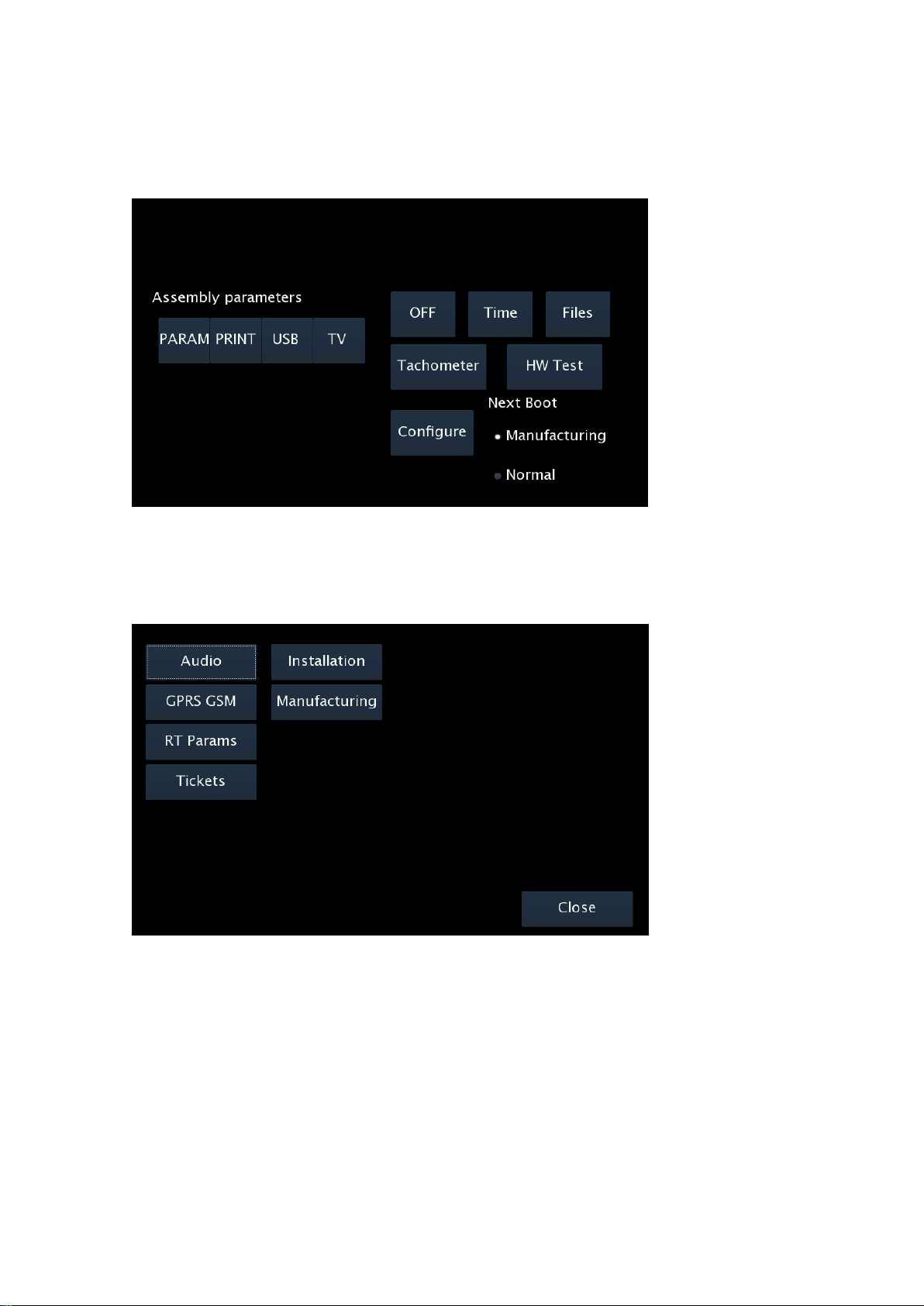
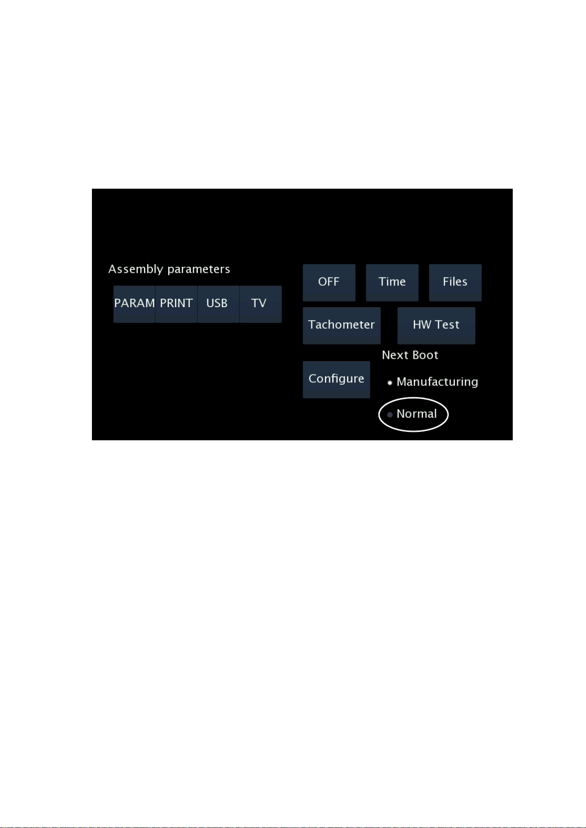
The start installer screen offers the following options:
OFF
Time: It updates the time and date of the terminal. This does not affect the taximeter
time, it is only active in non-taximeter configurations.
Files: Used for software updates
Tachometer: Calibration of the tachometer. This is only used in non-taximeter
configurations. This is not affecting the taximeter tachometer, which is calibrated inside
the taximeter screens.
INTERFACOM, S.A
9
3.1. CONFIGURATION PARAMETERS
When in the main Manufacturing screen, press “Configure”
The application configuration parameters will open.
These parameters are not metrologic, so they are not subject to legal sealing. This can
also be accessed with an installer magnetic card.

INTERFACOM, S.A
10
Audio
DspEchoCancel
Activates echo cancellation
Normally use this activated
Micr
Choose the used microphone
TC60 External mic connected to TC60
TV60 Internal TV60 mic
Merc Specific Mercedes microphone
Alt
Choose the used loudspeaker
TC60 External loudspeaker
TV60 Internal TV60 loudspeaker
Merc Specific Mercedes loudspeaker
Sounds Volume
Default system sounds volume
Reception of dispatch, messages, etc
Gsm Volume
Default phone calls volume
When you have finished press “Save” to store the new parameters

INTERFACOM, S.A
11
In case of vehicles with excessive echo, which can not be solved with the previously
explained parameters, it is also possible to adjust the microphone gain to reduce the echo.
Echo is not solved by increasing the volume: On the opposite, it is solved by lowering the
output volume or lowering the microphone gain.
The parameters affecting the microphone gain are:
Tel.Mic.Analog
Gain
Tel.Mic.Digital
Gain
Dsp Mic Out
Gain
Phone micro analog gain
Phone micro digital gain
Microphone gain at the
output of the DSP
These parameters are by default adjusted
so that they are valid for a majority of
vehicles. In case it might be necessary t o
adjust them:
- Select the parameter
- Lower with button “<”
- Increase with button “>”
In case the microphone gain is not
adequate, adjust with parameter
“Tel.Mic.Analog Gain” and check the
result. Normally it will be enough with this
only parameter.
These additional microphone gain parameters are not available on TC60 board
version 2, produced between 2007 and 2008
INTERFACOM, S.A
12
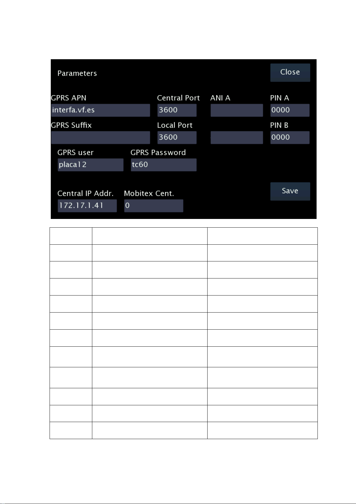
GPRS GSM
GPRS APN
Identification of the GPRS network
Central Port
UDP Port of the central programm
GPRS Sufix
GPRS Sufix, used as a second part of the
GPRS user.
Your network support will give you this
data if needed
Local Port
UDP Port of the local TC60 application
GPRS User
Identification of the TC60 in the GPRS
network
GPRS
Password
Password of the TC60 in the GPRS
network
Central IP
Address
IP Address of the Radiotaxi central
PIN GSMA
Enter the GSM A PIN
If the SIM is not in:
1.- First enter the PIN
2.- Then the SIM can be entered
PIN GSMB
Enter the GSM B PIN
If the SIM is not in:
1.- First enter the PIN
2.- Then the SIM can be entered
ANI GSMA
Enter the GSM A phone number
Needed for 112 applications
ANI GSMB
Enter the GSM B phone number
Needed for 112 applications
Mobitex Cent
Holland specific

INTERFACOM, S.A
13
RT Params
Name
Name of license owner
Licence
License number
Plate Number
Plate number
NIF
Fiscal ID
Car ID
ID of the car in the Radiotaxi
Driver 1..4
Driver codes of the 4 drivers
Company
Company code
Used by the Prima application
Term SN
TC60 serial number
Used by the Prima application
2 Drivers/Shift
Number of drivers per shift
Used by the Working Time Control application
Pins ShiftNr
To change the Shift number

INTERFACOM, S.A
14
Tickets
These screens are used to set all the data related to tickets. The data are:
Ticket Headers
6 ticket headers
Ticket Footers
8 ticket footers
Extras text
Extras text in the tickets
4 Manual Extras
1 Automatic Extra
Sweden specific
Inspection texts
Control Rapport
Plomb
Used only in Sweden
Sweden specific
TXT 1..4
Used only in Sweden

INTERFACOM, S.A
15
Installation
Operator
Installer who installs the device
Factory
Code of the workshop
Date
Installation date
Format YYYYMMDD
Bat. Calibration
Battery calibration
Touch Calibr.
Touchscreen calibration
EMV Type
Type of EMV payment
EMV SerialPort
Serial port where PinPad is
connected
Port 2 or Port 3 (see drawing ITC600003)
Taximeter type
Type of taximeter
Touchscreen calibration
If it is necessary to calibrate the display touchscreen, select “Touch Calibr”.
A pointer will appear near the left top corner. Press on the pointer, as precisely as possible.
Then the pointer will move to near the bottom right corner. Press on the pointer.
The touchscreen is now calibrated.
INTERFACOM, S.A
16
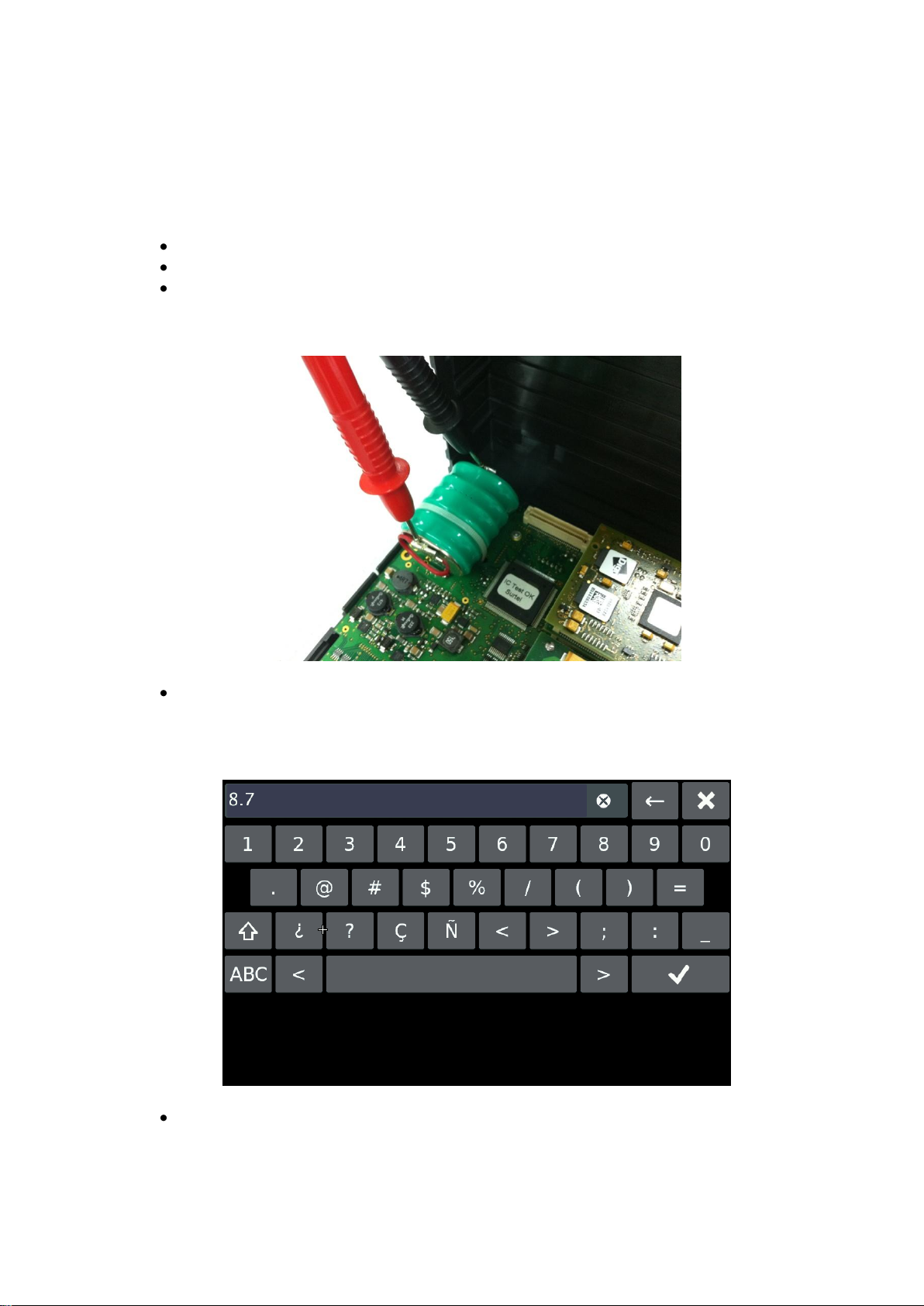
Battery calibration
This operation is only necessary in case that you have formated the board. Is not
neccesary if you change the battery.
To calibrate the battery:
Open the TC60 box so you can access the battery
Enter Bat. Calibration
Measure the Battery voltage with a tester. The value should be above 8V for a valid
calibration
The TC60 battery is charged up to a maximum between 7,8 and 8,5 V with an
ambient temperature of 25ºC. To calibrate it, wait at least until the value read on the
tester is 7,5 V, otherwise the calibration is wrong and battery may have a
breakdown.
Enter the value in format V.v and Enter
The battery is now calibrated. The voltage will be corrected the next time you reboot the
system.
INTERFACOM, S.A
17
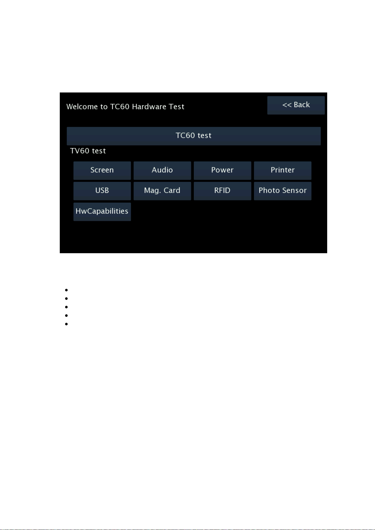
Hardware test
Press HW Test. These screens allow to test the TC60 and TV60. See the summary table
on Annex II to have all the verification options
It is necessary to test the correct connexion of all the elements and peripherals connected
to the TC60. In a typical installation, the verification must include:
Emergency button test
Contact key test
External lights
GSM antenna, coverage of the GSM phones
GPS antenna, GPS coverage
The TC60 installation cannot be considered as finished if the coverages of any of the
phones are not good enough. In that case, recheck the affected antenna. Take into
account that some vehicles have shielded windscreens, which attenuate the coverage.
INTERFACOM, S.A
18
3.2. SWITCH TO NORMAL MODE
Before installation is complete, change the working mode to Normal before the next restart
of the unit.
Select “Normal” in the “Next Boot” frame. Then you can turn the TC60 off. At next startup,
the TC60 will start in Normal mode.

INTERFACOM, S.A
19
4. TAXIMETER CONFIGURATION
With the TC60 in Normal mode, and with the taximeter in Free, open the sealed tariff cover
and connect a USB memory containing a valid tariff and installer key.
The screen will display the tariffs present in the USB. Select the adequate one.
If you have few tariffs in the USB, this will be faster than if you have a large number of
tariffs, so keep the number of tariffs as low as possible.
The taximeter configuration screen is displayed. In this screen the following operations can
be done:
1. Configure the “K” constant
2. Configure passwords
3. Set the clock
4. Reset totalizers
5. Record the tariff to the taximeter
4.1. CONFIGURING CONSTANT K
Press on the button “K”. The K constant configuration screen is entered.
It is possible to enter the K value directly, or to calculate it by doing a distance.
From this screen it is also possible to access:
External light type configuration
0 = Serial channel rooflight
1 = Parallel light
INTERFACOM, S.A
20
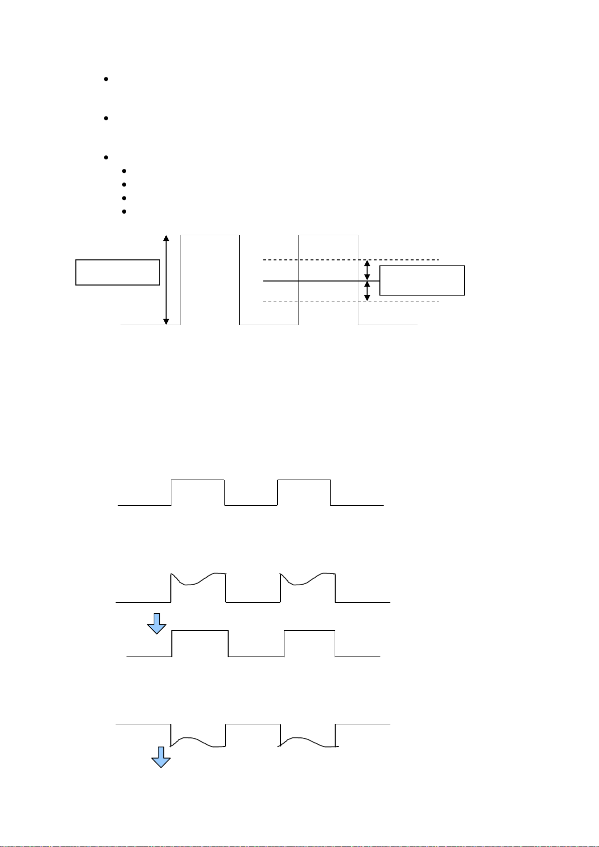
Adjustment of the trigger value for adequation to the car signal. The trigger value
counts from the center value of the signal
Modify Trigger value. The default 1000 mV is compatible with most cars. Change
only if the signal shape is not standard, and test until an adequate value is found.
The value must be in milivolts, without decimals. The default value is 1000
Lower than the vehicle signal amplitude / 2
Higher than a possible noise, so that it does not trigger by noise
Recommended value is the signal amplitude in milivolts / 4.
Valid values are between 400 and 2000.
4.1.1. PULL-UP CONFIGURATION
In some vehicles, the vehicle signal does not provide a high level signal, but an open circuit
instead. In these cases it is necessary to activate the pullup. Modify the value of the field
PULLUP by pressing on it.
Pull-up=0
Use if the vehicle signal has a good level for 0 and for 1
Pull-up=1
Use if the signal has a stable 0 level, but the 1 level given by the vehicle is an open circuit.
Pullup=2
Pull down. Use if the 1 value is stable, but the 0 value is an open circuit.
Signal amplitude
5000 mV
Proposed Trigger
1000 mV
This manual suits for next models
1
Table of contents
Other Interfacom Automobile Accessories manuals

Popular Automobile Accessories manuals by other brands

Blaupunkt
Blaupunkt BC OE2 Operating and installation instructions

Tow Tuff
Tow Tuff TTF-2762ACBR owner's manual

VBG
VBG Onspot Mounting instruction/Spare Parts List

SuperATV
SuperATV RBG-P-RZRXPTS installation instructions

Enelion
Enelion Wallbox installation guide

Ridetech
Ridetech MuscleBar 11289100 quick guide


