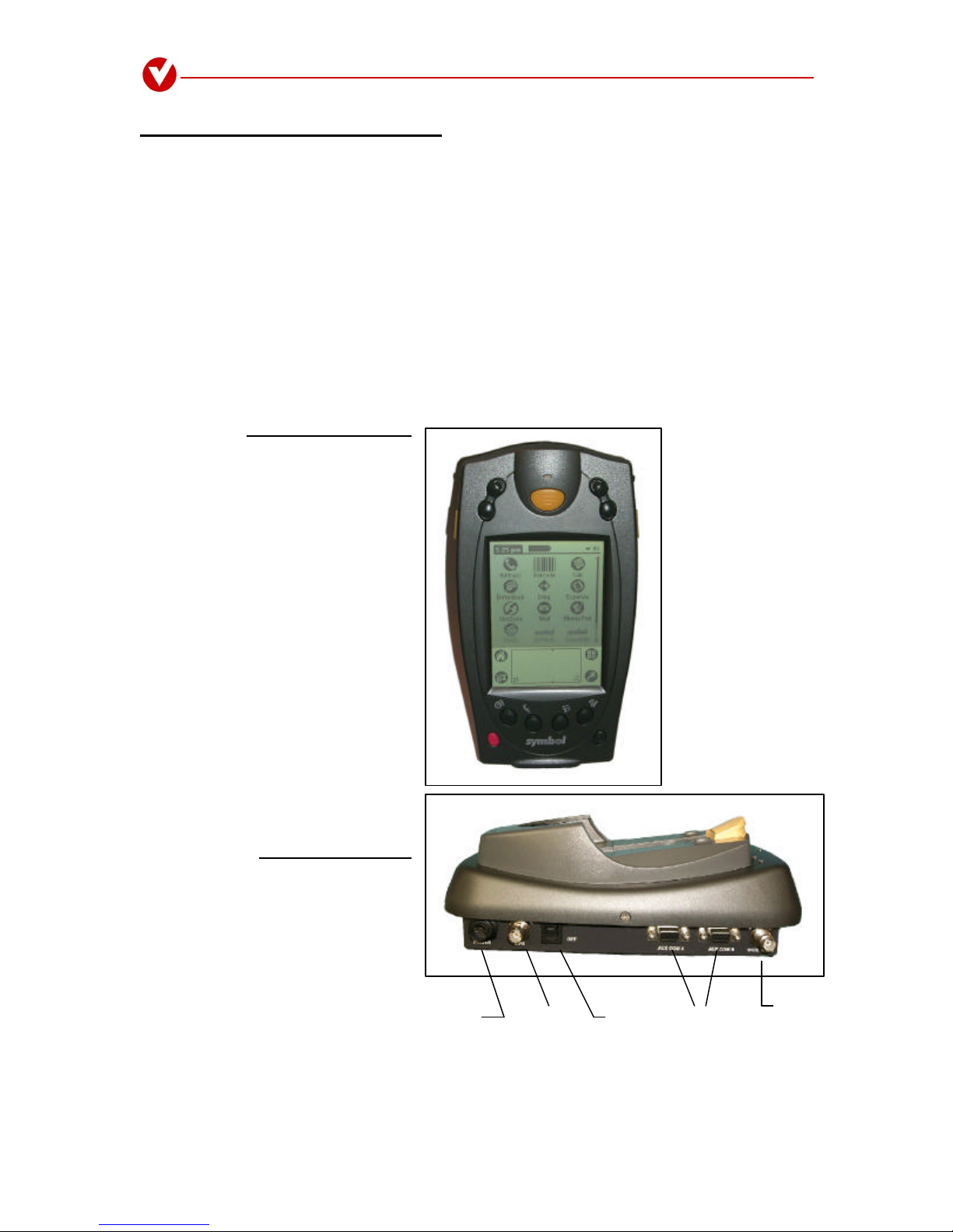
User Instructions VC1727C/R8
-4-
Suggested tools: Ideal Industries crimp tool, part #30-506, with a RG-174 die, part #30-576 and RG-58 die
part #30-502. These can be acquired through: Com-Kyle, Inc., 1-800-538-1578, www.shopeis.com.
4. Diagonal wire cutters.
Step 2: Refer to Assembly Instructions-C36 and C26a document accompanying these instructions for cable
stripping and crimping specifications.
3. Connecting power:
Installation Notes (4):
!**CAUTION -Special attention must be taken when connecting the device to power. Improper
power installation may cause damage to the VC1727C, damage to the vehicle, serious injury or even
death.
Make sure all exposed wire is properly insolated before applying power to the circuit.
Attaching the ground wire directly to the negative terminal of the battery is NOT recommended.
Besure all electrical connections are solid. Poor connections can cause electrical shorts and equipment
failure.
-------------------
Step 1: Connecting the ground wire -Attach the black ground wire from the power cord to any isolated
ground. If an isolated ground is not available, a filter may be purchased from your local automotive supply
store.
Step 2: Connecting the shield wire -This is the wire that is braided or foil wrapped around the red (positive
power) and black (Ground) wires. The purpose of this wire is to help prevent over currents from damaging
the cradle. Connect the power cord shield wire to any safe chassis ground.
Step 3: Connecting the positive power wire –Attach the positive (red) wire of the power cord to a fused 12
volt power source. A 5 amp 12–15 volt in-line fuse is recommended.
If a fused power source is not available a fuse holder with a 5 amp fuse has been supplied with the cradle.
Attach one end of the fuse holder to the to the positive 12 volt supply and the other end to the cradle power
cord.
Do not install the fuse at this time.
4. Electrical check:
Step 1: Using the Digital Multi-meter test the electrical continuity of the power connections.
a) On the VC1727C power cord the voltage IN power socket is positioned to the left of the plug guide
slot of the socket housing. It has a small raised dot next to it. Attach a multi-meter test lead to the
power cord side of the fuse holder and the other test lead to the voltage IN socket. The meter should
indicate continuity of the circuit.
b) Check for shorts to ground by connecting one lead of the multi-meter to a ground plane and the other
to voltage IN on the power socket. There should be no continuity.
c) If the battery is disconnected, check continuity between the battery side of the fuse holder and the
positive battery cable that connects to the battery terminal. (The battery cable MUST be disconnected
from the battery to conduct this test). The meter should indicate continuity.