2 Installation Guide
Introduction
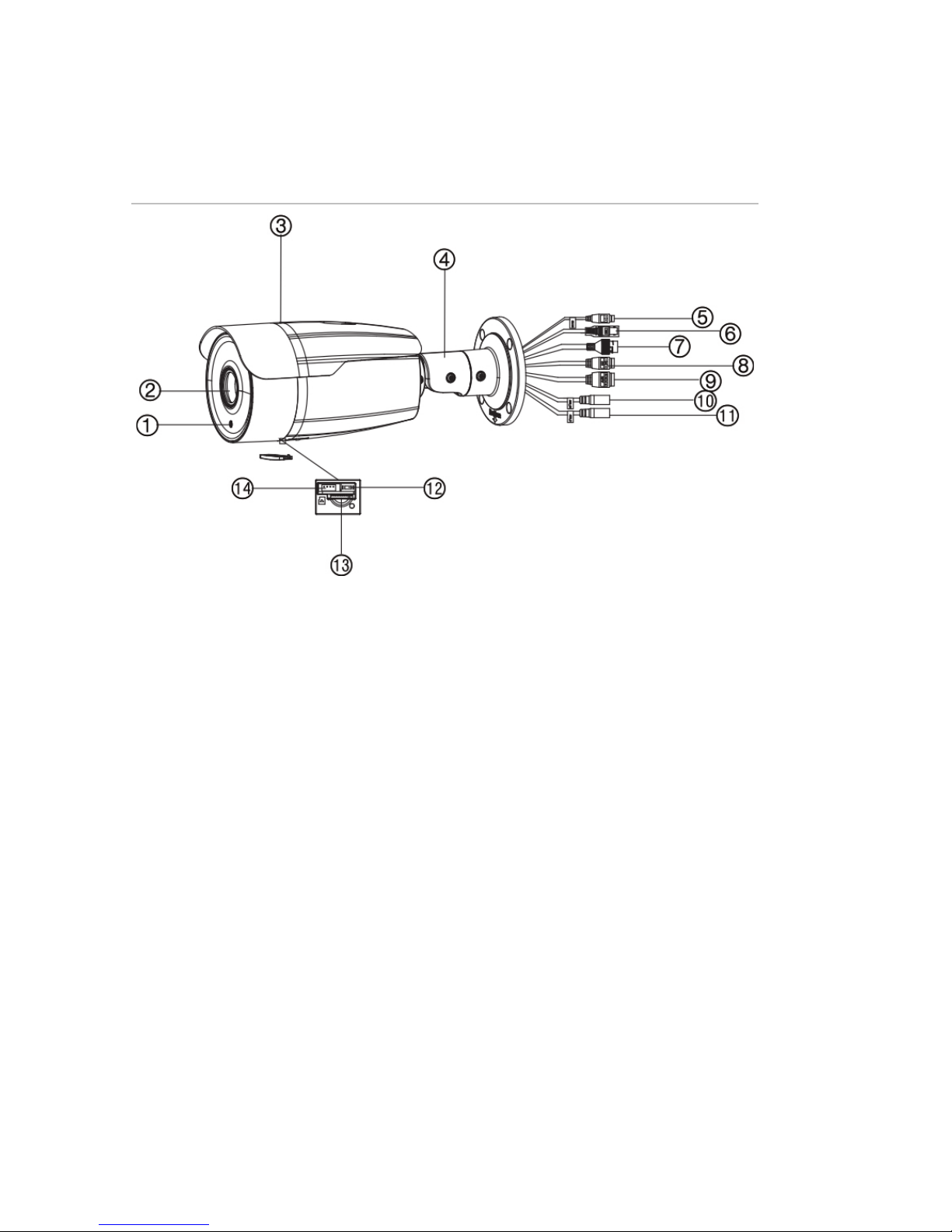
Product overview
This is the installation guide for TruVision IP thermal camera
models:
TVB-5701 (IP Thermal Bullet Camera, 384x288, 15 mm)
TVB-5702 (IP Thermal Bullet Camera, 384x288, 35 mm)
TVB-5706 (IP Thermal Bullet Camera, 640x512, 15 mm)
TVB-5707 (IP Thermal Bullet Camera, 640x512, 25 mm)
Installation
This section provides information on how to install the
cameras.
Installation environment
When installing your product, consider these factors:
•Electrical: Install electrical wiring carefully. It should be
done by qualified service personnel. Always use a proper
PoE switch or a 12 VDC UL listed Class 2 or CE certified
power supply to power the camera. Do not overload the
power cord or adapter.
•Ventilation: Ensure that the location planned for the
installation of the camera is well ventilated.
•Temperature: Do not operate the camera beyond the
specified temperature, humidity or power source ratings.
The operating temperature of the camera without heater