Interlogix IS-ZW-TSTAT-500 Operation manual

© 01/01/19 UTC Fire & Security. All rights reserved. 1 / 14 P/N 466-5519 • REV 0.01 • 24MAY19
24VAC or Battery Powered Z-Wave Thermostat
Installation/User Guide
Content
Description........................................................................................1
Battery Powered Operation...............................................................1
Installation Steps...............................................................................2
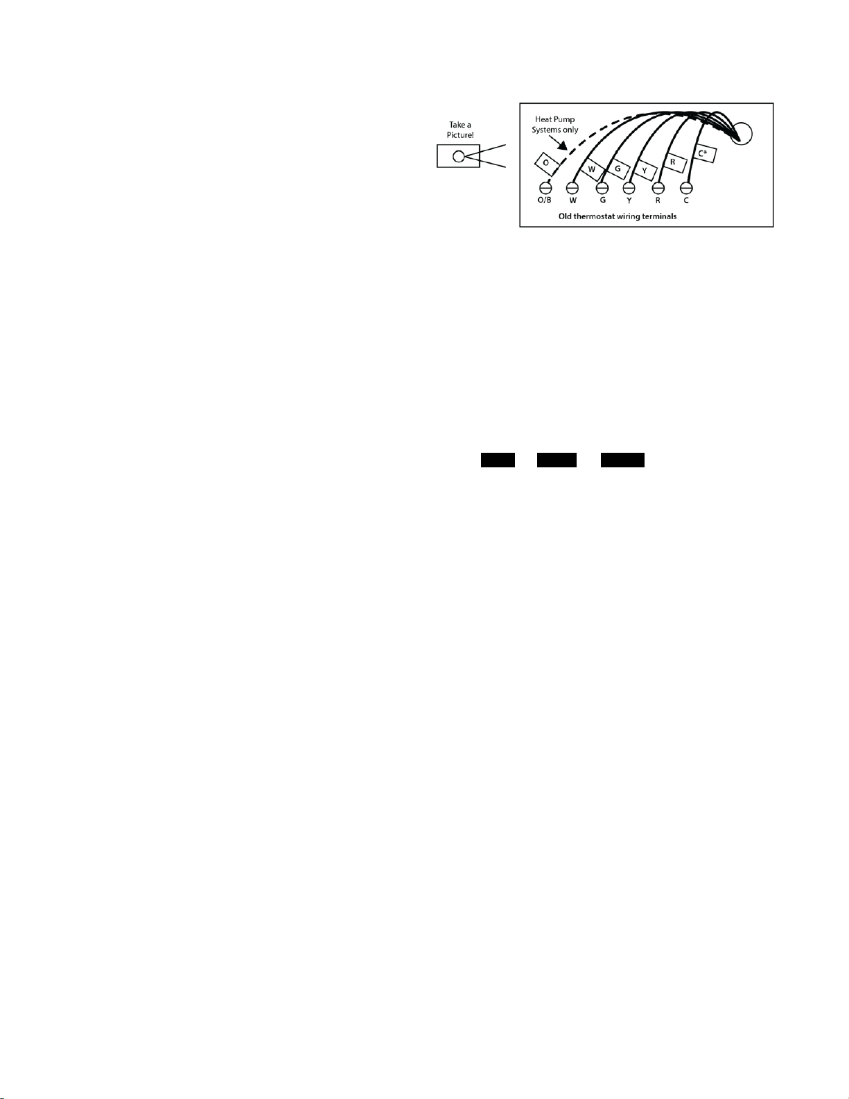
Remove old thermostat.....................................................................2
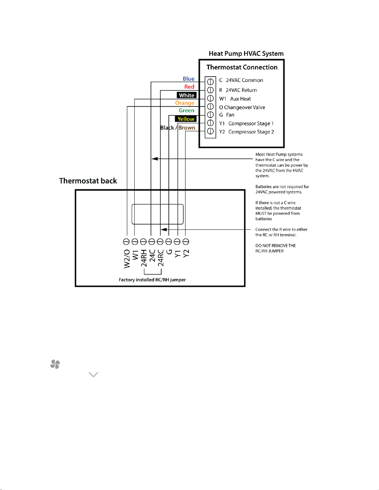
Heat Pump HVAC Systems Wiring...................................................3
Mount the thermostat........................................................................3
Standard Gas/Electric HVAC System Wiring....................................5
Heat Pump HVAC System Wiring.....................................................6
Thermostat Setup: Configure for HVAC System...............................7
Changing the HVAC System Setup ..................................................7
Menu Options....................................................................................7
Advanced System Settings Menu.....................................................8
Advanced Settings............................................................................8
Operation ........................................................................................10
Backlight and Button Operation ......................................................10
Thermostat Backlight Display..........................................................10
Setpoint Change .............................................................................11
Fan Modes......................................................................................11
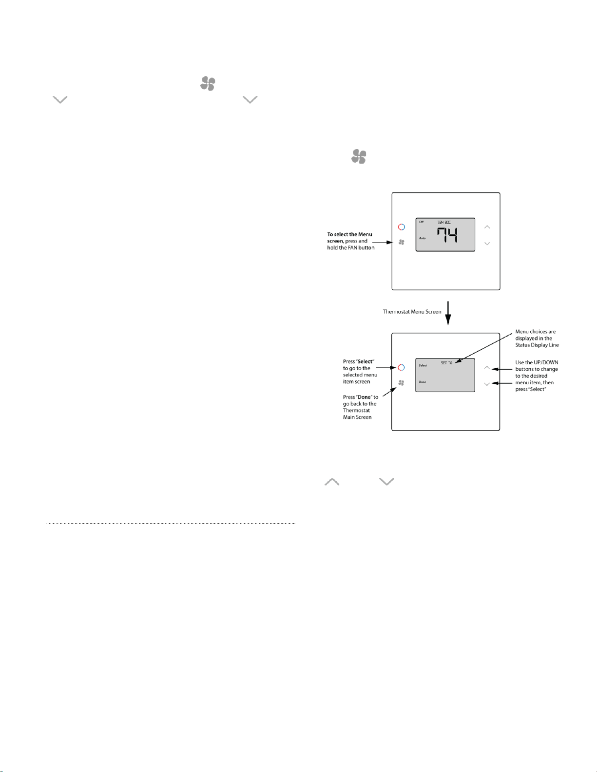
Thermostat Menu Mode..................................................................12
Menu Mode Options........................................................................12
Thermostat Operation.....................................................................13
Minimum Run Time (MRT)..............................................................13
Minimum off Time (MOT)................................................................13
Z-Wave
®
Operation.........................................................................13
FCC Compliance.............................................................................14
Contact Information
For contact information, see www.utcfireandsecurity.com or
www.interlogix.com.
For technical support, toll-free: 888.437.3287 / 855.286.8889
in the US including Alaska, Hawaii, Puerto Rico, and
Canada.
Outside toll-free area, contact your dealer.
© 2019 UTC Fire & Security Americas Corporation, Inc.
Interlogix is part of UTC Climate Controls & Security, a unit
of United Technologies Corporation.
All rights reserved.
Safety Information
WARNING: CHOKING HAZARD. The product accessory bag
contains items that could be choking hazards. Please
keep away from small children.
AVERTISSEMENT: Le sachet de produits accessoires contient des
éléments qui pourrait présenter un danger
d’étouffement. Veuillez garder hors de la
portée des jeunes enfants.
Description
This thermostat is compatible with most HVAC systems,
including the following:
x24VAC systems
Note: Requires both the 24VAC R and C (“common”) wires unless
battery powered.
xStandard gas/oil/electric heating systems
1 stage heating and cooling
2 stage heating and cooling
xHeat Pump systems:
1 stage heating and cooling
2 stage heating and cooling
2
nd
or 3
rd
stage Auxiliary heating (heat strips)
Warning! Do NOT use for line voltage controls
(120/240VAC)
The thermostat can either be powered by batteries or
24VAC.
Battery Powered Operation
The thermostat can be powered by four AA Alkaline
batteries. The thermostat will operate for approximately two
years on four AA Alkaline batteries depending on the
frequency of user operations and backlight operation.
Always use alkaline batteries and replace all four at the
same time with NEW batteries.

2 / 14 P/N 466-5519 • REV 0.01 • 24MAY19
Z-Wave Operation when Battery Powered
IMPORTANT: If the thermostat is installed on a Z-Wave
network, while it is battery powered, it
does not work as a Z-Wave repeater.
24VAC Powered Operation
Powering the thermostat with 24VAC power requires both
the C wire (24VAC common wire - typically blue) and the R
wire (24VAC hot wire - typically Red). If the C wire is not
available, then batteries are required.
Note: If the thermostat is powered from 24VAC, do not install
batteries!
Z-Wave Operation when 24VAC powered
If the thermostat is installed on a Z-Wave network while it is
24VAC powered, it operates as an always-on Z-Wave
repeater.
Installation Steps
1. Remove old thermostat
2. Install TBZ500 IS-ZW-TSTAT-500 (W for whit, B for
black)
3. Set up the thermostat for the HVAC system
4. Enroll on Z-Wave network
Remove old thermostat
1. Turn off power to the HVAC system. Usually at the
HVAC system or the circuit breaker panel.
2. Remove cover of old thermostat to expose the wiring
terminals.
xTake a picture of the wiring terminals! This will help
with troubleshooting later if needed.
xMark the wires attached to the terminals with the
wiring labels included.
3. Use the terminal labels and not the wiring color to mark
the wires.
4. Remove the old thermostat base.
CAUTION: Don’t let the wires slip into the wall.
Figure 1: Thermostat Wiring
Note*: The C wire (24V common) may not be present.
If C wire is not present, the thermostat must be powered by
batteries.
ATTENTION: If the C wire is present, you can power,
DO NOT INSTALL BATTERIES!
Note: Mark the wires according to the terminal markings. There
may be additional wires such as Y2, W2. If you have RC
and/or RH connections, see below. Other wires are not
used:
xWiring colors: While the wiring terminals markings are
intended to match the wire color (R=Red,G=Green,
W=White,Y=Yellow,O=Orange), not all installations
were correctly installed this way. Be sure to follow the
terminal marking when marking the wires, even if the
wire color doesn’t match.
x24VAC Power: The thermostat requires the 24VAC C
(common) wire be connected to operate without
batteries. Otherwise 4 x AA batteries are required.
Note that the 24VAC C common wire (usually Blue) may
be present but not connect to 24VAC common at the
HVAC system end. Be sure to check for 24V across R
and C terminals if the thermostat does not power up
without batteries. If there is no C “common” wire,
batteries are required.

P/N 466-5519 REV 0.01 • 24MAY19 3 / 14
Connecting Wires (most common connections)
Mount the thermostat base to the wall using the wall anchors
and screws provided; level as needed. Connect the wires
according to the HVAC system type as below.
Standard Gas/Electric HVAC System Wiring
Figure 2: Single stage heating and cooling
Note: Connect the wires as marked from the HVAC system to the
corresponding terminals on the thermostat back.
*C wire (24VAC common) may not be present. If not,
batteries must be installed.
R vs RC and RH Connections
xSingle Transformer HVAC Systems: Typical modern
central HVAC installations have an integrated heating
and cooling system with a single 24VAC transformer.
For these systems, there is only one 24VAC “R” wire
and it can connect to either the RC or RH terminal on
the thermostat. The thermostat is supplied with an RC-
RH jumper installed. Do not remove the jumper for
common transformer HVAC systems.
xSeparate Transformer HVAC Systems: Some
installations may have separate heating and cooling
systems with separate 24VAC transformers. For those
systems there will be a separate “R” wire for the heating
system (RH) and cooling system transformers (RC).
To connect separate transformer systems, FIRST REMOVE
THE SUPPLIED RH-RC JUMPER. Then connect the
heating “R” wire to the RH terminal and the cooling “R” wire
to the RC terminal on the thermostat.
Heat Pump HVAC Systems Wiring
Figure 3: Single stage heating and cooling
Notes: Connect the wires as marked from the HVAC system to the
corresponding terminals on the thermostat back.
*C wire (24VAC common)
Heat Pump systems usually have the C wire connected to
the thermostat. If there isn’t a C wire, batteries must be
installed.
** O (Orange) or B (Brown) wire (changeover valve)
connect to the W2/O terminal on the thermostat.
Be sure to set the correct changeover operation (O =
changeover with Cool, B = changeover with Heat) in the
SETUP menu.
Connect the R wire to either RC or RH terminal.
Finish Wiring
xIf you have additional wires for 2 stage systems (W2,
Y2), see the wiring diagrams on page 5 and 6.
xCheck that the wires are screwed into the terminal
blocks firmly.
xGently pull on the wires to confirm the connection.
xPush all the excess wiring back into the wall.

4 / 14 P/N 466-5519 • REV 0.01 • 24MAY19
Mount the thermostat
x24VAC Powered Thermostat: If the thermostat is
24VAC powered (24VAC common “C” wire is
connected), DO NOT INSTALL BATTERIES!
Figure 4: 24VAC Powered Thermostat
1. Install the thermostat on to the base.
2. Turn on power to the HVAC system/thermostat.
xBattery Powered Thermostat: If the thermostat is
battery powered (NO 24VAC common “C” wire
connected), install 4 NEW Alkaline AA batteries into the
back of the thermostat.
Figure 5: Battery Powered Thermostat
1. Install the thermostat on to the base.
2. Turn on power to the HVAC system/thermostat.

P/N 466-5519 REV 0.01 • 24MAY19 5 / 14
Standard Gas/Electric HVAC System Wiring
Figure 6: Thermostat wiring connection with standard HVAC system
Note: Remove the factory installed RC/RH jumper.
Thermostat Setup: Standard Gas/Electric HVAC
Systems
For Single Stage Heat/Cool Systems:
Go to the Menu screen by pressing and holding the FAN
button for 5 seconds.
Press the down arrow to select the SYSTEM menu and
press Select.
CAUTION: Typical thermostat wiring colors, verify that
original wiring matches. Colors may be different.
Set the following:
System Type
xSet to STANDARD
Fan Type
xSet to GAS for typical gas furnace (fan is controlled by
the furnace)
xSet to ELECTRIC for electric heat (fan on with heat
call).
For Two Stage Heat/Cool Systems:
Go to ADVANCED SYSTEMS SETTINGS menu.
From the Setup menu screen, press and hold the Fan
button and Down arrow buttons for 5 seconds. Use
the Down arrow button to select the following:
x2nd Stage Heat Enable: Enable second stage heating
output.
If a single stage heating system, leave this set to N.
If a 2 stage heating system, set to Y to enable.
x2nd Stage Cool Enable: Enable second stage cooling
output.
If a single stage cooling system, leave this set to N.
If a two stage cooling system, set to Y to enable.
Default Thermostat Setup:
xType: Standard HVAC
xFan Type: Gas Heat
1 Stage heating
1 Stage cooling
Note: No Setup change required for this configuration.

6 / 14 P/N 466-5519 • REV 0.01 • 24MAY19
Heat Pump HVAC System Wiring
Figure 7: Thermostat Wiring connection with heat pump HVAC system
CAUTION: Typical thermostat wiring colors, verify that original wiring matches. Colors may be different.
Note: If you get heating when you expected cooling or vice versa, change the Change Over type to the opposite setting.
Thermostat Setup: Heat Pump HVAC Systems
For Single Stage Heat/Cool Systems:
1. Go to the Menu screen by pressing and holding the FAN
button for 5 seconds.
2. Press the down arrow to select the SYSTEM menu
and press Select.
Set the following:
xSystem Type: Set to HEAT PUMP
xChange Over: For changeover with cooling systems
(Orange wire): set to WITH COOL (most common and
default setting).
For changeover with heating systems (Brown wire): set
to WITH HEAT.
You must configure the thermostat’s changeover valve
setting to work correctly with your HVAC system.
Check your system information to be sure and note the color
of original thermostat wire and the terminal it was connected
to.
No matter what the old stat connection was (O or B),
connect the wire to the thermostats W2/O terminal.

P/N 466-5519 REV 0.01 • 24MAY19 7 / 14
For Two Stage Heat/Cool Systems:
Go to Advanced Systems Settings menu. From the Setup
menu screen, press and hold the Fan and Down arrow
buttons for 5 seconds. Use the Down arrow button
to select the following:
xAUXHEAT: If you have auxiliary heat strips, set this to Y
to enable. (Default is Y).
x2nd Stage Heat Enable: Enable second stage heating
outputs.
If a single stage heating system, leave this set to N
If a 2 stage heating system, set to Y to enable.
x2nd Stage Cool Enable: Enable second stage cooling
outputs.
If a single stage cooling system, leave this set to N.
If a two stage cooling system, set to Y to enable.
Thermostat Setup: Configure for HVAC
System
The thermostat must be set up for the correct HVAC system
type and configuration for proper operation.
Preset HVAC System settings
The thermostat is preset for the following typical HVAC
system configuration:
xHVAC system type: Standard gas/electric
xHVAC fan type: Gas heat
xHVAC heating stages: one
xHVAC cooling stages: one
If the thermostat is installed on this type HVAC system,
the System setup does not need to be changed.
Installation is complete.
For thermostats installed on a Heat Pump HVAC system or
any HVAC configuration other than the preset settings, the
System settings need to be changed in the SYSTEM setup
menu to match the HVAC system.
Changing the HVAC System Setup
To change the thermostats HVAC system settings, first
select the Menu Screen and then select the SYSTEM menu.
Follow instructions below to access the SYSTEM menu.
Note: To conserve battery life, the thermostat backlight turns off
after a short time of no activity. The first press of any button
will turn on the backlight but will not initiate any action other
than turning on the backlight. Press the button again to
initiate the action desired. If the backlight is already on,
button presses work with the first press.
Go to Menu Screen
From the Thermostat Main Screen, press and hold the FAN
button until the Menu screen is displayed.
Figure 8: Main Screen
Menu Options
When the thermostat Menu Screen is displayed, use the Up
or Down arrow buttons to scroll through the
following options:
xSETUP (user preference settings)
xSYSTEM (HVAC system setup)
xZWAVE (install/uninstall from Z-Wave network)
xHUMIDITY
xINFO (firmware versions and Z-Wave network
information)

8 / 14 P/N 466-5519 • REV 0.01 • 24MAY19
Select System setup
To change the HVAC system default settings, scroll down to
the SYSTEM menu item and press “Select”.
System Setup Menu
The SYSTEM menu is used to set up the thermostat for the
correct HVAC system type.
System Type
xFor Standard Gas/Electric systems, select “Standard”.
This is the default setting.
xFor Heat Pump systems, use the Up/Down arrows to
change to “Heat Pump”
xPress Select to set.
xPress Done to exit
Fan Type (For Standard HVAC systems only)
xFan type depends on the heating system type.
xFor Gas heat: select “GAS”. This is the default setting.
xFor Electric heat: use the Up/Down arrows to change to
“ELECTRIC”.
xPress Select to set
xPress Done to exit
Changeover Type (for heat pump HVAC systems
only)
The changeover (or reversing) valve is used to change from
heating to cooling operation. It is either a changeover with
cooling type (Orange wire) or changeover with heating type
(Brown wire). Most are changeover with cooling, which is
the default setting.
xFor Changeover with Cooling systems (Orange wire),
select “WITH COOL”. This is the default setting.
xFor Changeover with Heating systems (Brown wire),
use the Up/Down arrows to change to “WITH HEAT”.
xPress Select to set
xPress Done to exit
Not sure which Changeover type?
Check the existing thermostat connections to help determine
this.
xIf the original system had an orange wire connected to
the “O” terminal, then this is a “changeover with cool”
system.
xIf there was a Brown wire connected to the “B” terminal,
then this is a “change over with heat” system.
xSet the Change Over setting accordingly.
CAUTION: These are typical wiring colors/connections
and may differ.
xIf heating comes on when cooling is expected or
vice versa, change the “Change Over Type” to the
opposite setting.
Advanced System Settings Menu
The Advanced System Settings Menu provides for addition
system setup options. These settings can affect system
operation and should only be changed by qualified HVAC
installers.
To access the Advanced System Settings menu, first press
and hold the Fan button to get to the MENU screen.
Continue to hold down the Fan button and press and
hold the Down arrow button for 5 seconds. The first
menu item in the Advance System Settings menu “Display
Lock” will be displayed. Use the Up/Down arrow buttons to
scroll through the menu options to the desired setting. Press
“Select” (Mode) button to change a setting. Once it
begins to flash, use the Up/Down buttons to select the
desired setting. Press the “Select” button to accept the
new setting (flashing will stop).
Advanced Settings
Table 1: Advance Settings
Display Lock Range: Y or N Default: N
xY = Display LOCKED
xN = Display UNLOCKED
Allows the thermostat buttons to be locked. When the
buttons are locked, none of the thermostat buttons will
function as normal.
To unlock the thermostat, press and hold the FAN button
for 5 seconds to access the Setup screen (it’s the
only button that works in the lock mode). Access the
Advanced Settings Menu (as above) to turn the Display
Lock off.
Test Mode Range Y or N Default: N
Test mode shortens the system built-in delays (like MOT
and MRT)
xY= Test mode on. Reduces all delays to 10 sec for
quicker system testing
xN= Test mode off. Normal system delays
Test mode will time out after 30 min and return to normal
operation.

P/N 466-5519 REV 0.01 • 24MAY19 9 / 14
Table 1: Advance Settings continued
Aux Heat
Enable* Range: Y or N Default: Y
Enables the Auxiliary Heat operation.
Typically, the Aux Heat will be heat-strips in a Heat Pump
system
Aux heat control is wired to the W1 terminal.
Note*: Heat pump systems only.
2nd Stage Heat
Enable Range: Y or N Default: N
Enables the 2nd Stage Heat operation
2nd Stage Cool
Enable Range: Y or N Default: N
Enables the 2nd Stage Cool operation
Minimum Run
Time Range: 1- 9
Minutes Default: 3
Sets the Minimum Run Time (MRT) delay before a
heating/cooling cycle can turn off.
Sets heating/cooling cycle time. Prevents rapid on/off
cycling.
Minimum Off
Time Range: 5-9
Minutes Default: 5
Sets the Minimum Off Time (MOT) delay before another
heating/cooling cycle can begin. Provides compressor
short cycle protection. “WAIT” is displayed on screen
when active.
Heat Setpoint
Max Range: 30°F to
109°F (0°C-
43°C)
Default: 90°F
(32°C)
Sets the maximum heating setpoint value. Will not ramp
or accept setpoints higher than this maximum.
Cool Setpoint
Min Range: 33°F to
112°F (2°C-
45°C)
Default: 60°F
(15°C)
Sets the minimum cooling setpoint value. Will not ramp or
accept setpoints lower than this minimum.
Heat Blower Off
Delay Range: 0-90
seconds Default: 0 (off)
Sets the system blower delay off time after a heat call
ends (fan purge).
Cool Blower Off
Delay Range: 0-90
seconds Default: 0 (off)
Sets the system blower delay off time after a cool call
ends (fan purge).
Heat - Cool
Delta Range: 3° - 15° Default: 3°F
(1°C)
Sets the minimum separation between heating and
cooling setpoints.
Table 1: Advance Settings continued
Setpoint Push
xAttempts to lower the cooling setpoint below the
heating setpoint will PUSH the heating setpoint down
to maintain the heat/cool delta separation.
xAttempts to set the heating setpoint above the cooling
setpoint will PUSH the cooling setpoint up to maintain
the setpoint heat/cool delta separation.
Heating Stage 1
On Threshold Range: 1° to 6° Default: 1°
Sets the delta from setpoint that stage 1 heating starts.
Heating Stage 1
Off Threshold Range: 0° to 5° Default: 0°
Sets the delta from setpoint that stage 1 heating stops.
Stage 1 turns off at setpoint + Delta Stage 1.
Heating Stage 2
On Threshold Range: 2° to 7° Default: 2
Sets the delta from setpoint that stage 2 heating starts.
Heating Stage 2
Off Threshold Range: 0° to 6° Default: 0°
Sets the delta from setpoint that stage 2 heating stops.
Stage 2 turns off at setpoint + Delta Stage 2.
Aux Heat On
Threshold Range: 3° to 8° Default: 3°
Sets the delta from setpoint that stage 3 heating starts.
Aux Heat Off
Threshold Range: 0° to 7° Default: 0°
Sets the delta from setpoint that stage 3 heating stops.
Stage 3 turns off at setpoint + Delta Stage 3.
Cooling Stage 1
On Threshold Range: 1° to 7° Default: 1°
Sets the delta from setpoint that stage 1 cooling starts.
Cooling Stage 1
Off Threshold Range: 0° to 6° Default: 0°
Sets the delta from setpoint that stage 1 cooling stops.
Stage 1 turns off at setpoint - Delta Stage 1
Cooling Stage 2
On Threshold Range: 2° to 8° Default: 2°
Sets the delta from setpoint that stage 2 cooling starts.
Cooling Stage 2
Off Threshold Range: 0° to 7° Default: 0°
Sets the delta from setpoint that stage 2 cooling stops.
Stage 2 turns off at setpoint - Delta Stage 2.
Restore
Defaults Range: Yes, No Default: No
Restores all settings to factory defaults.
Press Yes to restore defaults
Press No to exit and not restore defaults

10 / 14 P/N 466-5519 • REV 0.01 • 24MAY19
Operation
Backlight and Button Operation
The thermostat backlight is normally set to go out after 20
seconds of no button presses to conserve battery power. If
the backlight is off, the first button press of any button will
only turn on the backlight, see Figure 1 (items 5-8). Once the
backlight is on, the buttons function normally.
Figure 9: Main Thermostat Screen
Figure 1 Legend:
1) Backlit Display
2) Text Display Line
3) Room Temperature
4) Button Mode Status Icon
5) Mode Touch Buttons
Heating/cooling Mode Selections
6) Fan Mode Icon
7) Temperature Setting Touch Button (Warmer)
8) Temperature Setting Touch Button (Cooler)
Thermostat Backlight Display
Figure 10: Thermostat Backlight Display
(IS-ZW-TSTAT-500)
Table 2: System Operation Modes
Icon Description
System is ON and heating. If flashing,
minimum run time (MRT) is active
System is ON and cooling. If flashing,
minimum run time (MRT) is active
LLOW BATTY
Battery indicator
Display lock indicator
Z-Wave network indicator
Stage Indicators
x“1” = Stage 1 heating or cooling is ON
x“2” = Stage 2 heating or cooling is ON
x“3” = Stage 3 heating (Aux Heat) is ON
For heat pump systems only:
x“Heat-E” = Emergency heat mode active
Figure 11: Setting the System Mode
System Modes
xOff: System is off. No heating or cooling will come on.
If system was on, it will turn off immediately.
xHeat: Only heating will occur.
xCool: Only cooling will occur.
xAuto: Heating or cooling will come on according to the
heating and cooling setpoints. The system will
automatically switch between heating and cooling
modes as needed to maintain the setpoints.

P/N 466-5519 REV 0.01 • 24MAY19 11 / 14
Special Heat Pump Mode: Emergency Heat
xHeat-E: An additional system mode, “Heat-E” for
Emergency Heat will be displayed if the HVAC System
Type is set to Heat Pump. If there is a compressor
failure with the Heat Pump system, setting the mode to
Emergency Heat will allow the supplemental Aux Heat
to come on first whenever there is a call for heating. It
also disables the compressor output to prevent further
damage to the HVAC system.
CAUTION! Emergency Heat should only be used for emergencies
until the HVAC system can be repaired. Running the
system in Emergency Heat mode is commonly the
most expensive mode since only the electric heat
strips are being used instead of the more efficient
heat pump compressor.
Figure 12: Setting the Heating or Cooling Temperature
Setpoint
Setpoint Change
To change the setpoint, press the Up or Down arrow
buttons. The screen will switch to the setpoint change screen
(as above) and show the current setpoint of the current
heating or cooling mode. Adjust setpoint temperature up or
down with the arrow buttons.
Note: When in the Setpoint Change screen, pressing the MODE
button will switch the setpoint being displayed between the
Heat and Cool setpoints.
xSetpoint Push: The cooling setpoint cannot be set
below the heating setpoint. The thermostat will “push”
the heating setpoint lower if the cooling setpoint is set
below the current heating setpoint. A 3° separation is
maintained between the heating and cooling setpoints.
The same is true for raising the heating setpoint above
the cooling setpoint. The thermostat will “push” the
cooling setpoint up to maintain the 3° separation.
Figure 13: Setpoint Change Screen
Fan Modes
xAuto: Fan automatically operated by the HVAC system.
(normal setting)
xOn: Manual Fan mode. Fan stays on until mode is
changed back to Auto, independent of the heating or
cooling system operation.
Figure 14: Setting the Fan Mode

12 / 14 P/N 466-5519 • REV 0.01 • 24MAY19
Thermostat Menu Mode
The Thermostat has a menu of setup and information
displays.To change to the Menu Mode, press and hold the
FAN button for 5 seconds. The display will change to
the Menu Mode and display the Setup screen. Use the
Up/Down arrow buttons to scroll through other menu items.
Figure 15: Thermostat Main Screen
Menu Mode Options
xSETUP: User preference settings
xSYSTEM: Thermostat HVAC system settings
xZWAVE: Z-Wave network install or remove
xINFO: Displays thermostat version and setup info
Setup Menu
User preference settings are as followed:
xFahrenheit or Celsius: Select the temperature display
mode.
xBacklight Timeout: Sets the time from last button
press that the backlight will turn off; range: 10 - 30
seconds.
Note: Long backlight timeouts will reduce battery life.
If the thermostat is powered from 24VAC, the backlight
timeout can be set to “0” which will keep the backlight
on continuously.
xTemperature Sensor Calibration: Change the
temperature calibration by ±7°. Use the Up/Down arrow
buttons to change to the desired temperature displayed.
xHumidity Sensor Calibration: Change the humidity
calibration by ±7%. Use the Up/Down arrow buttons to
change to the desired humidity displayed.
xStatus Line display: Select Setpoints or Humidity to
be displayed on the upper status line.
System Menu
xSystem type: Select the system type, Standard or
Heat Pump
Fan type (standard systems only)
xSelect fan type:
Gas (typical default setting) or Electric
Change over type (heat pump systems only)
xSelect the Changeover type:
Changeover WITH COOL (typical default setting)
Changeover WITH HEAT
See Installation Guide for more information on System setup
and the Advanced Systems Menu.
Z-Wave Menu
This menu item allows the thermostat to be enrolled to the Z-
Wave network. Follow the instructions shown in the Z-Wave
Operation section (page 18) to enroll the Thermostat onto
the network.
INFO Menu
The INFO menu displays information about the thermostat.
Use the Up/Down buttons to scroll through the various items.
Thermostat information displayed:
xVersion: Thermostat firmware version
xZWAVE: Z-Wave firmware version
xNode ID: Z-Wave Node ID
xHome ID: Z-Wave Home ID
xSystem type: Displays current System Type settings
(Standard or Heat Pump)
If System Type = Standard
xFan type: Displays current Fan Type setting

P/N 466-5519 REV 0.01 • 24MAY19 13 / 14
If System type = Heat Pump
xChangeover type: Displays current Change Over valve
(reversing valve) setting
xAC or Battery Powered: AC POWER will be displayed
if power by 24VAC
Thermostat Operation
Minimum Run Time (MRT)
The thermostat has a Minimum Run Time (MRT) delay after
the start of any heating or cooling call. This minimum run
time assures even heating and cooling cycles. The MRT will
keep the system on, even if it reaches the setpoint room
temperature, or you change the setpoint to a temperature
that would satisfy the call, until the MRT expires. Changing
the Mode to OFF will cancel the MRT and the system will
turn off immediately. The MRT can be adjusted in the
Advanced Settings menu of the thermostat.
Note: When MRT is active, the heating or cooling icon will be
flashing.
Minimum off Time (MOT)
The thermostat has a Minimum off Time (MOT) delay after
any heating or cooling cycle ends. This delay prevents rapid
heating/cooling cycles and also provides “short cycle
protection” for the system compressor. This delay may be
noticeable when you change a setpoint and it does not
respond immediately due to the MOT delay timer preventing
the system from restarting. The MOT delay time can be
adjusted in the Advanced Settings menu of the thermostat
but there is a minimum of a 5 minute delay to assure
compressor protection.
Note: When MOT is active, the thermostat Status Display shows
“WAIT”.
Z-Wave
®
Operation
xThermostat Battery Operation: If the thermostat is
installed in a Z-Wave network while powered by
batteries, it will be enrolled as a Z-Wave FLiRs
(frequently listening receiver slave) type device. This is
a power saving mode that conserves the batteries by
keeping the radio asleep most of the time. However, in
this mode, the thermostat does not act as a
repeater/router in the Z-Wave network.
xThermostat 24VAC Operation: If the thermostat is
installed in a Z-Wave network while powered by 24VAC,
it will be enrolled as an always-listening device and can
act as a router node in the Z-Wave network.
CAUTION! Once installed in a Z-Wave network, if you change
how the thermostat is powered (from batteries to
24VAC or vice versa), you must remove and re-enroll
the thermostat in the Z-Wave network for it to work
correctly.
Adding the thermostat to a Z-Wave network
3. Follow the instructions provided with your system for
enrolling the thermostat.
4. Press and hold the FAN button on the Thermostat
until the screen changes to the Menu screen.
5. Press the UP button until ZWAVE is shown in the Status
Display line then press Select.
6. INSTALL should be shown on the status line.
7. When instructed by your system installation to add the
thermostat to the network, press the “Select” button to
install. Wait until SUCCESS or FAILED is shown on the
status display.
8. Press Done on the Thermostat to exit the ZWAVE
screen.
9. Press Done on the Thermostat again to exit the Menu
screen.
10. Once enrolled on your system’s network, continue to
follow the instructions provided to complete the
enrollment and naming of the thermostat.
11. The indicator should be shown on the Thermostat
Main screen indicating the thermostat has successfully
been enrolled into the Z-Wave network.
Removing the thermostat from a Z-Wave network
It may be necessary to remove and/or reinstall the
thermostat from a Z-Wave network, if the thermostat has
been previously installed on another network.
Follow the instructions supplied with your Z-Wave system to
remove/uninstall a Z-Wave device. When the system
instructs you to press and release the Z-Wave button on the
thermostat, follow these steps:
1. Press and hold the FAN button for 3 seconds until
the Menu screen is displayed.
2. Press the UP arrow button to scroll to the “ZWAVE”
menu.
3. Press “Select” to select the ZWAVE screen.
4. The display will show “REMOVE” in the text line.
5. Press “Select” to perform the remove action.
6. “WAIT” will be displayed in the text line. The remove
operation is in process.
7. “SUCCESS” will be display when the reset is completed.
8. Press “Done” to exit back to the thermostat screen.
9. Thermostat is now ready to be added to the wireless
network.

14 / 14 P/N 466-5519 • REV 0.01 • 24MAY19
FCC Compliance
This device complies with Part 15 of the FCC Rules.
Operation is subject to the following two conditions: (1) This
device may not cause harmful interference, and (2) This
device must accept any interference received, including
interference that may cause undesired operation.
This equipment has been tested and found to comply with
the limits for Class B Digital Device, pursuant to Part 15 of
the FCC Rules. These limits are designed to provide
reasonable protection against harmful interference in a
residential installation. This equipment generates and can
radiate radio frequency energy and, if not installed and used
in accordance with the instructions, may cause harmful
interference to radio communications. However, there is no
guarantee that interference will not occur in a particular
installation. If this equipment does cause harmful
interference to radio or television reception, which can be
determined by turning the equipment off and on, the user is
encouraged to try to correct the interference by one or more
of the following measures.
xReorient or relocate the receiving antenna
xIncrease the separation between the equipment and
receiver
xConnect the equipment into an outlet on a circuit
different from that to which the receiver is connected
xConsult the dealer or an experienced radio/TV
technician for help
Any changes or modifications not expressly approved by the
party responsible for compliance could void the user’s
authority to operate the equipment.
This device complies with Industry Canada license-exempt
RSS standard(s). Operation is subject to the following two
conditions: (1) this device may not cause interference, and
(2) this device must accept any interference, including
interference that may cause undesired operation of the
device.
Le présent appareil est conforme aux CNR d'Industrie
Canada applicables aux appareils radio exempts de licence.
L'exploitation est autorisée aux deux conditions suivantes :
(1) l'appareil ne doit pas produire de brouillage, et (2)
l'utilisateur de l'appareil doit accepter tout brouillage
radioélectrique subi, même si le brouillage est susceptible
d'en compromettre le fonctionnement.
Table of contents
Other Interlogix Thermostat manuals
Popular Thermostat manuals by other brands

Lux Products
Lux Products Smart Temp TX9100U Quick start installation guide

HeatMat
HeatMat NGT-567-0010 user manual

White Rodgers
White Rodgers COMFORT-SET 90 SERIES operating instructions

ThermoLife
ThermoLife 6A Series instructions

Hoffman Controls
Hoffman Controls 207-W Series Installation & operating instructions

Veria
Veria Control T45 installation guide

Orkli
Orkli Digital Room Thermostat instruction manual

Honeywell
Honeywell RTH6400 Series Quick installation guide

Vimar
Vimar 02952 Installer manual

Max
Max BC-TC-C-WM-4 operating manual

Honeywell
Honeywell RTH3100C installation guide

Middleby Marshall
Middleby Marshall KIT P/N 36939 Installation and programming instructions