Intermatic ET9500 User manual

ET9500 BEMS Interface Box
Configuration Guide
APPLICABILITY & EFFECTIVITY
Explains how to install and congure ET9500 BEMS Interface Box.
The instructions are effective for the above as of August, 2015
158--01762

Technical Support Contact Information:
Intermatic Inc.
7777 Winn Rd
Spring Grove, IL 60081
Intermatic Service:
815-675-7000
Website: www.intermatic.com
Thank you for purchasing the ET9500.
• Disconnect power at the circuit breaker(s) or disconnect switch(es) before installing or servicing.
• Installation and/or wiring must be in accordance with national and local electrical code requirements.
Risk of Fire or Electric Shock
WARNING

Contents
1 INTRODUCTION ............................................................................................................................................... 4
1.1 ET9500 ........................................................................................................................................................... 4
1.2 DEVICES SUPPORTED ..................................................................................................................................... 5
2 COMMUNICATION PROTOCOL SETUP .............................................................................................................. 6
2.1 Collecting ET90000’s IP Addresses ................................................................................................................ 6
2.2 Selecting the Desired Field Protocol .............................................................................................................. 6
2.3 Setting the Baud Rate (ONLY USED for MS/TP and Modbus RTU)................................................................... 7
2.4 Setting the MAC Address (ONLY USED for BACnet1)....................................................................................... 8
3 ET9500 NETWORK WIRE CONNECTIONS......................................................................................................... 9
3.1 ET9500 Ethernet Connection to Network (For ET90000 and BEMS that uses Ethernet) ................................ 9
3.2 ET9500 RS485 Connection to Network (For BEMS that uses RS485)............................................................. 9
4 SETTING UP NETWORK SETTINGS................................................................................................................. 11
4.1 Setting PC Network IP for Windows XP ........................................................................................................ 11
4.2 Setting PC Network IP for Windows 7 .......................................................................................................... 11
4.3 Setting IP Address for Field Network for BACnet/IP and Modbus TCP/IP ..................................................... 12
4.4 Setting up the Device Instance using the Web Configurator ........................................................................ 12
5 WEB CONFIGURATOR .................................................................................................................................... 14
5.1 Start WEB Configurator Application.............................................................................................................. 14
5.2 Adding Profiles for Devices Connected to ET9500 ....................................................................................... 14
6 HOW TO START THE INSTALLATION OVER: CLEARING THE PROFILES............................................................ 18
Appendix A. Troubleshooting ...................................................................................................................................... 19
Appendix A.1. Viewing Diagnostic information .......................................................................................................... 19
Appendix A.2. Checking Wiring and Settings............................................................................................................. 19
Appendix A.3. BACnet IP Settings.............................................................................................................................. 20
Appendix A.4. Setting up the ET9500 for BBMD on the BACnet/IP Network.............................................................. 20
Appendix A.5. LED Diagnostics for Serial Communications Between ET9500 and Devices ...................................... 21
Appendix A.6. Passwords .......................................................................................................................................... 22
Appendix B. ET90000 Device Mapping ....................................................................................................................... 23
Appendix B.1. ET90115_01 Circuit ET90000 Device Mappings to BACnet MS/TP, BACnet/IP and Metasys1N2......... 23
Appendix B.2. ET90215_02 Circuits ET90000 Device Mappings to BACnet MS/TP, BACnet/IP and Metasys N2 ........ 23
Appendix B.1. ET90115_01 Circuit ET90000 Device Mappings to BACnet MS/TP, BACnet/IP and Metasys N2 .......... 23
Appendix B.4. ET90815_08 Circuits ET90000 Device Mappings to BACnet MS/TP, BACnet/IP and Metasys N2 ........ 24
Appendix B.5. ET91215_12 Circuits ET90000 Device Mappings to BACnet MS/TP, BACnet/IP and Metasys N2 ........ 24
Appendix B.6. ET91615_16 Circuits ET90000 Device Mappings to BACnet MS/TP, BACnet/IP and Metasys N2 ........ 25
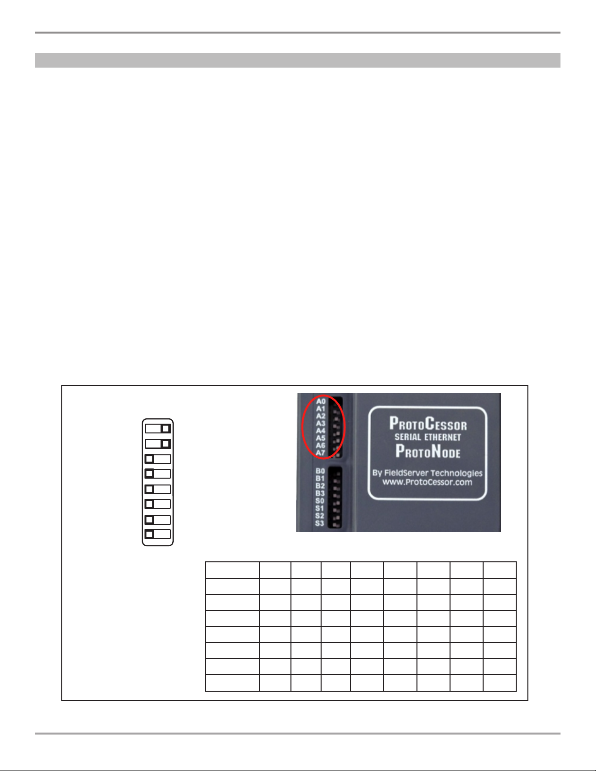
Appendix C. “A” Bank DIP Switch Settings ................................................................................................................ 26
Appendix C.1. “A” Bank DIP Switch Settings ............................................................................................................. 26
Appendix D. Limited 3-Year Warranty ......................................................................................................................... 29
1
1BACnet® and Metasys® are registered in the US Patent and Trademark Ofce

ET9500 Installation and Configuration Guide
— 4 —
1 INTRODUCTION
1.1 ET9500
ET9500 is an external, high performance multi-protocol interface box that is precongured to
automatically communicate between Intermatic ET90000 Series Time Switches (hereafter called
“device”) connected to the ET9500 and automatically congures them for BACnet®1MS/TP, BACnet®/
IP, Metasys®2N2 by JCI, Modbus TCP/IP or Modbus RTU.
It is not necessary to download any conguration les to support the required applications. The ET9500
is pre-loaded with tested Proles/Congurations for the supported devices.
NOTE: Network connection required.
Figure 1: System Configuration
1BACnet is a registered trademark of ASHRAE
2Metasys is a registered trademark of Johnson Controls Inc.

1 INTRODUCTION
— 5 —
1.2 DEVICES SUPPORTED
• The ET9500 supports 1,2,4,8,12 and 16 circuit ET90000’s.
• The total number of devices attached to one ET9500 cannot be more than 40 devices.
• See Figure 2 for Prole Name that correlates to the ET90000 installed.
Intermatic Part Number # of Circuits Profile Name
ET90115 1 …ET90115 01 Circuit
ET90215 2 …ET90215 02 Circuits
ET90415 4 …ET90415 04 Circuits
ET90815 8 …ET90815 08 Circuits
ET91215 12 …ET91215 12 Circuits
ET91615 16 …ET91615 16 Circuits
Figure 2: Devices Supported

ET9500 Installation and Configuration Guide
— 6 —
• Write down the IP Address for each of the ET90000 devices attached to the ET9500.
These addresses will be required for conguration in a later step below.
• Note the following:
o All of the ET90000 devices connected to ET9500 must be on the same IP
subnet.
o The PC that runs the Web Congurator must be on the same IP subnet. This is
the Web Server used to congure the ET9500.
2 COMMUNICATION PROTOCOL SETUP
2.1 Collecting ET90000’s IP Addresses
• ET9500 uses the “S” bank of DIP switches (S0 – S3) to select the Field Protocol.
• The default conguration is BACnet/IP (S0-S3 are off).
• If you have a different Protocol remove the white label (A0-7, B0-3, S0-3) to access DIP
switches.
NOTE: When setting DIP Switches, please ensure that power to the board is OFF.
• See Figure 3 for the switch settings to select BACnet MS/TP, BACnet/IP, Modbus TCP/
IP, Modbus RTU or Metasys N2.
• Set the DIP switches to the positions that match the Protocol required.
2.2 Selecting the Desired Field Protocol
S0
S1
S2
S3
ONOFF
S0 - S3 DIP
Switches
S Bank DIP Switches
Field Protocol S0 S1 S2 S3
BACnet/IP Off Off Off Off
BACnet MS/TP On Off Off Off
Modbus TCP/IP Off On Off Off
Modbus RTU On On Off Off
Metasys N2 Off Off On Off
S Bank DIP Switch Location
Figure 3: Switch Configuration for Field Protocol

2 COMMUNICATION PROTOCOL SETUP
— 7 —
• ET9500 uses the “B” bank of DIP switches (B0 – B3) to set the baud rate of the ET9500
to match the baud rate required by the BEMS for BACnet MS/TP or Modbus RTU.
• The default conguration is 38400 baud (B0,B1,B3 on and B2 off).
• If you have a different baud rate remove the white label (A0-7, B0-3, S0-3) to access
DIP switches.
NOTE: When setting DIP Switches, please ensure that power to the board is OFF.
• See Figure 4 for the switch settings to select 9600, 19200, 38400, 57600, 76800.
• Set the DIP switches to the positions that match the baud rate required.
2.3 Setting the Baud Rate (ONLY USED for BACnet MS/TP and Modbus RTU)
B0 - B3 DIP
Switches
Baud B0 B1 B2 B3
9600 On On On Off
19200 Off Off Off On
38400 On On Off On
57600 Off Off On On
76800 On Off On On
B Bank DIP Switch Location
Figure 4: Switch Configuration for Baud Rate
B0
B1
B2
B3
OFF ON

ET9500 Installation and Configuration Guide
— 8 —
• ET9500 uses the “A” bank of DIP switches (A0 – A7) to assign the MAC Address for the
ET9500.
• The default conguration is Address 3 (A0, A1 on and A2-7 off).
• If you need a different address remove the white label (A0-7, B0-3, S0-3) to access DIP
switches.
NOTE: When setting DIP Switches, please ensure that power to the board is OFF.
• Note the following:
o Only 1 MAC address is set for ET9500 regardless of how many devices are
connected to ET9500.
o Set the MAC address of the ET9500 to a value between 1 to 127 (Master MAC
address); this allows the BEMS Front End to nd ET9500 via BACnet auto
discovery.
o Note: Never set a BACnet MS/TP MAC Address of the ET9500 to a value from
128 to 255. Addresses from 128 to 255 are Slave Addresses and can not be
discovered by BEMS Front Ends that support Auto-Discovery of BACnet MS/
TP devices. This restriction does not apply to the Modbus RTU or Metasys N2.
• See Figure 5 for the switch settings to select Address. Please refer to Appendix C.1
for the complete range of MAC Addresses and DIP switch settings.
2.4 Setting the MAC Address (ONLY USED for BACnet MS/TP)
A0 - A7 DIP
Switches Address A0 A1 A2 A3 A4 A5 A6 A7
1 On Off Off Off Off Off Off Off
2Off On Off Off Off Off Off Off
3 On On Off Off Off Off Off Off
4Off Off On Off Off Off Off Off
5 On Off On Off Off Off Off Off
6Off On On Off Off Off Off Off
..
A Bank DIP Switch Location
Figure 5: Switch Configuration for MAC Address
A4
A5
A6
A7
ON
A0
A1
A2
A3
OFF

3 ET9500 NETWORK WIRE CONNECTIONS
— 9 —
• Connect the ET9500 using a standard CAT5 Ethernet cable via a hub, switch or router
to the connector on the bottom of ET9500 (see Figure 6).
NOTE:
• The ET90000’s MUST be installed and communicating on an Ethernet network.
• All connections need to be on the same subnet. (Section 4.1 & 4.3)
3.1 ET9500 Ethernet Connection to Network (For ET90000 and BEMS that uses Ethernet)
3 ET9500 NETWORK WIRE CONNECTIONS
Figure 6: Ethernet Connections
Ethernet Port
• Connect the ET9500 to the RS-485 network wires at the 3-pin RS-485 (Field) connector
on the top of ET9500 (see Figure 7).
o Connect RS-485+ and RS-485 – to Field connector.
o The RS-485 GND (Pin 3) is not typically connected.
3.2 ET9500 RS485 Connection to Network (For BEMS that uses RS485)
G+
BMS RS-485
Wiring
ProtoNode
Pin #
Pin
Assignment
+ Pin 1 RS-485 +
- Pin 2 RS-485 -
GND Pin 3 RS-485 GND
Figure 7: Connection from ET9500 to RS-485 Field Network
-
(Bottom View)

ET9500 Installation and Configuration Guide
— 10 —
• If the ET9500 is the last device, then the End-Of-Line Termination Switch needs to be
enabled (see Figure 8).
o Remove housing cover
• Pry top left or top right side outward to release cover latches.
o To enable the EOL Termination, turn the EOL switch ON (switch position = left
side).
o Install housing cover.
Figure 8: RS-485 EOL Switch
End-of-Line Switch
ON OFF

4 SETTING UP NETWORK SETTINGS
— 11 —
• Connect a standard Cat 5 Ethernet cable (Straight through or Cross-Over) between the
PC and ET9500.
• The Default IP Address of ET9500 is 192.168.1.24, Subnet Mask is 255.255.255.0. If
the PC and ET9500 are on different IP Networks, assign a static IP Address to the PC
on the 192.168.1.xxx network. NOTE: xxx cannot equal 24.
4.1 Setting PC Network IP for Windows XP
4 SETTING UP NETWORK SETTINGS
• Go to > >
• Right-click on Local Area Connection > Properties
• Highlight >
• Select: Use the following IP address
• Go to > >
> >
4.2 Setting PC Network IP for Windows 7
• Right-click on Local Area Connection > Properties
Highlight >
• Click twice
• For Windows XP and Windows 7, select: Use following IP address
• Click twice

ET9500 Installation and Configuration Guide
— 12 —
4.3 Setting IP Address for Field Network for BACnet/IP and Modbus TCP/IP
• Open a PC web browser, enter the default IP address of the ET9500 192.168.1.24 into
the URL eld to connect to the ET9500.
• To set IP Address for Field Network select the “Network Settings” Tab from the toolbar
(Figure 9).
• Modify the IP address (N1 IP Address eld) of the ET9500 Ethernet port.
• If necessary, change the Netmask (N1 Netmask eld).
• Type in a new Subnet Mask
• If necessary, change the IP Gateway (Default Gateway eld)
• Type in a new IP Gateway
Note: If the ET9500 is connected to a router, the IP Gateway of the ET9500 should be
set to the IP address of the router that it is connected to.
• Once new IP Address has been entered, click on the newly highlighted button “Update
Settings” (Figure 19).
• Reset ET9500
• Remove Power before Unplugging the Ethernet cable from PC and connecting it to the
network hub or router
• Record the IP address assigned to the ET9500 for future reference.
• After setting your PC to be on the same subnet as the ET9500 (Section 4.1), open a
web browser on your PC and enter the IP address of the ET9500; the default address
is 192.168.1.24.
4.4 Setting up the Device Instance using the Web Congurator
Figure 9: Changing IP Adress

4 SETTING UP NETWORK SETTINGS
— 13 —
4.4.1 Setting the Device Instance for BACnet/IP Network
• The BACnet Device Instances will be calculated by adding the Node_Offset (default
value is 90,000) to the unique device’s Node ID (See Section 5.2).
• The Node_Offset is found in the Web Congurator.
• The BACnet Device Instance can range from 1 to 4,194,303.
•
To assign specific Device Instance values, change the Node_Offset value.
(Section 5)
Example:
o Node_Offset value (default) = 90,000
o Device 1 has a unique Node-ID of 1
o Device 2 has a unique Node-ID of 22
o Device 3 has a unique Node-ID of 33
o Given that: Device Instance = Node_Offset + unique Node_ID
o Device Instance, Device 1 = 50,000 + 1 = 90,001
o Device Instance, Device 2 = 50,000 + 22 = 90,022
o Device Instance, Device 3 = 50,000 + 33 = 90,033
4.4.2 Setting the Device Instance for BACnet MS/TP Network
• The BACnet Device Instances will be calculated by adding the Node_Offset (default
value is 90,000) to the unique device’s Node ID (See Section 5.2).
• The Node_Offset is found in the Web Congurator.
• The BACnet Device Instance can range from 1 to 4,194,303.
•
To assign specific Device Instance values, change the Node_Offset value.
(Section 5)
Example:
o Node_Offset value (default) = 90,000
o Device 1 has a unique Node-ID of 1
o Device 2 has a unique Node-ID of 22
o Device 3 has a unique Node-ID of 33
o Given that: Device Instance = Node_Offset + unique Node_ID
o Device Instance, Device 1 = 50,000 + 1 = 90,001
o Device Instance, Device 2 = 50,000 + 22 = 90,022
o Device Instance, Device 3 = 50,000 + 33 = 90,033

ET9500 Installation and Configuration Guide
— 14 —
5.1 Start WEB Configurator Application
5 WEB CONFIGURATOR
• Type the IP address of the ET9500 into your web browser to open the WEB Congurator
Application.
• Once entered, screen below will be displayed.
5.2 Adding Profiles for Devices Connected to ET9500
• Each ET90000 connected to the ET9500 must have a device prole created. To add a
prole select the ‘Device’ Tab from the toolbar.
• The Active Proles section lists the currently active device proles, including previous
device additions. This list will be empty for new installations or after clearing all.
• To add an active prole to support a device, click the “+” button under Devices Tab.
Figure 10: Changing IP Adress
Figure 11: Changing IP Adress

5 WEB CONFIGURATOR
— 15 —
•
Type in a name for the device being added in the Device Name eld. Shown in Figure 12.
• Once device name has been entered, click the down arrow to select the Prole of
device connected. Shown in
Figure 13
.
• This will present a drop-down box underneath the Current Prole column that lists
all the available proles.
o Proles for supported devices will be offered in the drop-down box only for the
Field protocol option selected with the S bank of DIP switches in
Section 2.2
.
Figure 12: Naming a Device
Figure 13: Selecting Profile of Device
Figure 14: Specifying IP Address and Node-ID
• Specify the IP Address of the ET90000 device and unique Field Protocol Node-ID for
BACnet, Modbus and Metasys N2.
• The value of the device’s unique Node-ID is from 1 to 255.
• Do not re-use any ET9500 MAC adresses assigned with the “A” bank of DIP switches.

ET9500 Installation and Configuration Guide
— 16 —
• Enter the Scan Rate and Read Timeout.
• The Scan Rate is the interval at which the ET90000 device is scanned. Minimum value
is 2 seconds, maximum is 20 seconds; the default value is 10 seconds.
• Read Timeout is the time before an error is reported when no response is received.
Minimum value is 1 second, maximum is 10 seconds; the default value is 5 seconds.
Figure 15: Web Configurator Showing Node ID
• Press the Save button to add the Prole to the list of devices to be congured.
Figure 16: Web Configurator Showing Save Icon
• Repeat this process until all the devices have been added.
• Completed additions will be listed under Devices. Once all devices are added select
the ‘restart system’ icon to load the new conguration into the ET9500. See
Figure 17
.

5 WEB CONFIGURATOR
— 17 —
Figure 17: Web Configurator Showing System Restart to Load Configuration
Figure 18: BEMS Interface Settings

ET9500 Installation and Configuration Guide
— 18 —
6 HOW TO START THE INSTALLATION OVER: CLEARING THE PROFILES
• Check the proles you want to delete then click the “-“ icon to delete. See
Figure 19
.
Figure 19: BEMS Interface Settings
• Once restart is complete, all the devices that were added via the Web congurator will
be deleted. The unit is now ready to be reinstalled.

Appendix A. Troubleshooting
— 19 —
Appendix A.1. Viewing Diagnostic information
Appendix A. Troubleshooting
• Type the IP address of the ET9500 into your web browser.
• Click on “Diagnostics and Debugging” Icon , then click on view, and then on
connections.
• If there are any errors showing on the Connection page, please refer to Appendix A.2
for the relevant wiring and settings.
o If the Rx messages for the N1 Intermatic Ethernet connection are static go to
Appendix A.2
• No COMS on ET90000 device side: If Ethernet LED is not ashing then there is a COM
issue on the Ethernet side and you need to check the following things:
o Ethernet Cable
o Switch or Router
o All devices are on the same subnet as the ET9500 (See Section 4)
o Intermatic device IP setting match the Web conguration settings for that
device prole added
• Field COM problems:
o Visual dip switch settings (using correct baud rate, MAC address and Device
Instance)
o Verify IP address setting
o Verify wiring
Appendix A.2. Checking Wiring and Settings

ET9500 Installation and Configuration Guide
— 20 —
Appendix A.3. BACnet IP Settings
Appendix A.4. Setting up the ET9500 for BBMD on the BACnet/IP Network
On the main Web Congurator screen, update the BACnet details and hit the save icon.
Please note that the BACnet Network default value is 50.
The ET9500 is capable of being a BACnet BBMD Client on a BACnet network. When this
function is enabled, other BACnet networks on different subnets and other remote BACnet
networks can access the devices on the particular Subnet that the ET9500 is connected
to. Here are the steps to set up a BACnet BBMD Client:
• Create the bdt.ini le. You can get a sample bdt.ini le from Intermatic.
• Here is a format of the BDT.ini le to create:
// BBMD IP_Address , BBMD port , BBMD subnet Mask
24.90.48.179 , 47808 , 255.255.255.255
64.80.115.156 , 47808 , 255.255.255.255
• The last line of the bdt.ini le should be empty.
On the main Web Congurator screen, set the BACnet BBMD option to enable.
Figure 20: Web Configurator showing setting the network number for BACnet IP
Figure 21: Setting up the ET9500 for BBMD on the BACnet IP Network
• Click on the Diagnostics & Debugging button.
Other manuals for ET9500
1
Table of contents
Popular Network Hardware manuals by other brands

Cisco
Cisco CE 2000 Platform SCE 2000 4xGBE Installation and configuration guide

Moxa Technologies
Moxa Technologies AWK-6232-M12 installation guide

Allnet
Allnet ALL-MC116SV-VDSL2 user manual

Matrix Switch Corporation
Matrix Switch Corporation MSC-2HD2432L product manual

Newtec
Newtec NTC/2142 user manual

Bosch
Bosch VIP X1600 Module Quick installation guide

HP
HP 10:10 LAN Bridge MB Installation and reference guide

Western multiplex
Western multiplex Tsunami Multipoint Installation and maintenance manual

ADC
ADC Soneplex P-61-743 user manual

Spica
Spica Door Cloud Quick connection guide

Iomega
Iomega StorCenter ix12 user guide

DPS Telecom
DPS Telecom NetGuardian 16A user manual