Intermec 1284 User manual

Installation
Instructions
IEEE 1284 Parallel
Interface Kit
(for EasyCoder PF2i,
PF4i, PF4i Compact
Industrial, and PM4i)

Intermec Printer AB
Idrottsvägen 10
P.O. Box 123
S-431 22 Mölndal
Sweden
Service support: +46 31 869500
The information contained herein is proprietary and is provided solely
for the purpose of allowing customers to operate and/or service Intermec
manufactured equipment and is not to be released, reproduced, or used
for any other purpose without written permission of Intermec.
Information and specifications in this manual are subject to change
without notice.
© 2003 by Intermec Printer AB
All Rights Reserved
EasyCoder and Fingerprint are registered trademarks of Intermec Tech-
nologies Corp. The word Intermec and the Intermec logo are trademarks
of Intermec Technologies Corp.
The name Centronix is wholly owned by GENICOM Corporation.
Torx is a registered trademark of Camcar Division of Textron Inc.
Throughout this manual, trademarked names may be used. Rather than
put a trademark (™) symbol in every occurrence of a trademarked name,
we state that we are using the names only in an editorial fashion, and to
the benefit of the trademark owner, with no intention of infringement.

Preface
Contents
Introduction ................................................................................. iv
Printer Firmware........................................................................... iv
Installation Kit.............................................................................. iv
1 Physical Installation
EasyCoder PF2/4i printers .............................................................2
EasyCoder PM4i printers...............................................................7
2 Parallel Interface
Connector configuration..............................................................14
IEEE 1284 Parallel Interface Kit Installation Instructions iii

Preface
iv IEEE 1284 Parallel Interface Kit Installation Instructions
Introduction
This Installation Instructions booklet describes how to install an IEEE
1284 Parallel interface board in an EasyCoder PF2i, PF4i, PF4i Compact
Industrial, or PM4i printer.
The installation instructions describes how to physically install the
interface board in a printer and how to configure the two serial commu-
nication ports.
This interface kit must only be physically installed by an
authorized service technician. Intermec assumes no respon-
sibility for personal injury or damage to the equipment if
the installation in performed by an unauthorized person.
Take precautions against electrostatic discharges, for
example by wearing grounded bracelets.
Printer Firmware
The printer must be fitted with Intermec Fingerprint v8.00 (or later)
or IPL v2.00 (or later). In Intermec Fingerprint, the parallel port is
addressed as "centronics:" (communication channel #4).
Installation Kit
The IEEE 1284 Parallel Interface Kit contains:
• One IEEE 1284 parallel interface board.
• One hexagonal spacer (only used for two interface boards on a PM4i)
• Two flat cables
• One Installation Instruction booklet
The only tools required for the installation are #T10 and #T20 Torx
screwdrivers plus a small wrench.

IEEE 1284 Parallel Interface Kit Installation Instructions 1
1 Physical Installation
This chapter describes how to physically install the
IEEE 1284 parallel interface kit in a PF2/4i- or
PM4i-series printer.
2 IEEE 1284 Parallel Interface Kit Installation Instructions
Chapter 1 — Physical Installation
EasyCoder PF2/4i Printers
•Switch off the printer and disconnect the power cord.
•Disconnect all communication cables.
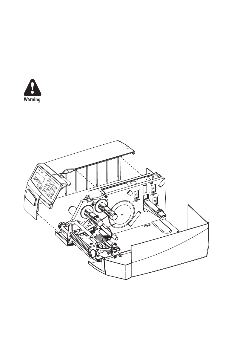
•Remove the front/left-hand cover as follows.
The electronic compartment contains wires and compo-
nents with dangerous voltage (up to 380V). Make sure that
the printer is switched off and the power cord is discon-
nected before the left-hand cover is removed.
•Open the right-hand door.
•Using a #T20 Torx screwdriver, remove the three screws and lift the
cover up so it disengages the bottom plate.
•Swing out the rear part of the cover so you can disconnect the console
cable from the CPU board.
•Put the cover aside on a soft cloth or similar to avoid scratches.
IEEE 1284 Parallel Interface Kit Installation Instructions 3
Chapter 1 —Physical Installation
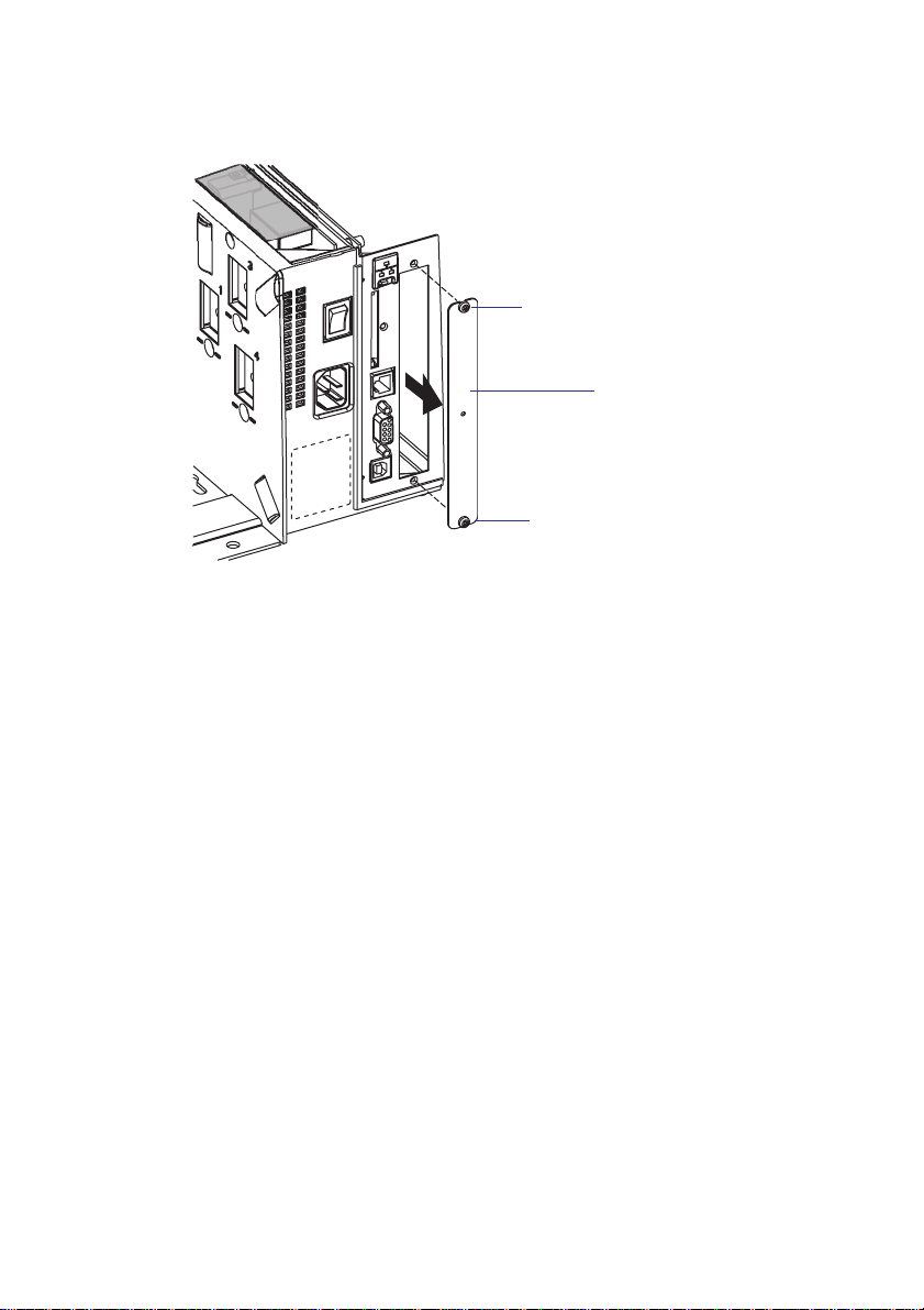
•Remove the two #T10 Torx screws that hold the interface cover plate.
Remove the cover plate.
•Save the cover plate for possible later use. Keep the screws.
•Remove the #T20 Torx screw fitted on the hexagonal spacer at the
center of the CPU board. Keep the screw.
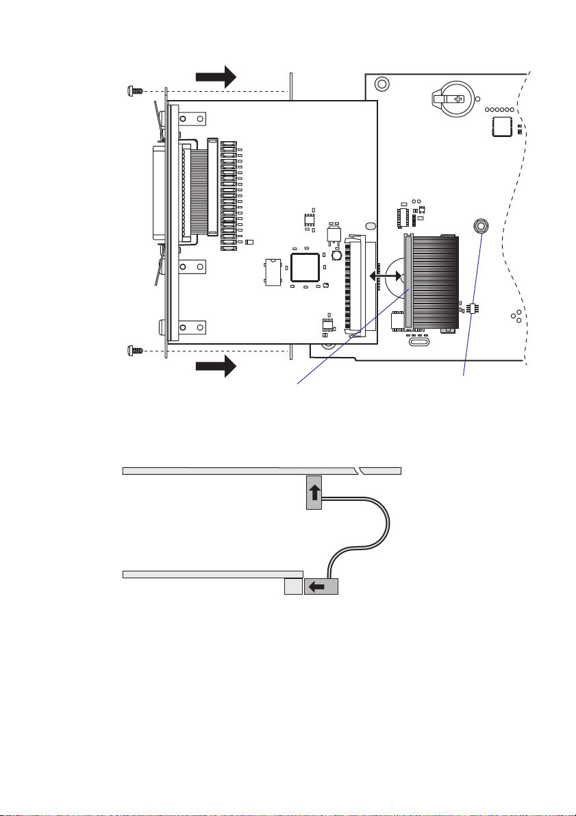
•Attach the flat cable included in the kit to connector J62 (marked
“EXP BOARD”) on the CPU board (see page 5).
#T10 Torx screw
Cover plate
#T10 Torx screw

4 IEEE 1284 Parallel Interface Kit Installation Instructions
Chapter 1 —Physical Installation
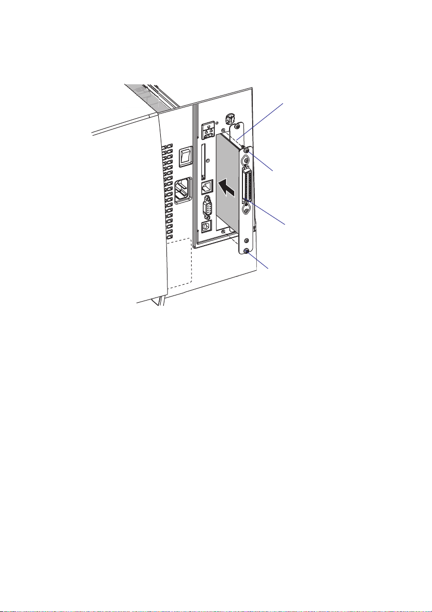
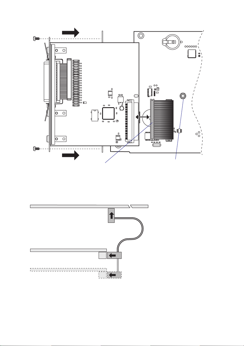
•Insert the interface board with the component side facing right, as
seen from behind.
•Attach the interface board to the printer’s rear plate using the two
screws left over when you removed the original cover plate.
•Using the #T20 Torx screw you previously removed, attach the inter-
face board to the hexagonal spacer you fitted on the CPU board.
•The kit contains two flat cables. Connect the flat cable with two con-
nectors to P1 on the interface board, see the next page.
Interface board
Component side
#T10 Torx screw
#T10 Torx screw
IEEE 1284 Parallel Interface Kit Installation Instructions 5
Chapter 1 —Physical Installation
•The flat cable should run as illustrated below.
Hexagonal
spacer
J61
P35
J62
EXP BOARD
C14
C2
C12
C13
C11
C9
C8
C3
C1
IC3
IC2
IC5
R19 R18
IC6
C10
C7
C6
C5
C4
IC1
R20
R22
R21
R17
R16
R15
R14
R13
R12
R8
R10
R11
F12
F11
F10
F18
F17
F16
F15
F14
F13
F8
F7
R3
R7
R6
R5
R4
R9
R2
R1
F19
F1
F2
F3
F9 D1
F6
F5
F4
IC4
P3
P1
1-971641-02 P01
P1
Cable
CPU Board
Interface Board
Cable

6 IEEE 1284 Parallel Interface Kit Installation Instructions
Chapter 1 —Physical Installation
•Connect the console cable to J50 on the CPU board and put back the
cover over the electronics compartment. Take care so the console cable
runs above the ribbon motor (if any) and does not become entangled
in the headlift mechanism.
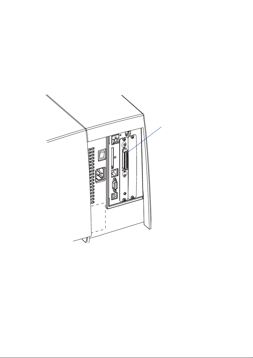
•Connect the communication cables to the connectors on the printer’s
rear plate.
•Connect the power cord and switch on the power.
Parallel interface

IEEE 1284 Parallel Interface Kit Installation Instructions 7
Chapter 1 —Physical Installation
EasyCoder PM4i Printers
•Switch off the printer and disconnect the power cord.
•Disconnect all communication cables.
•Turn the printer over so it rests on its left-hand cover. Use a soft cloth
or similar to avoid scratches.
•Open the right-hand door.
•Using a #T20 Torx screwdriver, remove the four screws that hold the
cover along the lower left edge of the bottom plate and the four screws
that hold the cover to the center section.
•Put the printer back on its feet and remove the cover while discon-
necting the console cable from the CPU board.
The electronic compartment contains wires and compo-
nents with dangerous voltage (up to 380V). Make sure that
the printer is switched off and the power cord is discon-
nected before the cover is removed.
•Put the cover aside taking care to avoid scratches.

8 IEEE 1284 Parallel Interface Kit Installation Instructions
Chapter 1 —Physical Installation
•Remove the two #T10 Torx screws that hold the inner interface cover
plate. Remove the cover plate.
•Save the cover plate for possible later use. Keep the screws.
•Remove the #T20 Torx screw fitted on the hexagonal spacer at the
center of the CPU board. Keep the screw.
•Attach the flat cable included in the kit to connector J62 (marked
“EXP BOARD”) on the CPU board (see illustration on page 10).
#T10 Torx screw
Cover plate
#T10 Torx screw
IEEE 1284 Parallel Interface Kit Installation Instructions 9
Chapter 1 —Physical Installation
•Insert the interface board with the component side facing right, as
seen from behind.
•Attach the interface board to the printer’s rear plate using the two
screws left over when you removed the original cover plate.
•Using the #T20 Torx screw you previously removed, attach the inter-
face board to the hexagonal spacer you fitted on the CPU board.
•The kit contains two flat cables, one with two connectors for use with
a single interface board and one with three connectors for use with
double interface boards. Connect the appropriate flat cable to connec-
tor P1 on the interface board, also see the next page.
Interface board
Component side
#T10 Torx screw
#T10 Torx screw
10 IEEE 1284 Parallel Interface Kit Installation Instructions
Chapter 1 —Physical Installation
•The flat cable should run as illustrated below.
•Put back the cover over the electronics compartment.
Hexagonal
spacer
J61
P35
J62
EXP BOARD
C14
C2
C12
C13
C11
C9
C8
C3
C1
IC3
IC2
IC5
R19 R18
IC6
C10
C7
C6
C5
C4
IC1
R20
R22
R21
R17
R16
R15
R14
R13
R12
R8
R10
R11
F12
F11
F10
F18
F17
F16
F15
F14
F13
F8
F7
R3
R7
R6
R5
R4
R9
R2
R1
F19
F1
F2
F3
F9 D1
F6
F5
F4
IC4
P3
P1
1-971641-02 P01
P1
Cable
CPU Board
Inner Interface Board
(Outer Interface Board)
Cable
IEEE 1284 Parallel Interface Kit Installation Instructions 11
Chapter 1 —Physical Installation
•Connect the console cable to J50 on the CPU board and put back the
cover over the electronics compartment. Take care so the console cable
runs above the ribbon motor and does not become entangled in the
headlift mechanism.
•Connect the power cord and switch on the power.
Parallel interface

12 IEEE 1284 Parallel Interface Kit Installation Instructions
Chapter 1 —Physical Installation
Double Interface Boards
If you need to install two interface boards, first install the inner board,
then the outer one using the same flat cable from one of the kits. Put
the hexagonal spacer included in the kit between the inner and the outer
interface board. The list below shows which combinations are allowed
and how the ports will be designated in Fingerprint.
Allowed interface combinations (Fingerprint only)
Left-hand slot Ports Right-hand slot Ports
Double Serial uart2: + uart3: ––
Double Serial uart2: + uart3: IEEE 1284 centronics:
Serial/Industrial uart2: ––
Serial/Industrial uart2: Serial/Industrial uart3:
Serial/Industrial uart2: IEEE 1284 centronics:
IEEE 1284 centronics: ––
IEEE 1284 centronics: Double Serial uart2: + uart3:
IEEE 1284 centronics: Serial/Industrial uart2:
Remarks:
•The left-hand slot is the slot closest to the center section.
•Always start by fitting an interface board in the left-hand slot.
•RS-485 is only supported by "uart2:"
•IPL does not support double interface boards. Always install the IEEE
1284 parallel interface board in the innermost slot.

IEEE 1284 Parallel Interface Kit Installation Instructions 13
2 Parallel Interface
This chapter describes the signals on the connector of
the IEEE 1284 interface board.
Note: Nibble, byte, ECP, and EPP modes
from printer to host are presently not sup-
ported.

14 IEEE 1284 Parallel Interface Kit Installation Instructions
Chapter 2 —Parallel Interface
Connector Configuration
The IEEE 1284 board has a standard 36pin IEEE 1284 B socket with
the following configuration:
Pin Signal Remark
1 DSTROBE
2 DATA 0
3 DATA 1
4 DATA 2
5 DATA 3
6 DATA 4
7 DATA 5
8 DATA 6
9 DATA 7
10 ACK
11 BUSY
12 PE
13 SELECT
14 AF
15 N/C Not connected
16 GND
17 SCREEN
18 . External +5VDC max 500 mA (automatic switch-off at over-
load, short-circuit protected)
19-30 GND
31 INIT
32 ERROR
33-35 N/C Not connected
36 SELECTIN


Intermec Printer AB
Idrottsvägen 10, P.O. Box 123
S-431 22 Mölndal, Sweden
tel +46 31 869500
fax +46 31 869595
www.intermec.com
*1-960593-00*
IEEE 1284 Parallel Interface Kit Installation Instructions
*1-960593-00*
Table of contents
Other Intermec Recording Equipment manuals


