International comfort products N9MP1 User manual
ÉÉÉ
ÉÉÉ
ÉÉÉ
ÉÉÉ
ÉÉÉ
ÉÉÉ
ÉÉÉ
ÉÉÉ
ÉÉÉ
ÉÉÉ
ÉÉÉ
ÉÉÉ
ÉÉÉ
ÉÉ
ÉÉ
ÉÉ
ÉÉ
ÉÉÉ
ÉÉÉ
ÉÉÉ
ÉÉÉ
ÉÉÉ
ÉÉÉ
ÉÉÉÉ
ÉÉÉÉ
ÉÉÉÉ
ÉÉÉÉ
ÉÉÉ
ÉÉÉ
ÉÉÉ
ÉÉÉÉ
ÉÉÉÉ
ÉÉÉÉ
ÉÉÉ
ÉÉÉ
ÉÉÉ
ÉÉÉ
ÉÉÉ
ÉÉÉ
ÉÉ
ÉÉ
ÉÉ
ÉÉ
MULTI POSITION
90% SINGLE STAGE
GAS FURNACES
Part Number
440 08 2011 00
N9MP1, N9MP2 & *9MPD
* Denotes brand H, C, T
Manufactured by:
This manual supports single stage “C” series and later condensing gas furnaces
©2006 International Comfort Products LLC
ÁÁÁÁÁÁÁÁÁÁÁÁÁÁÁÁÁÁÁÁÁÁÁÁÁÁÁÁ
ÁÁÁÁÁÁÁÁÁÁÁÁÁÁÁÁÁÁÁÁÁÁÁÁÁÁÁÁ
ÁÁÁÁÁÁÁÁÁÁÁÁÁÁÁÁÁÁÁÁÁÁÁÁÁÁÁÁ
ÁÁÁÁÁÁÁÁÁÁÁÁÁÁÁÁÁÁÁÁÁÁÁÁÁÁÁÁ
ÁÁÁÁÁÁÁÁÁÁÁÁÁÁÁÁÁÁÁÁÁÁÁÁÁÁÁÁ
ÁÁÁÁÁÁÁÁÁÁÁÁÁÁÁÁÁÁÁÁÁÁÁÁÁÁÁÁ
ÁÁÁÁÁÁÁÁÁÁÁÁÁÁÁÁÁÁÁÁÁÁÁÁÁÁÁÁ
ÁÁÁÁÁÁÁÁÁÁÁÁÁÁÁÁÁÁÁÁÁÁÁÁÁÁÁÁ
ÁÁÁÁÁÁÁÁÁÁÁÁÁÁÁÁÁÁÁÁÁÁÁÁÁÁÁÁ
2/2006

N9MP1 −Indoor combustion air (1 pipe only)
N9MP2 −Direct Vent ONLY (2 pipe only)
*9MPD −Dual Certified Venting (1 or 2 pipes)
* Denotes Brand (T, C or H)

Service Manual
Single Stage Multi Position Furnace
TABLE OF CONTENTS
1. INTRODUCTION 2. . . . . . . . . . . . . . . . . . . . . . . . . . . . . . . . . . . . . . . . . . . . . . . . . . . . . . . . . . . .
2. UNIT IDENTIFICATION 3. . . . . . . . . . . . . . . . . . . . . . . . . . . . . . . . . . . . . . . . . . . . . . . . . . . . .
3. FURNACE THEORY OF OPERATION 3. . . . . . . . . . . . . . . . . . . . . . . . . . . . . . . . . . . . . . . .
4. ELECTRICAL SUPPLY 4. . . . . . . . . . . . . . . . . . . . . . . . . . . . . . . . . . . . . . . . . . . . . . . . . . . . . .
5. INTERLOCK SWITCH 5. . . . . . . . . . . . . . . . . . . . . . . . . . . . . . . . . . . . . . . . . . . . . . . . . . . . . .
6. GAS SUPPLY 5. . . . . . . . . . . . . . . . . . . . . . . . . . . . . . . . . . . . . . . . . . . . . . . . . . . . . . . . . . . . . .
7. L.P. PRESSURE SWITCH 10. . . . . . . . . . . . . . . . . . . . . . . . . . . . . . . . . . . . . . . . . . . . . . . . . . .
8. HONEYWELL VR8205S GAS VALVE 11. . . . . . . . . . . . . . . . . . . . . . . . . . . . . . . . . . . . . . . . .
9. HIGH ALTITUDE OPERATION 11. . . . . . . . . . . . . . . . . . . . . . . . . . . . . . . . . . . . . . . . . . . . . . .
10. CHECKING TEMPERATURE RISE 11. . . . . . . . . . . . . . . . . . . . . . . . . . . . . . . . . . . . . . . . . .
11. ROOM THERMOSTATS 12. . . . . . . . . . . . . . . . . . . . . . . . . . . . . . . . . . . . . . . . . . . . . . . . . . . .
12. CONTROL WIRING 12. . . . . . . . . . . . . . . . . . . . . . . . . . . . . . . . . . . . . . . . . . . . . . . . . . . . . . .
13. TWINNING KITS 13. . . . . . . . . . . . . . . . . . . . . . . . . . . . . . . . . . . . . . . . . . . . . . . . . . . . . . . . . .
14. LIMIT SWITCHES 13. . . . . . . . . . . . . . . . . . . . . . . . . . . . . . . . . . . . . . . . . . . . . . . . . . . . . . . . .
15. PRESSURE SWITCHES 14. . . . . . . . . . . . . . . . . . . . . . . . . . . . . . . . . . . . . . . . . . . . . . . . . . .
16. HIGHER/LOWER NEGATIVE PRESSURES 16. . . . . . . . . . . . . . . . . . . . . . . . . . . . . . . . . .
17. VENT/COMBUSTION AIR PIPING 17. . . . . . . . . . . . . . . . . . . . . . . . . . . . . . . . . . . . . . . . . .
18. STANDARD VENT TERMINATION 17. . . . . . . . . . . . . . . . . . . . . . . . . . . . . . . . . . . . . . . . . .
19. CONCENTRIC VENT TERMINATION 21. . . . . . . . . . . . . . . . . . . . . . . . . . . . . . . . . . . . . . . .
20. COMBUSTION BLOWER 22. . . . . . . . . . . . . . . . . . . . . . . . . . . . . . . . . . . . . . . . . . . . . . . . . .
21. CONDENSATE DRAIN TRAP 23. . . . . . . . . . . . . . . . . . . . . . . . . . . . . . . . . . . . . . . . . . . . . . .
22. SEQUENCE OF OPERATION 24. . . . . . . . . . . . . . . . . . . . . . . . . . . . . . . . . . . . . . . . . . . . . .
23. CHECKING FLAME CURRENT 26. . . . . . . . . . . . . . . . . . . . . . . . . . . . . . . . . . . . . . . . . . . . .
24. CAPACITORS 26. . . . . . . . . . . . . . . . . . . . . . . . . . . . . . . . . . . . . . . . . . . . . . . . . . . . . . . . . . . .
25. BLOWER ASSEMBLY 26. . . . . . . . . . . . . . . . . . . . . . . . . . . . . . . . . . . . . . . . . . . . . . . . . . . . .
BLOWER PERFORMANCE DATA 29. . . . . . . . . . . . . . . . . . . . . . . . . . . . . . . . . . . . . . . . . . . . . .
WIRING DIAGRAM 30. . . . . . . . . . . . . . . . . . . . . . . . . . . . . . . . . . . . . . . . . . . . . . . . . . . . . . . . . . .
TECHNICAL SERVICE DATA (N9MP1 C1) 31. . . . . . . . . . . . . . . . . . . . . . . . . . . . . . . . . . . . . . .
TECHNICAL SERVICE DATA (N9MP2 C1) 32. . . . . . . . . . . . . . . . . . . . . . . . . . . . . . . . . . . . . . .
TECHNICAL SERVICE DATA (*9MPD C1) 33. . . . . . . . . . . . . . . . . . . . . . . . . . . . . . . . . . . . . .
TROUBLE SHOOTING GUIDE 34. . . . . . . . . . . . . . . . . . . . . . . . . . . . . . . . . . . . . . . . . . . . . . . . .
DIAGNOSTIC CODE SECTION 35. . . . . . . . . . . . . . . . . . . . . . . . . . . . . . . . . . . . . . . . . . . . . . . .
TROUBLE SHOOTING CHART #1 36. . . . . . . . . . . . . . . . . . . . . . . . . . . . . . . . . . . . . . . . . . . . . .
TROUBLE SHOOTING CHART #2 37. . . . . . . . . . . . . . . . . . . . . . . . . . . . . . . . . . . . . . . . . . . . . .
TROUBLE SHOOTING CHART #3 38. . . . . . . . . . . . . . . . . . . . . . . . . . . . . . . . . . . . . . . . . . . . . .
INDEX 40. . . . . . . . . . . . . . . . . . . . . . . . . . . . . . . . . . . . . . . . . . . . . . . . . . . . . . . . . . . . . . . . . . . . . .
Single Stage Multi Position Furnace
Service Manual
440 08 2011 00
4
INTRODUCTION
This service manual is designed to be used in conjunction
with the installation manual and/or technical support manu-
al provided with each furnace.
These furnaces represent the very latest in high efficiency
gas furnace technology. Consequently, they incorporate
the use of certain controls that contain highly sophisticated
electronic components which are not user serviceable.
Therefore, it is essential that only competent, qualified, ser-
vice personnel attempt to install, service, or maintain this
product.
This Service manual was written to assist the professional
HVAC service technician to quickly and accurately diag-
nose and repair any malfunction of this product.
This service manual covers the following models;
*9MPD−−−−−−C or later, *9MP1 −−−−−−C or
later and *9MP2 −−−−−−C or later models. The overall
operation of all of these models is essentially the same.
This manual, therefore, will deal with all subjects in a gener-
al nature (I.E. all text will pertain to all models) unless that
subject is unique to a particular model or family, in which
case it will be so indicated.
It will be necessary then for you to accurately identify the
unit you are servicing, so you may be certain of a proper
diagnosis and repair. (See Unit Identification, Page 3)
SAFETY REQUIREMENTS
Recognize safety information. This is the safety−alert symbol . When you see this symbol on the furnace and in instructions manuals be alert to
the potential for personal injury.
Understand the signal words DANGER, WARNING, or CAUTION. These words are used with the safety−alert symbol. DANGER identifies the most
serious hazards, those that will result in severe personal injury or death. WARNING signifies a hazard that could result in personal injury or death.
CAUTION is used to identify unsafe practices that could result in minor personal injury or product and property damage. NOTE is used to highlight
suggestions that will result in enhanced installation, reliability, or operation.
Installing and servicing heating equipment can be hazardous due to gas and electrical components. Only trained and qualified personnel should
install, repair, or service heating equipment.
Untrained service personnel can perform basic maintenance functions such as cleaning and replacing air filters. All other operations must be per-
formed by trained service personnel. When working on heating equipment, observe precautions in the literature, on tags, and on labels attached to or
shipped with the unit and other safety precautions that may apply.
Follow all safety codes. In the United States, follow all safety codes including the current edition National Fuel Gas Code (NFGC) ANSI
Z223.1−2002/NFPA No. 54−2002. In Canada, refer to the current edition of the National Standard of Canada Natural Gas and Propane Installation
Code (NSCNGPIC) CSA B149.1−05. Wear safety glasses and work gloves. Have fire extinguisher available during start−up and adjustment proce-
dures and service calls.
These instructions cover minimum requirements and conform to existing national standards and safety codes. In some instances, these instructions
exceed certain local codes and ordinances, especially those that may not have kept up with changing residential construction practices. We require
these instructions as a minimum for a safe installation.
!
cInternational Comfort Products LLC
Lewisburg, TN 37091
Single Stage Multi Position Furnace Service Manual
440 08 2011 00 5
UNIT IDENTIFICATION
The unit’s rating plate contains important information for the
service technician. It also lists the complete Model
Manufacturing and Serial Numbers.
These complete numbers are required to obtain correct re-
placement parts (example, in certain model families a unit
having a MARKETING REVISION of “C” is likely to be
equipped with one or more different components.
MODEL NUMBER IDENTIFICATION GUIDE
* 9M P D0 75 B1 2 C 1
Brand Identifier Engineering Rev.
T = Tempstar Denotes major changes
C = Comfortmaker Marketing Digit
H = Heil Denotes major change
A = Arcoaire
N = Non−Brand Specific (Generic) Cooling Airflow
Brand Identifier 08 = 800 CFM
8 = Non−Condensing, 80+% Gas Furnace 12 = 1200 CFM
9 = Condensing, 90+% Gas Furnace 14 = 1400 CFM
Installation Configuration 16 = 1600 CFM
UP = Upflow DN = Downflow UH = Upflow/Horizontal 20 = 2000 CFM
HZ = Horizontal DH = Downflow/Horizontal
MP = Multiposition, Upflow/Downflow/Horizontal Cabinet Width
Major Design Feature B = 15.5″Wide
1 = One (Single) Pipe N = Single Stage F = 19.1″Wide
2 = Two Pipe P = PVC Vent J = 22.8″Wide
D = 1 or 2 Pipe T = Two Stage L = 24.5″Wide
L = Low NOx V = Variable Speed Input (Nominal MBTUH)
FURNACE THEORY OF OPERATION
The high efficiencies and lower profile (compared to past
series) of this furnace have been obtained using design
techniques not typical of traditional furnace designs. A brief
description of these new design techniques and the pur-
pose they serve follows.
1. Reducing the height of the furnace while maintaining
the high efficiency of pervious models required main-
taining the surface area of the heat exchanger and
yet minimizing the overall size.
The design required to achieve these results is the “SER-
PENTINE” design, wherein the flue gasses must follow a
serpent shaped passage through the heat exchanger via
convection.
This “Serpentine” path is resistive to normal convective
flow, and requires that a partial vacuum be created at the
outlet of the heat exchanger to maintain the flow of flue
products through the heat exchanger.
2. The serpentine heat exchanger design does not lend
itself well to the ribbon type, or slotted port type burner
found in more traditional design furnaces for the fol-
lowing reasons:
A. The secondary combustion airflows at right angles
to the burner flame, making it likely to “pull” the
flame off a ribbon or slotted port type burner.
B. The flame “height” of a ribbon or slotted port type
burner would make it difficult (if not impossible) to
prevent impingement of the flame on the heat ex-
changer surfaces whole maintaining the low profile
heat exchanger.
For these reasons, an “INSHOT” type burner is used in this
series. The inshot burner (also called a “jet” burner) fires a
flame straight out its end. This burner is designed to fire into
a tube style heat exchanger, making it an ideal application
in the tube−like passages of the serpentine heat exchanger.
3. In order to extract the maximum amount of heat pos-
sible from the flue gasses, a secondary heat ex-
changer (condenser) is connected to the outlet of the
primary heat exchanger. This condenser removes
additional heat from the flue gasses, causing their
temperature to drop below dew point. This results in
the forming of condensation (water) which then must
be routed to a drain.
4. The placement of the secondary heat exchanger at
the outlet of the primary heat exchanger creates addi-
tional resistance to the flow of gasses.
5. To overcome the resistance to convective flow of the
Primary and Secondary heat exchangers requires the
use of an Induced Draft Combustion Blower Assem-
bly.
Single Stage Multi Position Furnace
Service Manual
440 08 2011 00
6
6. The Combustion Blower Assembly is mounted on the
outlet side of the Secondary heat exchanger, This
blower creates a partial vacuum (negative pressure)
within the heat exchangers drawing the flue products
out of the furnace.
7. A pressure switch (Air Proving Switch) is used as a
safety device that prevents the ignition system from
firing the furnace until it senses that a proper draft has
been established through the furnace.
SEQUENCE OF OPERATION − HEATING
Refer to the ignition control section for sequence of opera-
tion.
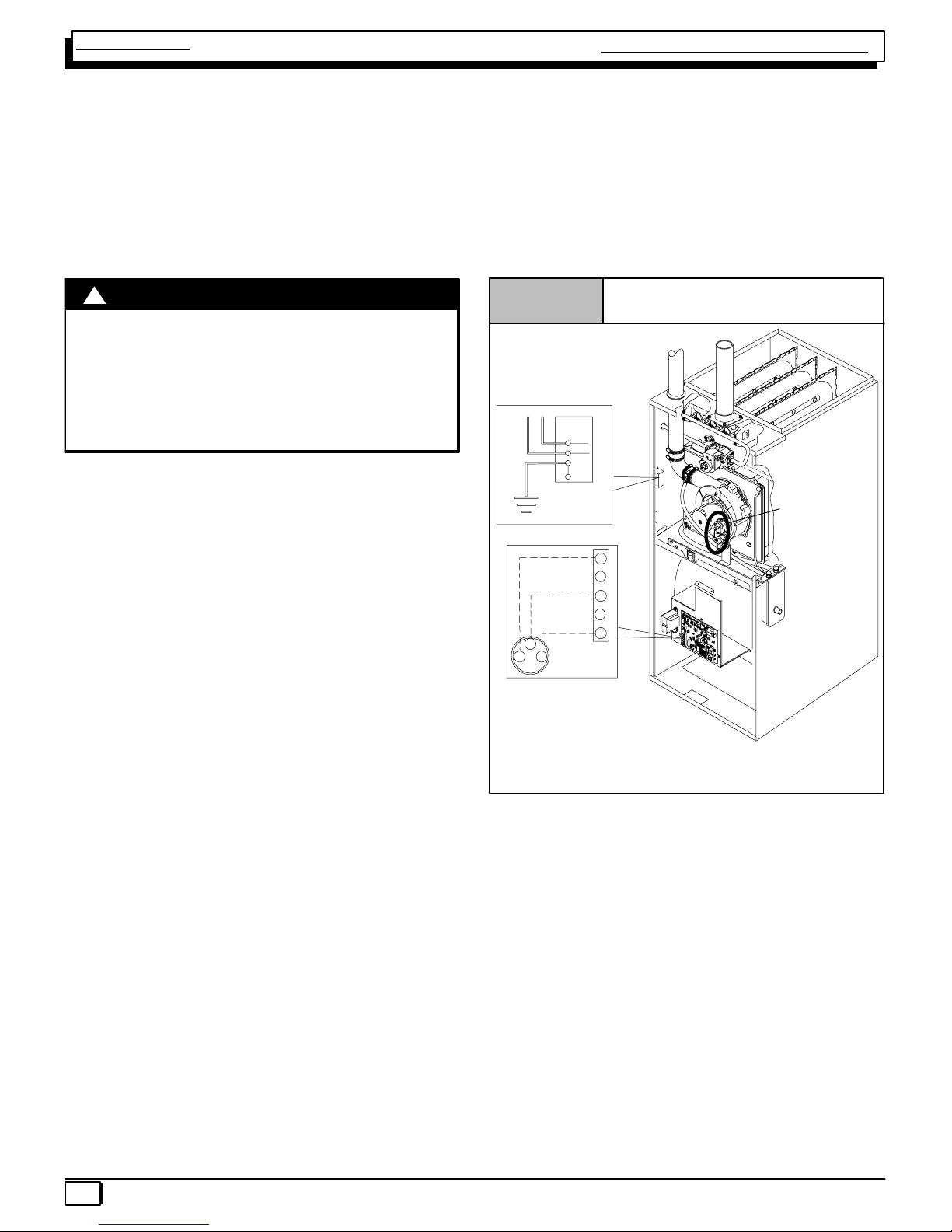
ELECTRICAL SUPPLY
ELECTRICAL SHOCK HAZARD.
Failure to turn off power could result in death or
personal injury.
Turn OFF electrical power at fuse box or service
panel before making any electrical connections
and ensure a proper ground connection is made
before connecting line voltage.
!WARNING
SUPPLY CIRCUIT
The furnace cannot be expected to operate correctly unless
it is properly connected (wired) to an adequately sized
single branch circuit. Line voltage wires should conform to
temperature limitation of 63°F (35°C) rise and be sized for
the unit maximum amps stated on the rating plate. Add the
full load amps for potential field −installed accessories that
would receive power from the furnace control. Consult NEC
or local codes for proper wire and circuit sizing.
SUPPLY VOLTAGE
Supply voltage to the furnace should be a nominal 115 volts.
It MUST be between 104 volts and 127 volts. Supply volt-
age to the furnace should be checked WITH THE FUR-
NACE IN OPERATION. Voltage readings outside the speci-
fied range can be expected to cause operating problems.
Their cause MUST be investigated and corrected.
ELECTRICAL GROUND
Proper grounding of the electrical supply to THE FURNACE
IS REQUIRED for safety and operational reasons.
POLARITY
CORRECT POLARITY of the line voltage supply to the fur-
nace is also required for safety and operational reasons.
The furnace control MUST have proper line voltage polarity
to operate properly.
NOTE: Junction Box can be
mounted to either the left or right
side.
25−24−90−2
Models may
have 1 or 2
pressure
switches
NOTE: 115 VAC/60Hz/single−phase
Operating voltage range*: 127 VAC max, 104 VAC min.
* Permissible limits of voltage at which unit will operate satisfactorily
115V. 60 Hz
W
W
W
Low Voltage
Terminal Board
R
R
BK
Ground
Connection
Box
G
HOT
NEUT.
G
G
Y
G
O
N
O
FF
Figure 1 Electrical Connections
CHECKING GROUNDING AND POLARITY
Grounding may be verified as follows:
1. Turn the power supply “OFF”.
2. Using an Ohmmeter check for continuity between the
Neutral (white) wire and Ground wire (green) of the
supply circuit.
3. With the Ohmmeter set on the R x 1 scale, the read-
ing should be zero Ohms.
4. A zero Ohm reading indicates that the neutral is
grounded back to the main panel.
Single Stage Multi Position Furnace Service Manual
440 08 2011 00 7
5. An alternate check would be to check for continuity
from the Neutral to a cold water pipe, (Pipe must be
metal, and must have a continuous, uninterrupted
connection to ground) or to a continuous, uninter-
rupted connection to ground) or to a driven ground
rod.
6. Any readings other than zero Ohms would indicate
a poor ground, or no ground.
Polarity may be verified as follows:
1. Turn the power supply “ON”.
2. Using a Voltmeter check for voltage between the Hot
(Black) and Neutral (White) wire of supply circuit.
3. Reading should be Line (Supply) Voltage.
4. Check for Voltage between the Neutral (White) wire
and Ground wire of the supply circuit.
5. Reading should be zero Volts. (if line voltage is read,
polarity is reversed)
6. A zero Volt reading indicates there is no voltage po-
tential on Neutral wire.
7. Double check by checking for voltage between the
Hot (Black) wire and Ground wire of the supply cir-
cuit.
8. Reading should be Line (supply) Voltage. (if zero
volts is read, there is no ground, or polarity is re-
versed.)
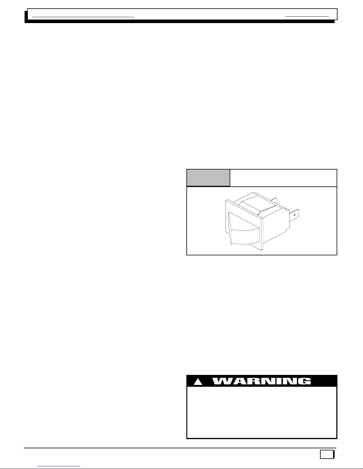
INTERLOCK SWITCH
The blower compartment door of all models is equipped
with an interlock switch. (See Figure 2) This switch is “Nor-
mally Open” (closes when the door is on the furnace) and
interrupts furnace operation when the door is open. This in-
terlock switch is a safety device, and SHOULD NEVER BE
BY−PASSED.
Since this is a single pole switch, (breaking only one side of
the line) proper line polarity is essential to insure that fur-
nace components are not “HOT” when switch is open. (See
Checking Grounding and Polarity)
Figure 2 Typical Interlock Switch
10−12−96
GAS SUPPLY
An adequately sized gas supply to the furnace is required
for proper operation. Gas piping which is undersized will not
provide sufficient capacity for proper operation. Piping
should be sized in accordance with accepted industry stan-
dards. Refer to NFGC and ANSI Z223.1 for proper gas pipe
size.
NATURAL GAS
Inlet (Supply) pressure to the furnace should be checked (at
the gas valve) with ALL OTHER GAS FIRED APPLIANCES
OPERATING. Inlet (Supply) pressure to the furnace under
these conditions MUST be within minimum and maximum
values listed on rating plate. If the inlet pressure is less, it
may be an indication of undersized piping or regulator prob-
lems.
L.P. GAS
Inlet (Supply) pressure to the furnace should be checked in
the same manner as for Natural Gas, however with L.P.
Gas, the inlet pressure MUST be a minimum of 11″W.C. If
this cannot be obtained, problems are indicated in either the
regulator or pipe sizing.
CHECKING INPUT (FIRING) RATE
Once it has been determined that the gas supply is correct
to the furnace, it is necessary to check the input (firing) rate.
This can be done in two (2) ways. First by checking and ad-
justing (as necessary) the manifold (Outlet) pressure. The
second way is to “Clock” the gas meter.
FIRE OR EXPLOSION HAZARD.
Turn OFF gas at shut off before connecting
manometer.
Failure to turn OFF gas at shut off before
connecting manometer can result in death,
personal injury and/or property damage.
!

Single Stage Multi Position Furnace
Service Manual
440 08 2011 00
8
Gas Pressure Testing Devices
Figure 3
MAGNEHELIC
MAX. PRESSURE 15 PSIG
0
510
15
INCHES OF WATER
Pressure Connections
Typical U" Tube
Manometer
7
6
5
7
6
5
3
4
4
0
3
2
2
1
1
CHECKING MANIFOLD PRESSURE
NOTE: Make adjustment to manifold pressure with burners
operating.
1. Remove the burner compartment door.
2. With gas OFF, connect manometer to outlet tapped
opening on gas valve. Use manometer with a 0 to 15″
water column range.
3. Turn gas on. Remove the blower compartment door.
Operate the furnace by jumpering Rto Won the fur-
nace control board.
4. Remove manifold pressure adjustment screw cover
on furnace gas control valve. Turn adjusting screw
counterclockwise to decrease manifold pressure and
clockwise to increase pressure.
VT
25−24−98a
HONEYWELL
ON
OFF
Typical Gas Control Valve Honeywell
Figure 4
Manifold Regulator
Adjustment
Under Cap
Inlet
Pressure
Tap 1/8NPT
INLET
OUTLET
Outlet
Pressure
Tap
1/8NPT
NOTE: Adjustment screw cover MUST be replaced on gas
control valve before reading manifold pressure and operat-
ing furnace.
5. Obtain gas heating value and installation site altitude.
6. Set manifold pressure to value shown in Table 2,
Table 3, Table 4 or Table 5.
7. When the manifold pressure is properly set, replace
the adjustment screw cover on the gas control valve.
8. Remove jumper wire from thermostat connection on
furnace control board. Remove manometer connec-
tion from manifold pressure tap, and replace plug in
valve.
9. Check for leaks at plug.
10. Replace the burner compartment and blower
compartment door.
Natural Gas Input Rating Check
NOTE: The gas meter can be used to measure input to fur-
nace. Rating is based on a natural gas BTU content of 1,000
BTU’s per cubic foot. Check with gas supplier for actual
BTU content.
1. Make sure burner compartment door is in place be-
fore performing the following steps.
2. Turn OFF gas supply to all appliances and start fur-
nace.
Example
Natural Gas
BTU Content
No. of Seconds
Per Hour
Time Per Cubic
Foot in Seconds
BTU Per
Hour
1,000 3,600 48 75,000
1,000 x 3,600 ÷48 = 75,000 BTUH
3. Time how many seconds it takes the smallest (nor-
mally 1 cfh) dial on the gas meter to make one com-
plete revolution. Refer to Example.
4. Relight all appliances and ensure all pilots are operat-
ing.
NOTE: If meter uses a 2 cubic foot dial, divide results (sec-
onds) by two.
Alternate BTUH Input Ratings (USA Only)
The input rating of these furnaces can be changed from the
standard input rating to the alternate input rating shown in
Table 1, by changing the main burner orifices. Changing of
burner orifices MUST be done by a qualified service techni-
cian. See section on changing orifices on page 9.
Table 1 Alternate Input Ratings, USA ONLY.
BTUH
Standard
Rating
BTUH
Alternate
Rating
Natural
Gas
Orifice*
LP
Gas
Orifice**
50,000 40,000 #44 #55
75,000 60,000 #44 #55
100,000 80,000 #44 #55
125,000 100,000 #44 #55
* See Table 4 for High Altitude.
** See Table 5 for High Altitude

Single Stage Multi Position Furnace Service Manual
440 08 2011 00 9
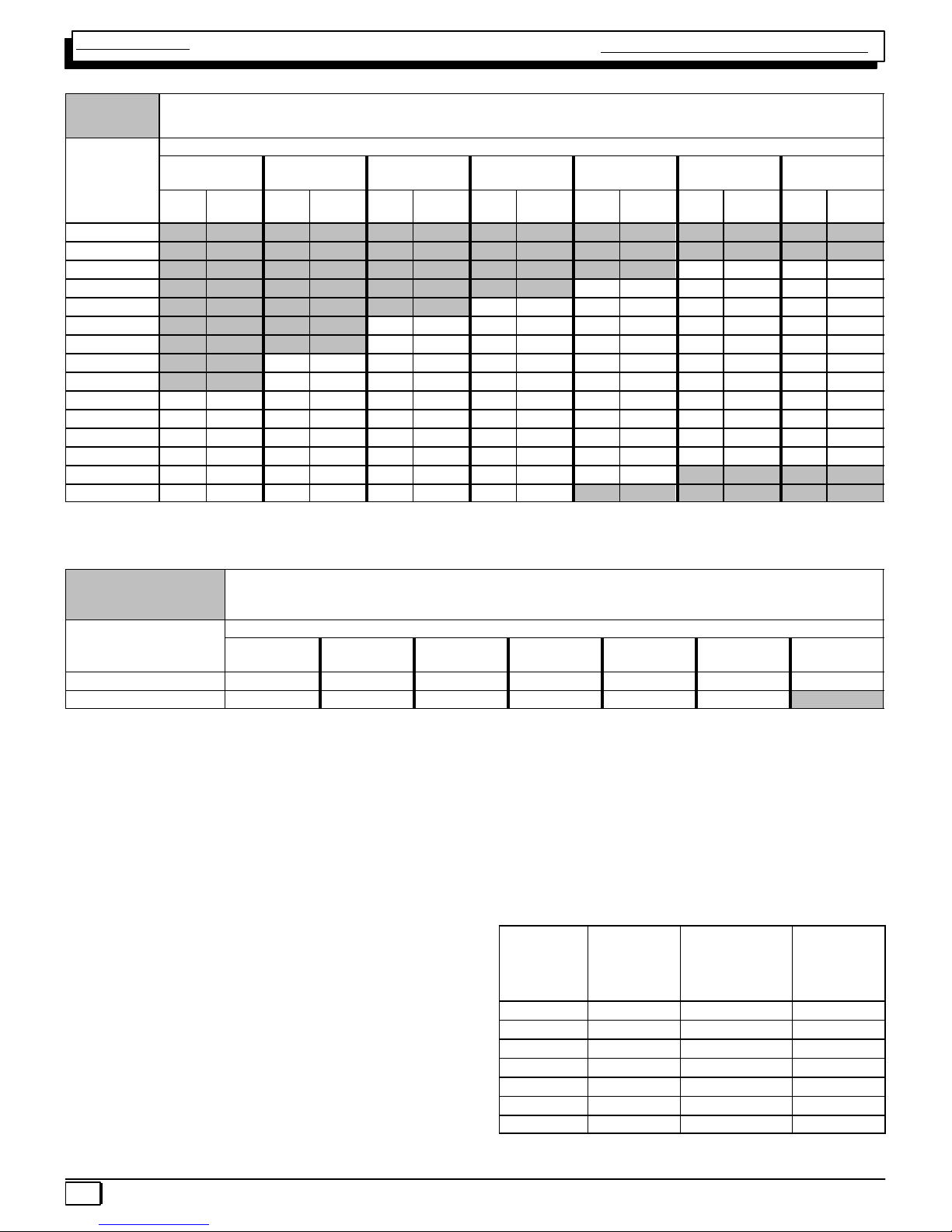
MANIFOLD PRESSURE AND ORIFICE SIZE FOR HIGH ALTITUDE APPLICATIONS
Table 2 NATURAL GAS MANIFOLD PRESSURE ( w.c.)
MEAN ELEVATION FEET ABOVE SEA LEVEL
HEATING
VALUE
at ALTITUDE
BTU/CU. FT.
0 to
2000
2001 to
3000
3001 to
4000
4001 to
5000
5001 to
6000
6001 to
7000
7001 to
8000
Orifice
No.
Manifold
Pressure
Orifice
No.
Manifold
Pressure
Orifice
No.
Manifold
Pressure
Orifice
No.
Manifold
Pressure
Orifice
No.
Manifold
Pressure
Orifice
No.
Manifold
Pressure
Orifice
No.
Manifold
Pressure
700 −− −− −− −− −− −− −− −− −− −− −− −− 41 3.7
725 −− −− −− −− −− −− −− −− −− −− 41 3.7 41 3.4
750 −− −− −− −− −− −− −− −− −− −− 41 3.5 42 3.6
775 −− −− −− −− −− −− −− −− 41 3.6 42 3.6 42 3.3
800 −− −− −− −− −− −− 41 3.6 42 3.7 42 3.4 42 3.1
825 −− −− −− −− 41 3.7 41 3.4 42 3.5 42 3.2 42 2.9
850 −− −− −− −− 41 3.5 42 3.6 42 3.3 42 3.0 42 2.8
875 −− −− 41 3.6 42 3.6 42 3.4 42 3.1 42 2.8 42 2.6
900 −− −− 42 3.7 42 3.4 42 3.2 42 2.9 42 2.7 42 2.5
925 41 3.7 42 3.5 42 3.3 42 3.0 42 2.8 42 2.5 44 3.3
950 41 3.5 42 3.3 42 3.1 42 2.9 42 2.6 42 2.4 44 3.1
975 42 3.7 42 3.2 42 2.9 42 2.7 42 2.5 44 3.2 45 3.6
1000 42 3.5 42 3.0 42 2.8 42 2.6 42 2.4 45 3.7 45 3.4
1050 42 3.2 42 2.7 42 2.5 44 3.3 45 3.6 −− −− −− −−
1100 43 3.6 42 2.5 44 3.2 45 3.6 −− −− −− −− −− −−
NOTE: Natural gas data is based on 0.60 specific gravity. For fuels with different specific gravity consult the National Fuel Gas Code ANSI
Z223.1−2002/NFPA 54−2002 or National Standard of Canada, Natural Gas And Propane Installation Code CSA B149.1−05.
Bold indicated the factory shipped orifice size #42.
Table 3 LPG or PROPANE GAS MANIFOLD PRESSURE ( w.c.)
FOR THE 90% 80,000 BTUH MODEL AND ALTERNATE INPUT RATINGS
HEATING VALUE
at ALTITUDE
BTU/CU. FT.
MEAN ELEVATION FEET ABOVE SEA LEVEL
0 to
2000
2001 to
3000
3001 to
4000
4001 to
5000
5001 to
6000
6001 to
7000
7001 to
8000
2500 10.0 10.0 10.0 10.0 9.4 8.5 10.0
Orifice Size #55 #55 #55 #55 #55 #55 #56
NOTE: Propane data is based on 1.53 specific gravity. For fuels with different specific gravity consult the National Fuel Gas Code ANSI Z223.1−2002/NFPA
54−2002 or National Standard Of Canada, Natural Gas And Propane Installation Code CSA B149.1−05.
NOTE: The derating of these furnaces at 2% (Natural Gas) and 4% (Propane Gas) has been tested and design−certified by
CSA. In Canada, the input rating must be derated 5% (Natural Gas) and 10% (Propane Gas) for altitudes of 2,000 to 4,500
above sea level. Use the 2001 to 3000 column in Table 2, Table 3, Table 4 and Table 5.
The burner orifice part nos. are as follows:
Orifice #41 1096942 Orifice #42 1011351
Orifice #43 1011377 Orifice #44 1011352
Orifice #45 1011353 Orifice #46 1011744
Orifice #47 1011378 Orifice #48 1113201
Orifice #49 1113202 Orifice #54 1011376
Orifice #55 1011354 Orifice #56 1011355
Single Stage Multi Position Furnace
Service Manual
440 08 2011 00
10
Table 4 NATURAL GAS MANIFOLD PRESSURE ( w.c.) FOR THE90% 80,000 BTUH MODEL AND
ALTERNATE INPUT MODELS
HEATING
VALUE
at ALTITUDE
BTU/CU. FT.
MEAN ELEVATION FEET ABOVE SEA LEVEL
0 to
2000
2001 to
3000
3001 to
4000
4001 to
5000
5001 to
6000
6001 to
7000
7001 to
8000
Orifice
No.
Manifold
Pressure
Orifice
No.
Manifold
Pressure
Orifice
No.
Manifold
Pressure
Orifice
No.
Manifold
Pressure
Orifice
No.
Manifold
Pressure
Orifice
No.
Manifold
Pressure
Orifice
No.
Manifold
Pressure
700 −− −− −− −− −− −− −− −− −− −− −− −− −− −−
725 −− −− −− −− −− −− −− −− −− −− −− −− −− −−
750 −− −− −− −− −− −− −− −− −− −− 41 3.6 41 3.6
775 −− −− −− −− −− −− −− −− 41 3.4 41 3.4 41 3.4
800 −− −− −− −− −− −− 42 3.5 42 3.5 42 3.5 42 3.5
825 −− −− −− −− 42 3.3 42 3.3 42 3.3 42 3.3 42 3.3
850 −− −− −− −− 42 3.1 42 3.1 42 3.1 42 3.1 42 3.1
875 −− −− 43 3.5 43 3.6 43 3.6 43 3.6 43 3.6 43 3.6
900 −− −− 43 3.3 43 3.4 43 3.4 43 3.4 43 3.4 43 3.4
925 44 3.7 44 3.7 44 3.7 44 3.7 44 3.7 44 3.7 44 3.7
950 44 3.5 44 3.5 44 3.5 44 3.5 44 3.5 44 3.5 44 3.5
975 44 3.3 44 3.3 44 3.3 44 3.3 44 3.3 44 3.3 44 3.3
1000 44 3.2 44 3.2 44 3.2 44 3.2 44 3.2 44 3.2 44 3.2
1050 46 3.6 46 3.6 46 3.6 46 3.6 46 3.6 −− −− −− −−
1100 46 3.3 46 3.3 46 3.3 46 3.3 −− −− −− −− −− −−
NOTE: Natural gas data is based on 0.60 specific gravity. For fuels with different specific gravity consult the National Fuel Gas Code ANSI
Z223.1−2002/NFPA 54−2002 or National Standard of Canada, Natural Gas And Propane Installation Code CSA B149.1−05.
Bold indicated the factory shipped orifice size #44.
Table 5 LPG or PROPANE GAS MANIFOLD PRESSURE ( w.c.)
FOR THE 80,000 BTUH MODEL AND ALTERNATE INPUT MODELS
HEATING VALUE
at ALTITUDE
BTU/CU. FT.
MEAN ELEVATION FEET ABOVE SEA LEVEL
0 to
2000
2001 to
3000
3001 to
4000
4001 to
5000
5001 to
6000
6001 to
7000
7001 to
8000
2500 10.0 10.0 9.0 10.0 9.4 8.5 10.0
Orifice Size #54 #54 #54 #55 #55 #55 #56
NOTE: Propane data is based on 1.53 specific gravity. For fuels with different specific gravity consult the National Fuel Gas Code ANSI
Z223.1−2002/NFPA 54−2002 or National Standard Of Canada, Natural Gas And Propane Installation Code CSA B149.1−05.
NOTE: The derating of these furnaces at 2% (Natural Gas) and 4% (Propane Gas) has been tested and design−certified by
CSA.
In Canada, the input rating must be derated 5% (Natural Gas) and 10% (Propane Gas) for altitudes of 2,000 to 4,500 above
sea level. Use the 2001 to 3000 column in Table 2, Table 3, Table 4 and Table 5.
General Derating Rules
1. These furnaces may be used at full input rating when
installed at altitudes up to 2,000′. When installed
above 2,000′, the input must be decreased 2% (natu-
ral) or 4% (LP) for each 1000′above sea level in the
USA. In Canada, the input rating must be derated 5%
(natural) or 10% (LP) for each 1000′above sea level.
See Table 4 or Table 5 for required high altitude in-
put rate.
2. For operation with natural gas at altitudes above
2,000′, orifice change and/or manifold pressure ad-
justments may be required for the gas supplied. First
consult your local gas supplier, then refer to Table 2
for required pressure change and/or orifice change
for high altitudes.
3. For operation with LP gas, gas orifices MUST be
changed and manifold pressure MUST be maintained
as per Table 3. Orifices can be ordered through your
distributor. (See Figure 6)
*High Altitude Input Rate =
Nameplate Sea Level Input Rate x (Multiplier)
Elevation
High Altitude
Multiplier
LP Gas*
Standard Input
High Altitude
Multiplier
LP Gas*
80,000 BTUH Input
Model
High Altitude
Multiplier
LP Gas*
Alternate Input
0′- 2000′1.00 1.00 0.80
2001′- 3000′0.90 1.00 0.80
3001′- 4000′0.86 1.00 0.80
4001′- 5000′0.82 1.00 0.80
5001′- 6000′0.78 0.96 0.76
6001′- 7000′0.74 0.92 0.72
7001′- 8000′0.70 0.88 0.68
* Based on mid−range of elevation.
Single Stage Multi Position Furnace Service Manual
440 08 2011 00 11
*High Altitude Input Rate =
Nameplate Sea Level Input Rate x (Multiplier)
Elevation
High Altitude
Multiplier
Natural Gas*
Standard Input
High Altitude
Multiplier
Natural Gas*
80,000 BTUH Input
Model
High Altitude
Multiplier
Natural Gas*
Alternate Input
0′- 2000′1.00 1.00 0.80
2001′- 3000′0.95 1.00 0.80
3001′- 4000′0.93 1.00 0.80
4001′- 5000′0.91 1.00 0.80
5001′- 6000′0.89 1.00 0.80
6001′- 7000′0.87 1.00 0.80
7001′- 8000′0.85 1.00 0.80
* Based on mid−range of elevation.
4. In cases where Table 2 or Table 3 is not applicable,
eg. alternate input rate application, refer to Table 4 or
Table 5 for required high altitude input rate.
Main Burner Flame Check
Allow the furnace to run approximately 10 minutes. Then inspect
the main burner flames. See Figure 5.
Check for the following:
•Stable and blue flames. Dust may cause orange tips
or wisps of yellow, but flames MUST NOT have solid,
yellow tips.
•Flames extending directly from burner into heat ex-
changer.
•Flames do NOT touch sides of heat exchanger
If any problems with main burner flames are noted, it may
be necessary to adjust gas pressures or check for drafts.
Main Burner
Burner Face
10−10−78
Figure 5
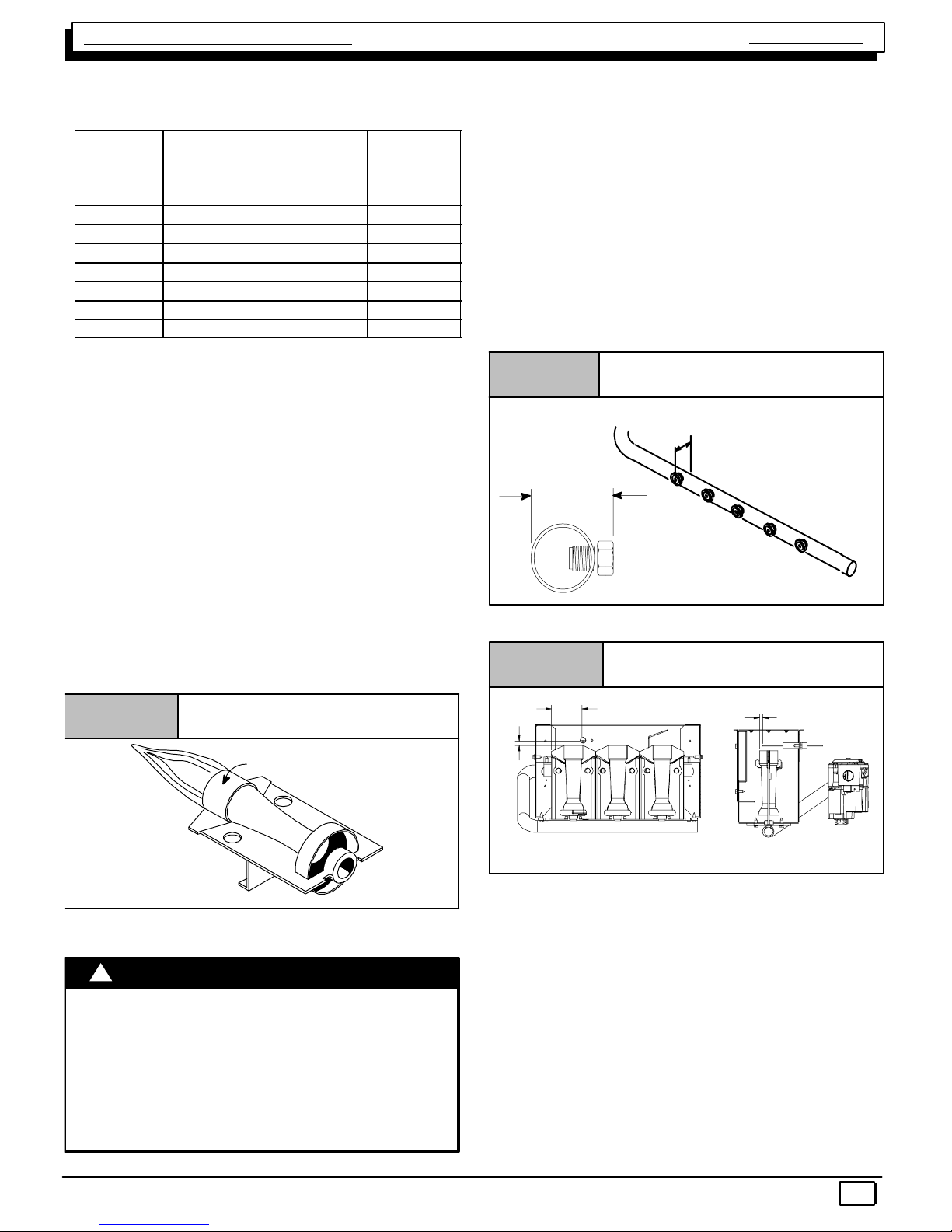
Changing Orifices for High Altitude
ELECTRICAL SHOCK, FIRE OR EXPLOSION
HAZARD
Failure to properly install orifices could result in
death, personal injury and/or property damage.
Turn OFF electric power (at disconnect) and gas
supply (at manual valve in gas line) when installing
orifices. Installation of orifices requires a qualified
service technician.
!WARNING
NOTE: Main burner orifices can be changed for high alti-
tudes.
1. Disconnect gas line from gas valve.
2. Remove manifold from furnace.
3. Remove the orifices from the manifold and replace
them with properly sized orifices.
4. Tighten the orifices so they are seated and gas tight
approximately 11/8″from the face of the orifice to the
back of the manifold pipe. (See Figure 6) Make sure
orifice is installed straight so that it forms a right angle
(90°) to the manifold.
5. Reinstall manifold. Ensure burners do NOT bind on
new orifices.
Figure 6 Changing Orifices
11/8″to 13/16″
Measure from face of orifice
to the back side of the
manifold.
NOTE: For Ignitor location see Figure 7.
Ignitor Location
Figure 7
5/16 1/4
21/16
NOTE: Flame sensor has a different orientation for all
050 models and alternate 040 input.
all dimensions are in inches.
High Altitude Installation
Gas input rate on the furnace rating plate is for installation at up to
2000′. The #54 burner orifices supplied in this kit are sized for Pro-
pane Gas at full rate ONLY, for use between 0−2000′elevation. Do
not use them above 2000′(except when noted by Table 3 or
Table 5). Orifices for conversion at high altitude and alternate input
must be ordered from Service Parts.
Standard Input:
Units may be installed at full input rating (25,000 BTUH per heat
exchanger) when installed at altitudes up to 2000′.
80,000 BTUH model and Alternate Input (Conversions): See unit
instructions to determine if model may be converted to alternate in-
put.
Units may be installed at full input rating (20,000 BTUH per heat
exchanger) when installed at altitudes up to 5000′.
Single Stage Multi Position Furnace
Service Manual
440 08 2011 00
12
In the USA, for furnaces fired on standard rate, the input rating for
altitudes above 2000′(5,000for 80,000 BTUH and alternate in-
put) must be derated by 4% for each 1000′above sea level (see
Table 3 and Table 5)
In Canada, the input rating for altitudes above 2000′(5,000for
80,000 BTUH) must be reduced by 10% for altitudes of 2000′to
4500′above sea level. Use the 2001 to 3000 column in Table 3
and Table 5.
Alternate BTUH Input Ratings (USA Only)
The input rating of these furnaces can be changed from the stan-
dard input rating to the alternate input rating shown in Table 6, by
changing the main burner orifices. Changing of burner orifices
MUST be done by a qualified service technician. See section on
changing orifices.
CAUTION: See unit instructions to determine if model may be
converted to alternate input.
Table 6 Alternate Input Ratings, USA ONLY.
BTUH
Standard
Rating
BTUH
Alternate
Rating
LP
Gas
Orifice*
50,000 40,000 #55
75,000 60,000 #55
100,000 80,000 #55
125,000 100,000 #55
* See Table 5 for High Altitude
MANIFOLD PRESSURE AND ORIFICE SIZE FOR HIGH ALTITUDE APPLICATIONS
Table 7 LPG or PROPANE GAS MANIFOLD PRESSURE ( w.c.)
EXCEPT FOR THE 90% 80,000 BTUH MODEL AND ALTERNATE INPUT RATINGS
HEATING VALUE
at ALTITUDE
BTU/CU. FT.
MEAN ELEVATION FEET ABOVE SEA LEVEL
0 to
2000
2001 to
3000
3001 to
4000
4001 to
5000
5001 to
6000
6001 to
7000
7001 to
8000
2500 10.0 10.0 9.0 10.0 9.4 8.5 10.0
Orifice Size #54 #54 #54 #55 #55 #55 #56
Table 8 LPG or PROPANE GAS MANIFOLD PRESSURE ( w.c.)
FOR THE 90% 80,000 BTUH MODEL AND ALTERNATE INPUT RATINGS
HEATING VALUE
at ALTITUDE
BTU/CU. FT.
MEAN ELEVATION FEET ABOVE SEA LEVEL
0 to
2000
2001 to
3000
3001 to
4000
4001 to
5000
5001 to
6000
6001 to
7000
7001 to
8000
2500 10.0 10.0 10.0 10.0 9.4 8.5 10.0
Orifice Size #55 #55 #55 #55 #55 #55 #56
NOTE: Propane data is based on 1.53 specific gravity. For fuels with different specific gravity consult the National Fuel Gas Code ANSI Z223.1−2002/NFPA
54−2002 or National Standard Of Canada, Natural Gas And Propane Installation Code CSA B149.1−05.
NOTE: In the USA, for furnaces fired on standard rate, the input rating for altitudes above 2000′(5,000for 80,000 BTUH and alternate
input) must be derated by 4% for each 1000′above sea level (see Table 3 and Table 5)
In Canada, the input rating for altitudes above 2000′(5,000for 80,000 BTUH) must be reduced by 10% for altitudes of 2000′to 4500′
above sea level. Use the 2001 to 3000 column in Table 3 and Table 5.
L.P. PRESSURE SWITCH
Models equipped for or converted to operate on LP Gas will
be equipped with an LP Pressure Switch. If so equipped,
the switch will be located in the gas supply line (in a “Tee”
fitting), just ahead of the gas valve.
The purpose of this switch is to prevent furnace operating
under low line (Supply) pressure conditions. Operating un-
der low line pressure conditions, can create problems such
as incomplete combustion, flashback, sooting, etc.
The switch is a “Normally Open” pressure operated switch
that is wired in series with the furnace (air proving) pressure
switch. The L.P. Pressure Switch closes when line (Supply)
pressure is 8.0″W.C. or higher. the L.P. Pressure Switch
Opens if line pressure falls below 6.0″+0.6″W.C. inter-
rupting power to the gas valve.
Typical L.P. Pressure Switch
Figure 8
Single Stage Multi Position Furnace Service Manual
440 08 2011 00 13
HONEYWELL VR8205S Gas Valve
The VR8205S Gas Valve is a REDUNDANT type valve.
This means that it consists of two (2) valves (internally) with
independent operators (solenoids) that both must be ener-
gized before gas can flow through the valve. This redundan-
cy provides an added safety measure. In case one of the
valves sticks open (Mechanically), the second operator will
close preventing the flow of gas.
If the valve does not open, check for 24 Volts across the two
wires to the valve during a call for heat. This check MUST
be made IMMEDIATELY following the igniter warm−up peri-
od (17 seconds). 24 Volts will be present ONLY for a period
of 7 seconds after the igniter warm−up if flame is not proven.
If 24 Volts is present during the above check and the valve
will NOT open, then replace the valve. If 24 Volts IS NOT
present, problems are indicated in the control and/or wiring
to the gas valve.
HIGH ALTITUDE OPERATION
These furnaces are designed to operate in the majority of
the country without modifications. At altitudes over 2,000′
above sea level, however, certain measures need to be tak-
en to insure continued, safe reliable operation. For exam-
ple, units must be de−rated for altitude (by adjusting man-
ifold pressure and/or changing orifice size) based upon the
type of fuel (I.E. Natural Gas or L.P. gas), Btu content of the
gas, and installed altitude.
Altitudes over 4,000′may require a different air proving
pressure switch than the one installed at the factory. Check
parts list for pressure switch and consult your distributor for
part number and availability. In Canada, provincial codes
may govern installation or switch. Check with governing au-
thorities.
When servicing a unit installed at altitudes above 2,000′in-
sure that it has been properly modified to operate at that alti-
tude. See the sections on Gas pressure (Page 10), and
pressure switches (Page 15) to obtain specific information
for you particular installation altitude.
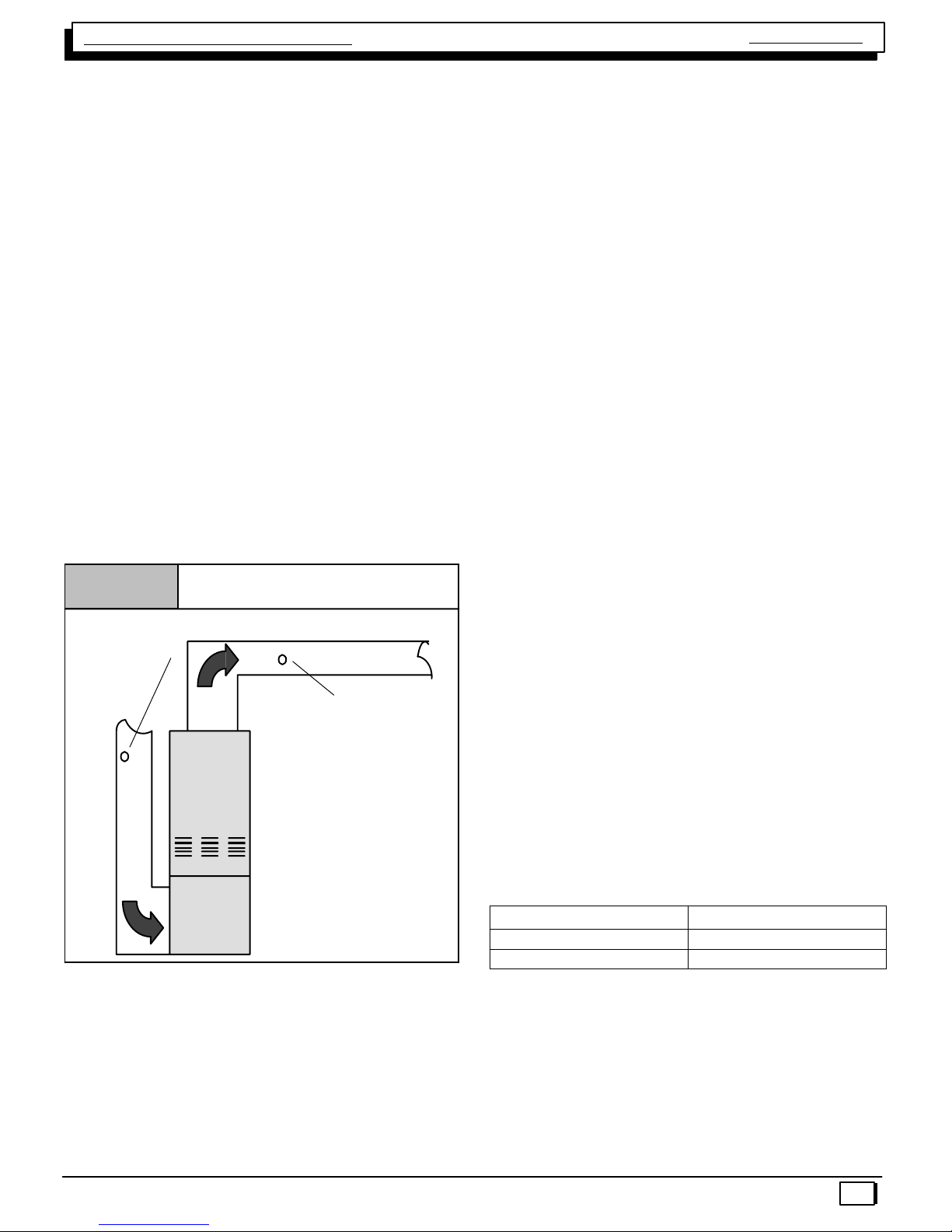
CHECKING TEMPERATURE RISE
Air Flow
Checking Temperature Rise
Figure 9
Thermometer:
Return Air Temp.
Thermometer;
Supply Air Temp.
Supply
Air Flow
Return
Temperature Rise Check
The blower speed MUST be set to give the correct air tem-
perature rise through the furnace as marked on the rating
plate. Temperature rise is the difference between supply
and return air temperatures.
To check temperature rise,use the following procedure:
1. Place thermometers in supply and return air registers
as close to furnace as possible, avoiding direct ra-
diant heat from heat exchangers.
2. Operate furnace continuously for 15 minutes with all
registers and duct dampers open.
3. Take reading and compare with range specified on
rating plate.
4. If the correct amount of temperature rise is NOT ob-
tained, it may be necessary to change blower speed.
A higher blower speed will lower the temperature rise.
A lower blower speed will increase the temperature
rise.
NOTE: BEFORE CHECKING TEMPERATURE RISE BE
CERTAIN THAT MANIFOLD PRESSURE IS PROPERLY
ADJUSTED.
ALLOWABLE TEMPERATURE RISE ALL MODELS
Model Range
50, 80 Mbtu 35°F −65°F
75, 100 & 125 Mbtu 40°F −70°F
Example:
Supply Temp. 170°
Return Temp. 70°
Temperature Rise 100°= Too High
Solution: Increase Blower Speed

Single Stage Multi Position Furnace
Service Manual
440 08 2011 00
14
ROOM THERMOSTATS
Room thermostats are available from several different
manufactures in a wide variety of styles. They range from
the very simple and inexpensive Bi−metallic type to the
complex and costly electronic set−back type. They are sim-
ply a switch (or series of switches) designed to turn equip-
ment (or components) “ON” or “OFF” at the desired condi-
tions.
An improperly operating, or poorly located room thermostat
can be the source of perceived equipment problems. A
careful check of the thermostat and wiring must be made
then to insure that it is not the source of problems.
Thermostat Location
Figure 10
5 ft.
DRAFTS
SUN
THERMOSTAT
LIGHT
SHIELD
LOCATION
The thermostat should not be mounted where it may be af-
fected by drafts, discharge air from registers (hot or cold),
or heat radiated from the sun or appliances. Never install in
alcoves, bathrooms or bedrooms.
The thermostat should be located about 5 ft. above the floor
in an area of average temperature, with good air circulation.
Normally, an area in close proximity to the return air grille
is the best choice.
Mercury bulb type thermostats MUST be level to control
temperature accurately to the desired set−point. Electronic
digital type thermostats SHOULD be level for aesthetics.
HEAT ANTICIPATORS
Heat anticipators are small resistance heaters built into
most electric−mechanical thermostats. Their purpose is to
prevent wide swings in room temperature during furnace
operation.
In order to accomplish this, the heat output from the antici-
pator must be the same regardless of the current flowing
through it. Consequently, most thermostats have an adjust-
ment to compensate for varying current draw in the thermo-
stat circuit.
The proper setting of heat anticipators then is important to
insure proper temperature control and customer satisfac-
tion.
Measuring Current Draw
Figure 11
Ammeter
W
R
Subbase
Amps
The best method to obtain the required setting for the heat
anticipator, is to measure the actual current draw in the con-
trol circuit (“W”) using a low range (0−2.0 Amps) Ammeter.
(See Figure 11) After measuring the current draw, simply
set the heat anticipator to match that value.
If a low range ammeter is not available, a “Clamp−on” type
meter may be used as follows:
1. Wrap EXACTLY ten (10) turns of wire around the jaws
of a clamp−on type ammeter.
2. Connect one end of the wire to the “W” terminal of the
thermostat sub−base, and the other to the “R” termi-
nal.
3. Turn power on, and wait approximately 1 minute, then
read meter.
4. Divide meter reading by 10 to obtain correct anticipa-
tor setting.
Electronic thermostats do not use a resistance type antici-
pator. These thermostats use a microprocessor (computer)
that determines a cycle rate based on a program loaded into
it at the factory.
These cycle rates are normally field adjustable for different
types to equipment. The method of adjustment, however,
varies from one thermostat manufacturer to another. Check
with the thermostat manufacturer to find out the proper way
of adjusting the cycle rate.
CONTROL WIRING
Control wiring is an important part of the total equipment
installation, since it provides the vital communications link
between the thermostat, and the equipment. Control wiring
that is either too long, undersized, or improperly connected
(be it simply loose, or on the wrong terminal) can in fact be
the source of many equipment problems.
Single Stage Multi Position Furnace Service Manual
440 08 2011 00 15
ALWAYS check to make sure that the control wiring is con-
nected to the proper terminal(s) of the equipment and ther-
mostat you are using. Remember, also, that the thermostat
terminals are not always identified alike by different thermo-
stat manufacturers. Connections MUST be clean and tight
to insure trouble−free operation.
ELECTRONIC CONTROLS used on this series of furnace
RESPOND DIFFERENTLY to certain control wiring practic-
es which have been generally accepted in the HVAC indus-
try for many years.
For Example: For years, installers have run a wire from the
“Y” terminal of the room thermostat and connected it direct-
ly to the contact on coil of a condensing unit. (not making
any connection to the furnace with this wiring. Then, run the
low voltage “Common” wire from the condensing unit back
to the “C” terminal of the furnace.
With the electronic Furnace Control Board used in this se-
ries, however the “Y” terminal of the furnace does in fact
serve a particular purpose. Failure to connect it will result
in certain improper operation as follows:
The COOLING fan speed is energized via the “Y” terminal.
Failure to connect the thermostat “Y” terminal to the “Y”
terminal on the control will result in the failure to energize
the COOLING speed on a call for cooling from the thermo-
stat. (The HEATING speed will be energized instead via the
“G” terminal)
TWINNING KITS
Some installations may require a Heating capacity or Air-
flow capabilities greater than a single furnace of this series
can provide. When this is necessary, furnaces may be
installed in a “Twinned” configuration.
The Twinning Kit allows the two (2) identical furnaces to be
controlled by the same room thermostat. When Twinned,
the circulating (conditioned air) blowers of BOTH furnaces
will operate simultaneously. The kit part no. for the “C” se-
ries or later furnace is NAHA004WK.
LIMIT SWITCHES
Two (2) different kinds of limit switches are used on this se-
ries of furnaces. They are the main limit and roll out limit
switch. The main limit, and roll limit switches are used on
ALL models.
NOTE: All limit switches are safety devices and other
than for testing purposes, should never be jumped out!
Limit switches are “normally closed” electrical switches, de-
signed to open when their predetermined “limit setting” has
been reached.
It should also be remembered, that when a limit switch
opens, it more than likely is not due to a bad switch! The
cause of the opening limit must be found and corrected, be-
fore the furnace can resume proper operation.
FIRE HAZARD.
Failure to do so can result in death, personal injury
and/or property damage.
Limit controls are factory preset and MUST NOT be
adjusted. Use ONLY manufacturer’s authorized
replacement parts.
!
The specific functions of the two (2) limit switches
used in this series of furnaces are as follows:
MAIN LIMIT SWITCH
There is a “Normally Closed” switch located on the front
partition of the furnace. It monitors supply air temperature,
and interrupts furnace (burner) operation when a supply air
temperature is sensed which would result in the furnace ex-
ceeding Maximum allowable outlet air temperature. While
the main limit is open, the combustion blower, and the circu-
lating blower will be energized continuously. This control is
an “Automatic” reset control, which will reset itself when the
temperature sensed drops to a safe level.
If furnace (burner) cycles on this limit switch, (I.E. switch
opens and closes during furnace operation) it is more than
likely due to a high temperature rise through the furnace.
(See checking temperature on page 10 of this manual)
High temperature rise can be caused by either OVER
FIRING (high manifold pressure. incorrect orifices, etc.) or
LOW AIR FLOW (dirty filter, blower speed too low, exces-
sive static in duct system, etc.)
Single Stage Multi Position Furnace
Service Manual
440 08 2011 00
16
N9MP1 & N9MP2 MAIN LIMIT SWITCH
MODEL PART # OPEN CLOSE
050B12C 34335002 240°F 220°F
075B12C 34335001 210°F 190°F
080F16C 1320361 230°F 210°F
100F14C 1320361 230°F 210°F
100J20C 1320367 220°F 200°F
125J20C 1008445 190°F 170°F
ROLL OUT LIMIT SWITCH
MODEL PART # OPEN CLOSE
ALL 1013102 300°F MANUAL
*9MPD MAIN LIMIT SWITCH
MODEL PART # OPEN CLOSE
050B12C 1320366 260°F 240°F
075F12C 34335002 240°F 220°F
080J16C 1320367 220°F 200°F
100J14C 1320367 220°F 200°F
100J20C 1320367 220°F 200°F
125L20C 1008445 190°F 170°F
ROLL OUT LIMIT SWITCH
MODEL PART # OPEN CLOSE
ALL 1013102 300°F MANUAL
To verify this, the cut−out (opening) point of the switch
should be checked (using a thermocouple type thermome-
ter connected to the face of the switch) as follows:
1. Operate furnace for several minutes.
2. Block return air grille(s) to furnace.
3. Observe temperature at which switch opens (burner
operation ceases).
4. Remove blockage from return grille(s).
5. Observe temperature at which switch closes (burner
operation resumes).
6. Compare readings with the limit setting listed in the
appropriate chart for the model you are servicing.
If switch is opening within the specified range, then it is sim-
ply doing its job, and the cause of the over−temperature
must be determined and corrected.
If, however, the switch is found to be opening prematurely,
then it should be replaced. When replacing ANY limit
switch, use ONLY a switch of EXACTLY the same tempera-
ture setting. Use of a different temperature limit switch can
create a dangerous situation. Some of the main limit
switches used in this series are SIMILAR IN AP-
PEARANCE. DIFFERENT TEMPERATURE SETTINGS,
HOWEVER, ARE USED for different models. Be certain
you have the correct control for the model you are servicing.
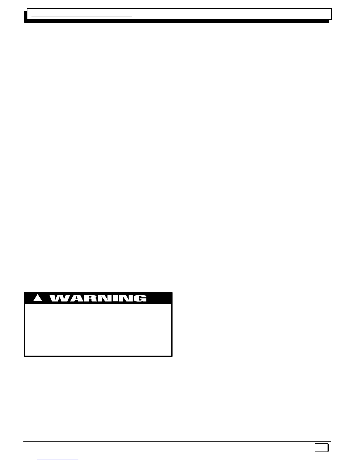
ROLL OUT LIMIT
A “Normally Closed” switch (wired in series with the Main
Limit switch) mounted on both sides of the burner box.
This switch is a manual reset type. When replacing this
switch, be absolutely certain the correct one is used.
Typical Roll Out Limit Switch
Figure 12
NEVER use an automatic reset roll out switch to
replace a manual reset type roll out switch.
Doing so may cause potentially unsafe and/or
intermittent operation.
!CAUTION
The roll out switch monitors the temperature inside the
burner box, and interrupts furnace (burner) operation when
its temperature indicates flame roll out has occurred.
Once the roll out switch has opened, burner operation will
be prevented until the roll out switch is “Manually Reset” by
pressing the red button located on the switch. While the roll
out switch is open, the combustion blower and circulating
blower will be energized continuously.
If the roll out switch has opened, the cause must be deter-
mined. Some possible reasons for flame roll out include a
restricted primary or secondary heat exchanger or over
fired furnace.
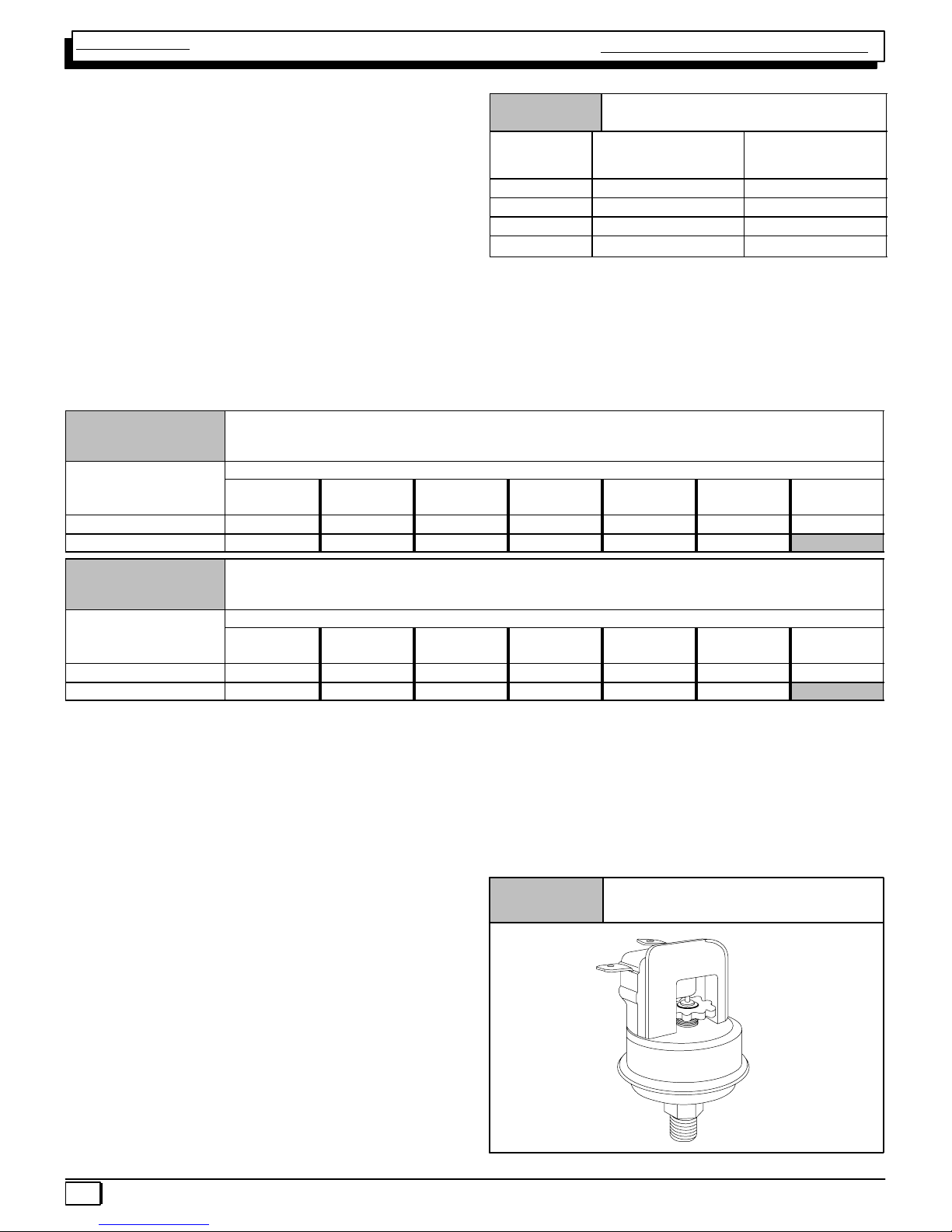
PRESSURE SWITCHES
Transition Pressure Switch
An air proving switch (pressure) switch is used on all mod-
els to insure that a draft has been established through the
heat exchanger before allowing burner operation.
All models use a single tap (port) type switch. This switch
senses the negative pressure created by (at) the combus-
tion blower.
Under normal operating conditions, sufficient pressure is
developed by the exhaust (combustion) blower to close the
Single Stage Multi Position Furnace Service Manual
440 08 2011 00 17
switch, and permit the burner to operate. As the condensate
drain begins to back−up, however, the pressure begins to
reduce. When the pressure drops sufficiently, burner opera-
tion will be prevented until the condition is corrected.
N9MP1 STANDARD TRANSITION SWITCH
MODEL PART # OPEN ″W.C. CLOSE″W.C
050B12C 1013802 −2−2.2
075B12C 1013802 −2−2.2
080F16C 1013811 −1.6 −1.8
100F14C 1013801 −2.1 −2.3
100J20C 1013802 −2−2.2
125J20C 1013166 −1.6 −1.8
N9MP1 STANDARD INDUCER SWITCH
MODEL PART # OPEN ″W.C. CLOSE ″W.C.
125J20C 1013166 −1.1 −1.3
N9MP1 HIGH ALTITUDE TRANSITION SWITCH
MODEL PART # OPEN ″W.C. CLOSE ″W.C.
050B12C 1013803 −1.8 −2
075F12C 1013803 −1.8 −2
080F16C 1013812 −1.3 −1.5
100F14C 1013803 −1.8 −2
100J20C 1013803 −1.8 −2
125L20C 1013157 −1.5 −1.7
N9MP1 HIGH ALTITUDE INDUCER SWITCH
MODEL PART # OPEN ″W.C. CLOSE ″W.C.
125J20C 1013157 −0.7 −0.9
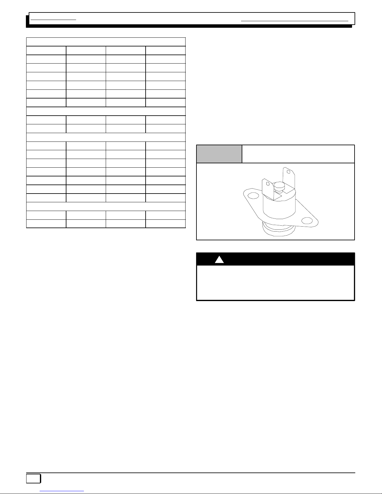
Pressure Switch
Figure 13
Pressure Port
Normally Open
Terminal
Common
Terminal
N9MP2 STANDARD TRANSITION SWITCH
MODEL PART # OPEN ″W.C. CLOSE″W.C
050B12C 1013802 −2−2.2
075B12C 1013801 −2.1 −2.3
080F16C 1013811 −1.6 −1.8
100F14C 1013801 −2.1 −2.3
100J20C 1013802 −2−2.2
125J20C 1013166 −1.6 −1.8
N9MP2 STANDARD INDUCER SWITCH
MODEL PART # OPEN ″W.C. CLOSE ″W.C.
125J20C 1013166 −1.1 −1.3
N9MP2 HIGH ALTITUDE TRANSITION SWITCH
MODEL PART # OPEN ″W.C. CLOSE ″W.C.
050B12C 1013803 −1.8 −2
075F12C 1013803 −1.8 −2
080F16C 1013812 −1.3 −1.5
100F14C 1013803 −1.8 −2
100J20C 1013803 −1.8 −2
125L20C 1013157 −1.5 −1.7
N9MP2 HIGH ALTITUDE INDUCER SWITCH
MODEL PART # OPEN ″W.C. CLOSE ″W.C.
125J20C 1013157 −0.7 −0.9
*9MPD STANDARD TRANSITION SWITCH
MODEL PART # OPEN ″W.C. CLOSE″W.C
050B12C 1013802 −2−2.2
075B12C 1013802 −2−2.2
080F16C 1013812 −1.3 −1.5
100F14C 1013802 −2−2.2
100J20C 1013802 −2−2.2
125J20C 1013166 −1.6 −1.8
*9MPD STANDARD INDUCER SWITCH
MODEL PART # OPEN ″W.C. CLOSE ″W.C.
125J20C 1013166 −1.1 −1.3
*9MPD HIGH ALTITUDE TRANSITION SWITCH
MODEL PART # OPEN ″W.C. CLOSE ″W.C.
050B12C 1013803 −1.8 −2
075B12C 1013803 −1.8 −2
080F16C 1013813 −1−1.2
100F14C 1013803 −1.8 −2
100J20C 1013803 −1.8 −2
125L20C 1013157 −1.5 −1.7
*9MPD HIGH ALTITUDE INDUCER SWITCH
MODEL PART # OPEN ″W.C. CLOSE ″W.C.
125J20C 1013157 −0.7 −0.9
To insure continued SAFE, RELIABLE, operation NEVER
SUBSTITUTE a pressure switch with one that is similar in
Single Stage Multi Position Furnace
Service Manual
440 08 2011 00
18
appearance. ONLY FACTORY PROVIDED or AU-
THORIZED SUBSTITUTES ARE ACCEPTABLE.
Furnaces installed at altitudes of 4,000′above sea level or
higher may require replacing the standard pressure switch
with a high altitude pressure switch. The different pressure
switch settings allow continued SAFE RELIABLE high alti-
tude operation.
Under normal operating conditions, sufficient negative
pressure will be created to close the pressure switch, and
keep it closed to keep furnace operating. Under abnormal
conditions, however, such as a restricted vent pipe, or a
leak in one of the heat exchangers, sufficient negative pres-
sure will not be created. This will result in the switch failing
to close or failing to remain closed during furnace operation.
When servicing a unit whose pressure switch will not close,
or remain closed during operation, the operating pressure
of that furnace should be checked and compared to
approximate operating pressures listed in this manual and
the switch setting(s) listed above for the model family you
are servicing.
It is important to remember, that greater negative pressures
are created by the furnace when “HOT” (I.E. upon initial
start−up) than when “COLD” (I.E. after furnaces has been
in operation for a few minutes). Because of this, furnace
pressure should ONLY be checked when “HOT” to insure
accurate readings.
The tables list approximate operating pressures. They are
included in this manual to provide you with a “Barometer”
to gauge your pressures against. The pressures you obtain
in the field will differ slightly from these figures based upon
vent length, gas pressure, operating temperature, etc.
Major discrepancies in pressures, will normally cause
problems with pressure switch operation. These Major dis-
crepancies should be investigated as follows:
Lower (Lesser) Negative Pressures
Lower than normal negative pressures measured at the
Combustion Blower may be caused by:
1. Restriction on the Outlet side of the combustion blow-
er. (I.E. Blocked Flue, Vent too long, Heat Exchanger
leak, etc.)
2. Leak (lack of restriction) on the Inlet side of the com-
bustion blower.
Higher (Greater) Negative Pressures
Higher than normal negative pressures measured at the
Combustion Blower may be caused by:
1. Restriction on the Inlet side of the combustion blower.
(I.E. Plugged Heat Exchanger, air inlet orifice too
small)
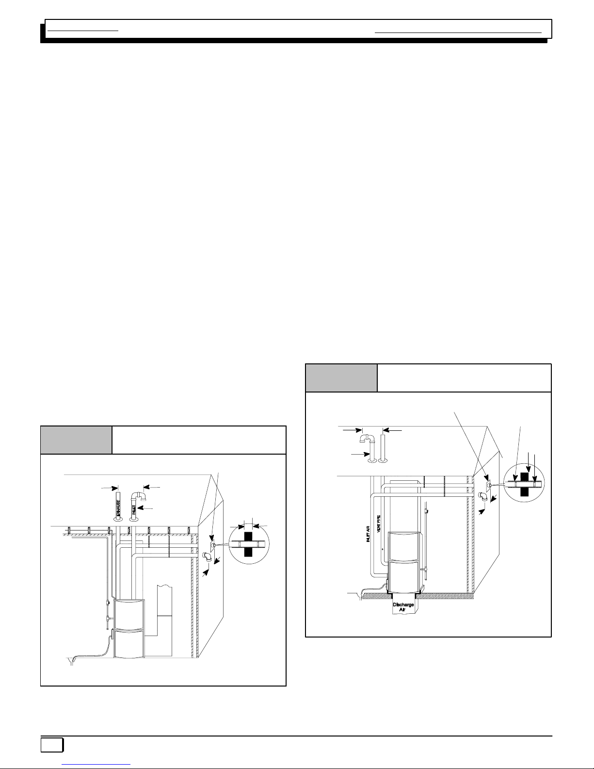
Vent Pipes MUST be
supported Horizontally
and Vertically
*8″Min.
20′Max.
in same atmospheric
zone
*8″Min.
20′Max.
in same
atmospheric
zone
Coupling on ends of
exhaust pipe. Total
pipe & coupling out-
side structure = 8″
Figure 14 Typical Upflow Installation
Aluminum or non−rusting shield recommended. (See
Vent Termination Shielding for dimensions).
*Increase minimum from 8″to 18″for cold climates (sustained temperatures below
0 °F).
DISCHARGE AIR
25−23−33
Inlet Pipe (not
used on Single
Pipe model)
*8″Min.
20′Max.
in same
atmospheric zone
Figure 15 Typical Downflow Installation
Vent Pipes MUST be
supported Horizontally
and Vertically
* Increase minimum from 8″to 18″for cold climates (sustained temperatures
below 0°F).
See Vent Termination
Shielding in Vent Sec-
tion.
*8″Min.
20′Max.
in same
atmospheric zone
8″Min.
Coupling on inside
and outside of wall
to restrain vent pipe
25−23−33a
Inlet Pipe
(not used on
Single Pipe
model)

Single Stage Multi Position Furnace Service Manual
440 08 2011 00 19
VENT/COMBUSTION AIR PIPING
Vent and combustion air piping are an extremely important
part of the total furnace installation. Improperly installed or
inadequately sized vent and/or combustion air piping can
be the source of many perceived furnace problems.
For example, most problems associated with pressure
switch operation can normally be traced to short comings
in the vent and/or combustion air piping. Anytime these type
problems arise, a thorough inspection of the vent and/or
combustion air piping should be conducted.
ALL MODELS require a vent (exhaust) pipe to carry flue
products to the outside of the structure.
Direct VENT (ONLY) models require a combustion air inlet
to bring in all air for combustion from outside the struc-
ture.
DUAL CERTIFIED models require a combustion air inlet
pipe to bring in all air for combustion from outside the struc-
ture only when installed as a Direct Vent Furnace (I.E. Two
Pipe Installation)
Consult the appropriate Venting tables and/or piping chart
for the model you are servicing.
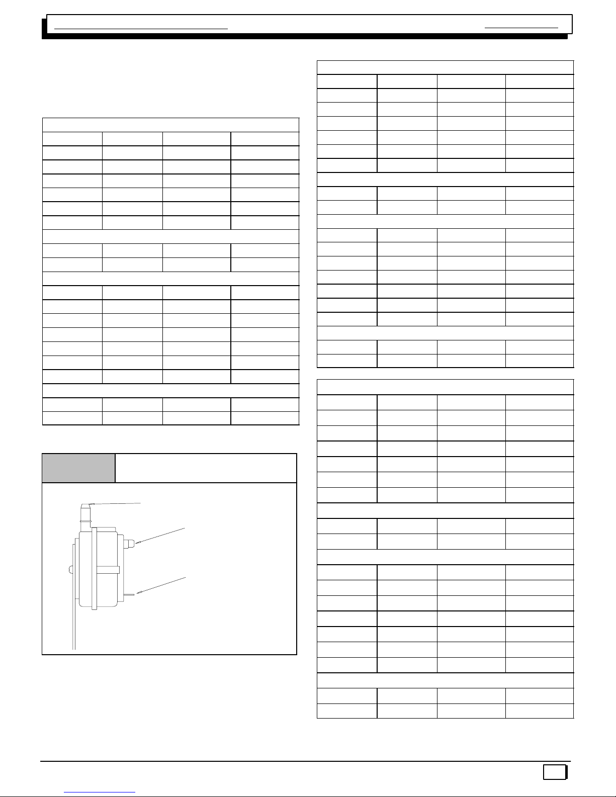
STANDARD VENT TERMINATION
Vent/Combustion Air Piping Charts
Sizing Combustion Air and Vent Pipe
Consult Table 9 or Table 10 to select the proper diameter
exhaust and combustion air piping. Exhaust and combus-
tion air piping is sized for each furnace Btuh size based on
total lineal vent length (on inlet or outlet side), and number
of 90°elbows required. Two 45°elbows can be substituted
for one 90°elbow. The elbow or elbows used for vent ter-
mination outside the structure ARE counted, including el-
bows needed to bring termination above expected snow
levels. The elbow inside the furnace on the *9MPD IS NOT
included in the count.
Table 9 Pipe Diameter Table
N9MP1 & *9MPD Models
50,000, 75,000 & 80,000 Btuh Furnaces
40′& (5) 90°elbows with 2″PVC pipe or
70′& (5) 90°elbows with 3″PVC pipe
100,000 Btuh Furnace
40′& (5) 90°elbows with 3″PVC pipe or
70′& (5) 90°elbows with 3″PVC pipe &
Long Vent Kit (See Tech. Manual)
125,000 Btuh Furnace
40′& (5) 90°elbows with 3″PVC pipe
Elbows are DWV Long Radius Type for 2″and 3″vents.
If more than five elbows are required, reduce the length of
both the inlet and exhaust pipes 5′for each additional elbow
used.
NOTE: It is allowable to use larger diameter pipe and fitting than
shown in the tables but not smaller diameters than shown.
Table 10 Pipe Diameter Table
N9MP2 Models
50,000 & 80,000 Btuh Furnaces
40′& (5) 90°elbows with 2″PVC pipe or
70′& (5) 90°elbows with 3″PVC pipe
75,000 Btuh Furnaces
25′& (3) 90°elbows with 2″PVC pipe or
40′& (5) 90°elbows with 2″PVC pipe &
Long Vent Kit (See Tech. Manual) or
70′& (5) 90°elbows with 3″PVC pipe
100,000 Btuh Furnace
40′& (5) 90°elbows with 3″PVC pipe or
70′& (5) 90°elbows with 3″PVC pipe &
Long Vent Kit (See Tech. Manual)
125,000 Btuh Furnace
40′& (5) 90°elbows with 3″PVC pipe
Elbows are DWV Long Radius Type for 2″and 3″vents.
If more than five elbows are required, reduce the length of
both the inlet and exhaust pipes 5′for each additional elbow
used.
NOTE: It is allowable to use larger diameter pipe and fitting than
shown in the tables but not smaller diameters than shown.
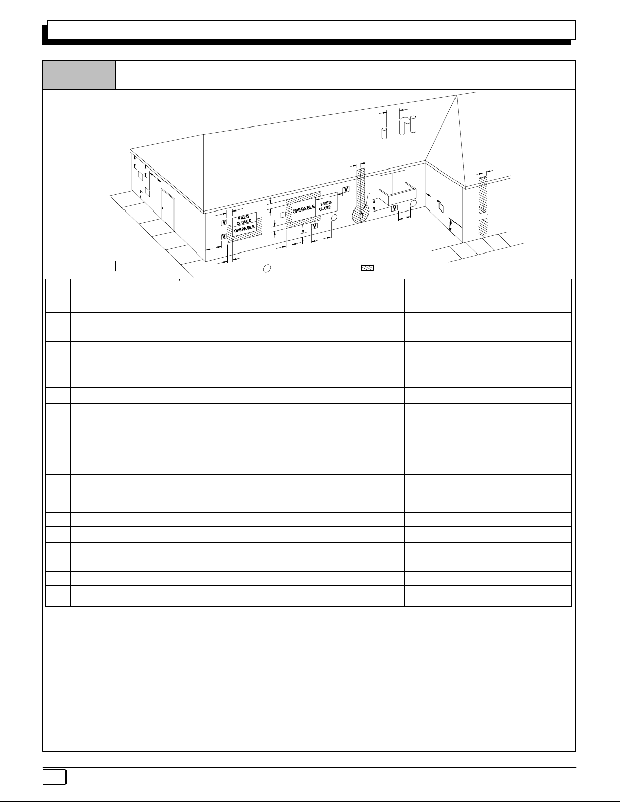
A
X
B
V
V
V
V
X
X
AIR SUPPLY INLET
VVENT TERMINAL AREA WHERE TERMINAL IS NOT PERMITED
A
B
B
B
B
B
C
D
E
F
J
I
L
H
K
G
25−24−65−2
N
Y
Y
X
M
V
O
Direct Vent Termination Clearance
Figure 16
Single Stage Multi Position Furnace
Service Manual
440 08 2011 00
20
Item Clearance Description Canadian Installation (1) U.S. Installation (2)
AClearance above grade, veranda, porch, deck, balcony, or
anticipated snow level
12″(30cm) # 12″(30 cm)
BClearance to a window or door that may be opened 6″(15 cm) for appliances ≤10,000 BTUH (3kW), 12″(30
cm) for appliances > 10,000 Btuh (3 kW) and ≤100,000 Btuh
(30 kW), 36″(91 cm) for appliances > 100,000 Btuh (30 kW)
6″(15 cm) for appliances ≤10,000 BTUH (3kW), 9″(23 cm)
for appliances > 10,000 Btuh (3 kW) and ≤50,000 Btuh (15
kW), 12″(30 cm) for appliances > 50,000 Btuh (15 kW)
CClearance to a permanently closed window * *
DVertical clearance to a ventilated soffit located above the
terminal within a horizontal distance of 2′(61cm) from the
centerline of the terminal
* *
EClearance to an unventilated soffit * *
FClearance to an outside corner * *
GClearance to an inside corner * *
HClearance to each side of the centerline extended above
electrical meter or gas service regulator assembly
3′(91 cm) within 15′(4.5 m) above the meter/regulator
assembly
3′(91 cm) within 15′(4.5 m) above the meter/regulator
assembly
IClearance to service regulator vent outlet 3′(91 cm) *
JClearance to non−mechanical air supply inlet to building or the
combustion air inlet to any other appliance
6″(15 cm) for appliances ≤10,000 BTUH (3kW), 9″(23 cm)
for appliances > 10,000 Btuh (3 kW) and ≤100,000 Btuh (30
kW) and ≤50,000 Btuh (15 kW), 12″(30 cm) for appliances
> 50,000 Btuh (15 kW)
6″(15 cm) for appliances ≤10,000 BTUH (3kW), 9″(23 cm)
for appliances > 10,000 Btuh (3 kW) and ≤50,000 Btuh (15
kW), 12″(30 cm) for appliances > 50,000 Btuh (15 kW)
KClearance to a mechanical air supply inlet 6′(1.83 m) 3′(91 cm) above if within 10′(3m) horizontally
LClearance under a veranda, porch, deck, or balcony 12″(30 cm) + *
MClearance to each side of the centerline extended above or
below vent terminal of the furnace to a dryer or water heater
vent, or other appliance’s direct vent intake or exhaust.
12″(30 cm) 12″(30 cm)
NClearance from a plumbing vent stack 3′(91 cm) 3′(91 cm)
OClearance above a paved sidewalk or paved driveway located
on public property.
7′(2.13 m) 7′(2.13 m)
(1. ) In accordance with the current CSA B149.1, Natural Gas and Propane Installation Code
(2. ) In accordance with the current ANSI Z223.1/NFPA 54, National Fuel Gas Code
# 18″(46 cm) above roof surface
+ Permitted only if veranda, porch, deck, or balcony is fully open on a minimum of two sides beneath the floor.
*For clearances not specified in ANSI Z223.1/NFPA 54 or CSA B149.1, clearances shall be in accordance with local installation codes and the requirements of the gas supplier and the
manufacture’s installation instructions.
** A vent shall not terminate directly above a sidewalk or paved driveway that is located between two single family dwellings and serves both dwellings.
Notes:
1. The vent for this appliance shall not terminate
a. Over public walkways; or
b. Near soffit vents or crawl space vents or other areas where condensate or vapor could create a nuisance or hazard or property damage; or
c. Where condensate vapor could cause damage or could be detrimental to the operation of regulators, relief valves, or other equipment.
2. When locating vent terminations, consideration must be given to prevailing winds, location, and other conditions which may cause recirculation of the combustion products of adjacent vents.
Recirculation can cause poor combustion, inlet condensate problems, and accelerated corrosion of the heat exchangers.
Other manuals for N9MP1
5
This manual suits for next models
4
Table of contents
Popular Range manuals by other brands

Maytag
Maytag MGR5875QDW - 30 Inch Gas Range Use and care guide

Frigidaire
Frigidaire FFGF3024SS use & care

Capital
Capital Precision Series GCR484W Specifications

Officine Gullo
Officine Gullo GGS8P Installation and use instruction

LG
LG LSD4913 Series owner's manual

Kenmore
Kenmore 4101 - Elite 30 in. Slide-In Electric Range installation instructions


