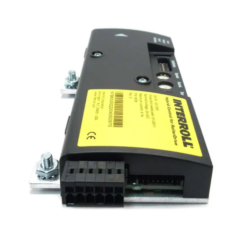
Interroll AdControl User manual

INSPIRED BY EFFICIENCY
Operating Manual
Interroll AdControl

Manufacturer details
Interroll Engineering GmbH
Höferhof 16
42929 Wermelskirchen, Germany
Tel.: +49 (0) 2193 23 0
Fax: +49 (0) 2193 2022
www.interroll.com
Content
We strive for the accuracy, timeliness and completeness of the information and have carefully prepared the contents
in this document. Regardless of this, errors and changes are expressly reserved.
Copyright/industrial property rights
Any texts, images, graphics and the like, as well as their arrangement, are subject to protection under copyright and
other laws of protection. The reproduction, modication, transmission or publication of any part of this document or of
the entire document in any form is prohibited.
The document serves the exclusive purposes of information and of operation in accordance with the regulations and
does not justify any counterfeiting of the products concerned.
All signs contained in this document (protected marks, such as logos and trade names) are the property of Interroll
Holding AG, CH or of third parties and must not be used, copied or distributed without prior written consent.
Online version - only suitable for color printing!

Version 2.0 (12/2019) Online
Translation of the original operating manual 3 von 38
Inhalt
1 About this document 5
1.1 Information about this operating manual 5
1.2 Warning notices in this document 6
1.3 Symbols 7
2 Safety-related information 8
2.1 State of the art 8
2.2 Proper use 8
2.3 Improper use 8
2.4 Qualicationofpersonnel 9
2.5 Dangers 10
Injury to persons 10
Electricity 10
Work environment 10
Faults in operation 10
Maintenance 10
Unintentional start-up 10
2.6 Interface to other devices 11
2.7 Operating modes/operating phases 11
Standard operation 11
Special operation 11
2.8 Applicable documentation 12
3 Product information 13
3.1 Product description 13
Functions 13
Energy feedback 13
Temperature protection 14
3.2 Components 15
3.3 Typenschild 15
3.4 Technical data 16
3.5 Dimensions 16
3.6 DIP-Schalter 17
3.7 Meaning of the LED 18
3.8 Comparison RollerDrive EC310 and EC300 19

4 von 38
Version 2.0 (12/2019) Online
Translation of the original operating manual
Inhalt
4 Transport and storage 24
4.1 Transport 24
4.2 Storage 24
5 Assembly and installation 25
5.1 Warning notices for installation 25
5.2 Assembling the AdControl 25
5.3 Warning notices for electrical installation 26
5.4 Electrical installation 27
5.5 Eingänge und Ausgänge 27
6 Initial startup and operation 28
6.1 Commissioning 28
Pre-commissioning checks 28
Inspection before each commissioning 28
6.2 Operation 28
7 Maintenance and cleaning 29
7.1 Maintenance 29
Checking the AdControl 29
Replacing the AdControl 29
7.2 Cleaning 30
8 Troubleshooting 31
8.1 Troubleshooting 31
9 Decommissioning and disposal 32
9.1 Decommissioning 32
9.2 Disposal 32
10 Appendix 33
10.1 Replacing a RollerDrive EC200 33
10.2 Electrical data of connectors 33
RollerDrive connector 33
Controller Connection 35
10.3 Translation of the original Declaration of Conformity 37

Version 2.0 (12/2019) Online
Translation of the original operating manual 5 von 38
About this document
1 About this document
1.1 Information about this operating manual
The operating manual is part of the Interroll product(s) named on the title and contains important notes and
information on the various operating phases of the product(s) named.
As with all our products, the operating instructions are subject to constant monitoring and will be adapted if necessary.
The current version of these operating instructions can be found on the Internet at www.interroll.com/support/
All information and notes in these operating instructions have been compiled in accordance with the applicable
standards and regulations as well as the state of the art.
For special versions, special contractual agreements and technical documents apply in addition to these operating
instructions.
¾Toensuresafeandfaultlessoperationandtofullanywarrantyclaimsthatmayapply,readthisoperating
manualrstandobserveitsinstructions.
¾Keep this operating manual within close reach of the product(s) named.
¾Pass this operating manual onto every subsequent owner or user.
The manufacturer assumes no liability for damage and malfunctions that occur as a result of non-
compliance with this operating manual.
Should you still have any unanswered questions after reading this operating manual, please contact Interroll
customer service. Contact details for your region can be found online at www.interroll.com/contact/

6 von 38
Version 2.0 (12/2019) Online
Translation of the original operating manual
About this document
1.2 Warning notices in this document
Warning notices are provided in the context in which danger can occur and describe the nature of the danger in
question. They are structured according to the following examples:
SIGNAL WORD
Type and source of hazard
Consequence(s) in the event of non-compliance
¾Measure(s) for avoiding hazard
Signal words indicate the type and severity of the consequences if measures to avoid the hazard are not observed.
DANGER
Denotes an imminent hazard.
If measures to avoid the hazard are not observed, death or severe injury will occur.
¾Preventive measures
WARNING
Denotes a potentially hazardous situation.
If measures to avoid the hazard are not observed, death or severe injury may occur.
¾Preventive measures
CAUTION
Denotes the possibility of a hazardous situation.
If measures to avoid the hazard are not observed, minor or moderate injury may occur.
¾Preventive measures

Version 2.0 (12/2019) Online
Translation of the original operating manual 7 von 38
About this document
NOTE
Denotes a situation that can lead to material damage.
¾Preventive measures
1.3 Symbols
This symbol indicates useful and important information.
üThissymbolindicatesarequirementthatmustbefullledbeforecarryingoutassemblyorrepairwork.
This symbol indicates general information relating to safety.
¾This symbol indicates an action that needs to be performed.
•This symbol indicates a listed item.

8 von 38
Version 2.0 (12/2019) Online
Translation of the original operating manual
Safety-related information
2 Safety-related information
2.1 State of the art
The Interroll AdControl has been constructed with respect to applicable standards and the current state of the art and
has been delivered in a condition that is safe to operate. Nevertheless, hazards can occur as a result of use.
Non-compliance with the instructions in this operating manual can result in life-threatening injuries.
In addition, the applicable local accident prevention regulations for the area of application and general safety
regulations must be adhered to.
2.2 Proper use
The AdControl may only be used in an industrial environment for industrial purposes within the stipulated performance
limitsthataregiveninthetechnicalspecications.
TheAdControlmayonlybeusedinanindustrialenvironmentforindustrialpurposeswithinthedenedperformance
limitsspeciedinthetechnicaldata.
The AdControl can be used if a RollerDrive EC300 (predecessor of the EC310) is to be replaced by a RollerDrive
EC310. The AdControl has a short connection cable with plug. The plug corresponds to that of the EC300 and is
connected to the existing DriveControl EC200/EC300 or extension cable.
By using AdControl a RollerDrive EC310 can be used without changing the existing wiring.
Depending on the gear ratio, the AdControl can also be used when replacing an EC200 with an EC310.
2.3 Improper use
Any use that goes beyond the proper use is considered improper, unless this has been authorised by Interroll
Engineering GmbH where applicable.
The equipment must not be installed in areas in which substances could form explosive atmospheres/dust atmospheres
or for application in the medical/pharmaceutical sector.
It is considered improper use to install the equipment in exposed spaces that are open to potentially adverse weather
conditions,orareasinwhichthetechnologywouldsuerfromtheprevailingclimacticconditionsandcouldpotentially
malfunction as a result.
The AdControl is not intended for use by private end users. The equipment must not be used in a residential
environment without further examination and without the use of EMC protective measures that have been adapted
accordingly.
It must not be used as a safety-relevant component or for performing safety-relevant functions.

Version 2.0 (12/2019) Online
Translation of the original operating manual 9 von 38
Safety-related information
2.4 Qualication of personnel
Non-qualiedpersonnelareunabletoidentifyrisksandarethereforeexposedtohigherlevelsofdanger.
¾Onlyqualiedpersonnelmaybeassignedwiththetasksoutlinedinthisoperatingmanual.
¾The operating company is responsible for ensuring that personal adhere to the locally valid rules and
regulations for working in a safe and risk-aware manner.
This operating manual is intended for the following target audiences:
Operators
Operators are trained in how to operate and clean the Interroll AdControl unit and follow the safety regulations.
Service engineers
The service engineers have a specialist technical education or have successfully completed a training course from the
manufacturer. They carry out repair and maintenance work.
Qualied electricians
Qualiedelectricianshaveaspecialisttechnicaleducation.Moreover,duetotheirknowledgeandexperienceaswell
as knowledge of applicable regulations, they are able to carry out work on electrical equipment in an appropriate
manner. They are able to identify hazards independently and prevent electrical damage to persons and property.
Allworkonelectricalequipmentmustgenerallyonlybeperformedbyaqualiedelectrician.

10 von 38
Version 2.0 (12/2019) Online
Translation of the original operating manual
Safety-related information
2.5 Dangers
Here,youwillndinformationaboutthedierenttypesofdangersordamagethatcanoccurin
connection with the operation of the AdControl.
Injury to persons
¾ Maintenance, installation and repair work on the unit must only be carried out by authorised technical personnel
in compliance with the applicable provisions.
¾ Before switching on the AdControl, ensure that no unauthorised personnel are situated in the vicinity of the
conveyor/conveying system.
Electricity
¾ Installation and repair work must only be carried out when the system has been disconnected from the power
supply.SwitchothepowertotheAdControlandensurethatitcannotbeunintentionallyswitchedonagain.
Work environment
¾ Remove any materials and objects that are not required from the working area.
Faults in operation
¾ Regularly check the AdControl for visible damage.
¾ Ifsmokedevelops,immediatelyswitchothepowertotheAdControlandensurethatitcannotbe
unintentionally switched on again.
¾ Immediately contact specialist personnel to determine the cause of the malfunction.
Maintenance
¾ Sincetheproductinquestionrequiresnomaintenance,itissucienttosimplyexaminetheAdControlforvisible
damage on a regular basis.
¾ Never open up the AdControl.
Unintentional start-up
¾ Ensure that the connected RollerDrive/motors cannot start up unintentionally, particularly during assembly and
maintenance work or in the event of a fault.

Version 2.0 (12/2019) Online
Translation of the original operating manual 11 von 38
Safety-related information
2.6 Interface to other devices
The integration of the AdControl into a conveyor system can create additional potential hazards. Such potential
hazards are not covered by this operating manual and must be analysed during the development, installation and
commissioning of the conveyor system as a whole.
¾Following the integration of the AdControl into a conveyor system, the entire system must be checked for any
new potential hazards that may be present before the conveyor is switched on.
2.7 Operating modes/operating phases
Standard operation
Operation in the installed condition at the end customer as a component in a conveyor in an overall system.
Special operation
Special operation encompasses all operating modes/operating phases that are necessary to guarantee and maintain
safe standard operation.
Special operating mode Comments
Transport/storage -
Assembly/commissioning In de-energised state
Cleaning In de-energised state
Maintenance/repair In de-energised state
Fault location In de-energised state
Troubleshooting In de-energised state
Decommissioning In de-energised state
Disposal -

12 von 38
Version 2.0 (12/2019) Online
Translation of the original operating manual
Safety-related information
2.8 Applicable documentation
In order to ensure proper use of the RollerDrive, additional operating manuals/documentation relating to the
following must be consulted:
• Power supply unit
• RollerDrive
• Description of the conveyor system/unit
Also ensure that you adhere to the information given in the operating manuals of the connected devices.

Version 2.0 (12/2019) Online
Translation of the original operating manual 13 von 38
Product information
3 Product information
3.1 Product description
TheAdControlservesasaninterfacemodicationbetweenaDriveControl200/DriveControl300andaRollerDrive
EC310. If the RollerDrive EC300 of a conveyor is replaced with a RollerDrive EC310, but the DriveControl 200/300
is to remain, the AdControl ensures that the signals (speed and direction of rotation) of a DriveControl 200/300
are converted in such a way that a RollerDrive EC310 can be connected that behaves in exactly the same way as a
RollerDrive EC300. The AdControl can also be used if the RollerDrive EC300 has been actuated without DriveControl.
Functions
Regenerative breaking
When the RollerDrive motor brakes, it acts as a generator and feeds energy back into the power supply. The
AdControl has a built in brake chopper (load resistor) to limit the DC voltage on the connection to a stable level.
Diagnostics
LEDs indicate the operating condition of the AdControl and the RollerDrive as well as the operating voltage (see
„Meaning of the LED”, page 20). An error signal can also be output.
Speed conversion
Because the RollerDrive EC310 has other gear phases just like the RollerDrive EC300, the RollerDrive EC310
wouldrotateatadierentspeedwhenactuatedinthesameway.TheAdControlconvertsthespeedsignalofthe
DriveControl 200/300 in such a way that the RollerDrive EC310 rotates at the same speed as a previously used
RollerDrive EC300.
Energy feedback
When the speed of a rotating RollerDrive is abruptly reduced (e. g. by removing or reducing the start signal at the
DriveControl),theRollerDrivecontinuestorotatebriey(dependingontheweightoftheconveyedgoodsbeing
stopped) and thus functions as a generator. The voltage generated in this way increases the supply voltage of the
RollerDrive. This increased voltage is partly fed to the DC supply (to max. 30 V) and partly converted to heat via a
brake chopper resistance on the DriveControl. The regenerated power is then available for other consumers. The
more precisely 24 V are complied to in the voltage supply the greater the voltage range in which the DC network can
be fed back to.

14 von 38
Version 2.0 (12/2019) Online
Translation of the original operating manual
Product information
Temperature protection
Thebrakechopperresistoristemperature-controlled.If,duetospecicapplicationproperties(e.g.highconveying
weight or high conveying speed), the brake chopper resistance is frequently switched, the DriveControl switches
owhenitbecomestoohot(approx.90°Cinnertemperature).Iftemperatureprotectionisactivated,thisstateis
indicated by the LEDs and no start signal will be transmitted to the RollerDrive. When the DriveControl has cooled
down, the RollerDrive restarts automatically when a signal is pending. The DriveControl cools down quicker if it is
mountedonaatsurface,ideallymetal.
NOTE
DriveControl failure from overheating
¾Do not perform a voltage reset when temperature protection is active.

Version 2.0 (12/2019) Online
Translation of the original operating manual 15 von 38
Product information
3.2 Components
1 RollerDrive connector 4 Marker (changeable)
2 Mounting link with hole for countersunk screw 5 Cover for DIP switches
3 LED Ready und Fault 6 Controller connection
3.3 Typenschild
1 Product name 4 Manufacturer’s address
2 Manufacturer 5 Week and year of production
3 Serial number 6 Article number

16 von 38
Version 2.0 (12/2019) Online
Translation of the original operating manual
Product information
3.4 Technical data
Rated voltage 24 V DC, protected extra-low voltage (PELV)
Voltage range 19 bis 26 V DC (max. reverse polarity protection 30 V)
Current consumption with RollerDrive: up to 5 A
without RollerDrive: 0,5 A
Protectionclassication IP 20
Cooling Convection
Ambient temperature in operation 0°Cto+40°C(32°Fto104°F)
Ambient temperature during transport and
storage
-40°Cto+85°C(-40°Fto185°F)
Air humidity 5 to 95 %, condensation not permissible
condensation not permissible Max. 1000 m (max. 3300 ft)
3.5 Dimensions

Version 2.0 (12/2019) Online
Translation of the original operating manual 17 von 38
Product information
3.6 DIP-Schalter
The DIP switches are used to select the gear ratio of the previously used RollerDrive EC300 and RollerDrive EC310 to
be used in the future. Based on these values, the AdControl determines the necessary change that has to be made to
the speed signal.
In its as-delivered state, the gear ratio EC300 13:1 and EC310 16:1 are set.
DIP switches Meaning
7,85:1 / 13:1 Gear ratio of the RollerDrive EC300
Bit 0, Bit 1, Bit 2, Bit 3 Gear ratio of the RollerDrive EC310 (see below)
Reserve Not occupied
Gear ratio
RollerDrive EC310
DIP switches
Bit 3 Bit 2 Bit 1 Bit 0
9:1 OFF OFF OFF OFF
12:1 OFF OFF OFF ON
16:1 OFF OFF ON OFF
20:1 OFF OFF ON ON
24:1 OFF ON OFF OFF
36:1 OFF ON OFF ON
48:1 OFF ON ON OFF
64:1 OFF ON ON ON
96:1 ON OFF OFF OFF
IfadierentDIPswitchcombinationissetthantheonelistedinthetable,theRollerDrivespeedofrotation
will be set to 0 RPM.

18 von 38
Version 2.0 (12/2019) Online
Translation of the original operating manual
Product information
DIP switches
1 Bit 3 4 Bit 0
2 Bit 2 5 7,85:1 / 13:1
3 Bit 1 6 Reserve
3.7 Meaning of the LED
The LEDs indicate the operating state of the AdControl and the RollerDrive and provide information about the
operating voltage.
LED green Meaning Operating voltage
On steady AdControl ready for operation 19 to 26 V
Flashing RollerDrive rotating/is activated 19 to 26 V
O AdControl not ready for operation
LED green Meaning Operating voltage
On steady fuse in AdControl defective
Flashing slowly 1) • Operating voltage too low or too high
• RollerDrive Error
• RollerDrive faulty or not connected
unter 18 V oder über 26 V
Flashing quickly 2) Abschaltung wegen erhöhter Temperatur
im Chopperwiderstand
1)LEDashingslowly=0,5son-1,5so
2)LEDashingquickly=0,5son-0,5so

Version 2.0 (12/2019) Online
Translation of the original operating manual 19 von 38
Product information
3.8 Comparison RollerDrive EC310 and EC300
Replacing a RollerDrive EC300 with a RollerDrive EC310 changes the torque and maximum speed.
Gear ratio DIP switches Nominal
torque [Nm]
Max. torque
[Nm]
Max. speed
[m/s]
EC300 EC310 Bit 3 Bit 2 Bit 1 Bit 0 7,85:1
/ 13:1 EC300 EC310 EC300 EC310 EC300 EC310
13:1 12:1 OFF OFF OFF ON ON 0,90 0,61 1,60 1,46 1,27 1,31
13:1 16:1 OFF OFF ON OFF ON 0,90 0,81 1,60 1,95 1,27 0,98
13:1 20:1 OFF OFF ON ON ON 0,90 1,01 1,60 2,44 1,27 0,78
7,85:1 9:1 OFF OFF OFF OFF OFF 0,70 0,45 1,00 1,10 2,00 1,75
7,85:1 12:1 OFF OFF OFF ON OFF 0,70 0,61 1,00 1,46 2,00 1,31
7,85:1 16:1 OFF OFF ON OFF OFF 0,70 0,81 1,00 1,95 2,00 0,98

20 von 38
Version 2.0 (12/2019) Online
Translation of the original operating manual
Product information
The following graphs show the conveyor speed as a function of the voltage and of the gear stages.
Abbreviations:
• v [m/s] Conveyor speed in m/s
• U [V] Speed control in volts
EC300 13:1
Table of contents
Other Interroll Controllers manuals
Popular Controllers manuals by other brands
Allen-Bradley
Allen-Bradley CompactLogix 5370 L1 quick start
select solar
select solar EPHC 10A Instruction guide
Yamaha
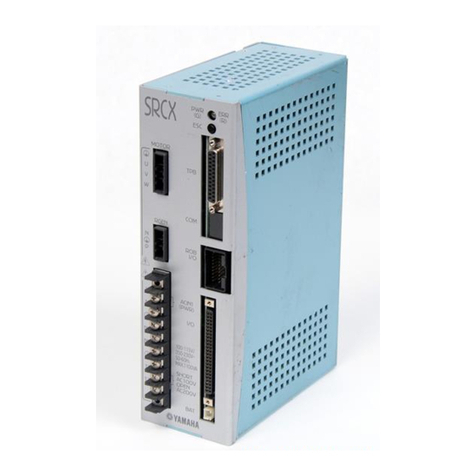
Yamaha SRCD Series Supporting supplement manual

Mitsubishi Electric
Mitsubishi Electric FX3G-2EYT-BD user manual
FUHR
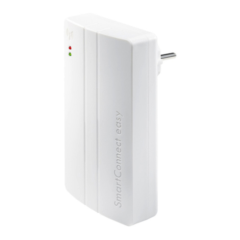
FUHR SmartConnect easy Operation manual
MDT Technologies
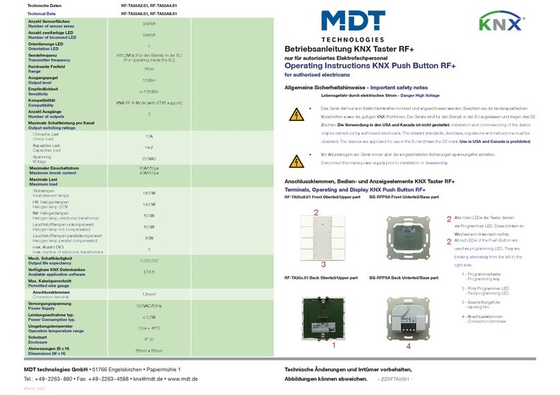
MDT Technologies RF-TA55A2.01 operating instructions
Hitachi
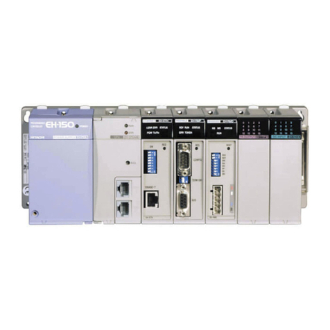
Hitachi EH-150 Series instruction manual
Greenheck
Greenheck MP-323 Field installation instructions
Carrier
Carrier XCT 7 40VCI67FQEE Installation and owner's manual

Lab.gruppen
Lab.gruppen NLB 60E supplementary guide
HIFEI Technology
HIFEI Technology SwordfishX 200A-8S instructions
Matrox
Matrox QuadHead2Go Q2G-DP4K Configuration guide
