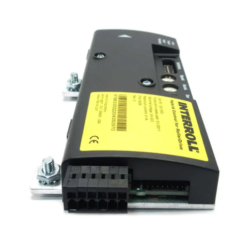
Interroll MultiControl Owner's manual

Supplementary Document
Interroll MultiControl
Operating and Programming

Operating and Programming I
Table of content
1About this document..........................................................................................................................................1
1.1 Information about this supplementary document......................................................................................1
1.2 Symbols.................................................................................................................................................................2
1.3 Data types............................................................................................................................................................2
2Description............................................................................................................................................................3
3Configuration options .......................................................................................................................................4
4Configure MultiControl.....................................................................................................................................5
4.1 The Magnetic Sensor.........................................................................................................................................5
Select function.....................................................................................................................................................5
LED displays when using the magnetic sensor...........................................................................................7
4.2 Service Data Objects (SDO)...........................................................................................................................9
Version information ...........................................................................................................................................9
Manufacturer information................................................................................................................................9
Diagnostic information...................................................................................................................................10
Error information.............................................................................................................................................11
Network online time .......................................................................................................................................11
Control program information ......................................................................................................................12
Bus parameter..................................................................................................................................................13
Motor settings...................................................................................................................................................15
Inputs and Outputs.........................................................................................................................................18
Application module.........................................................................................................................................19
Error handling ..................................................................................................................................................20
5Description of the control programs..........................................................................................................22
ZPA programs with stop function for straight sections and curves...................................................22
5.1 ZPA Single Release.........................................................................................................................................23
Timer...................................................................................................................................................................23
PLC references according to process image "Universal Full" (see process data) .........................24
5.2 ZPA Train Release...........................................................................................................................................26
Timer...................................................................................................................................................................26
PLC references according to process image "Universal Full" (see process data) .........................27

II Operating and Programming
Handover (Handshake Signals)...................................................................................................................29
5.3 ZPA Transfer In ................................................................................................................................................31
Timer...................................................................................................................................................................32
PLC references according to process image "Universal Full" (see process data) .........................32
Merge prioritization........................................................................................................................................34
Handover (Handshake-Signals)...................................................................................................................35
5.4 ZPA Transfer Out............................................................................................................................................37
Timer...................................................................................................................................................................38
PLC references according to process image "Universal Full" (see process data) .........................38
Merge prioritization........................................................................................................................................40
Handover (Handshake-Signals)...................................................................................................................41
5.5 ZPA Merge........................................................................................................................................................43
Timer...................................................................................................................................................................43
PLC references according to process image "Universal Full" (see process data) .........................44
Merge prioritization........................................................................................................................................45
Handover (Handshake-Signals)...................................................................................................................47
5.6 ZPA HPD (High Performance Divert) .........................................................................................................48
Timer...................................................................................................................................................................48
PLC references according to process image "Universal Full" (see process data) .........................49
Merge prioritization........................................................................................................................................51
Handover (Handshake-Signals)...................................................................................................................52
5.7 Semi-automatic programs ............................................................................................................................54
5.8 HPD Semi-Automatic......................................................................................................................................54
Timer...................................................................................................................................................................54
PLC references according to process image "Universal Full" (see process data) .........................55
5.9 Transfer Semi-Automatic...............................................................................................................................57
Timer...................................................................................................................................................................57
PLC references according to process image "Universal Full" (see process data) .........................58
5.10 I/O Device.........................................................................................................................................................60
5.11 Specific parameters (only Transfer and HPD) in the I/O device .......................................................61
Transfer..............................................................................................................................................................61

Operating and Programming III
PLC references according to process image "Universal Full" (see process data) .........................61
HPD .....................................................................................................................................................................62
PLC references according to process image "Universal Full" (see process data) .........................62
6Description of the service functions............................................................................................................64
6.1 Teach-in..............................................................................................................................................................64
Prerequisites......................................................................................................................................................65
Basic setting of the MultiControl.................................................................................................................65
Reading the motors.........................................................................................................................................65
Assign Slave RollerDrive................................................................................................................................66
Abort the Teach-in procedure.....................................................................................................................67
Configuring the sensors.................................................................................................................................67
6.2 Plug&Play...........................................................................................................................................................68
6.3 Plug&Play semi-automatic.............................................................................................................................69
7Examples of applications...............................................................................................................................70
7.1 Example 1: Conveyor with three MultiControl.......................................................................................70
7.2 Example 2: Conveyor and Transfer with five MultiControl ................................................................72
7.3 Example 3: Start sensor ................................................................................................................................74
7.4 Example 4: Stop of Zone 3..........................................................................................................................75
8Process data .....................................................................................................................................................76
8.1 Process image of the inputs..........................................................................................................................76
Sensors...............................................................................................................................................................76
Digital I/O .........................................................................................................................................................77
Motor State.......................................................................................................................................................78
System Status ...................................................................................................................................................79
Additional signals............................................................................................................................................79
8.2 Process image of the outputs.......................................................................................................................82
Digital outputs..................................................................................................................................................82
Motors................................................................................................................................................................82
8.3 Different process images...............................................................................................................................86
Comparison of the process images............................................................................................................86
PII, Process Image „Universal Full“ ..............................................................................................................88

IV Operating and Programming
PIO, Process Image „Universal Full“............................................................................................................92
PII, Process Image „Universal Compact“ ...................................................................................................95
PIO, Process Image „Universal Compact“.................................................................................................99
PII, Process Image „I/O Mode“................................................................................................................. 103
PIO, Process Image „I/O Mode“.............................................................................................................. 105
PII, Process Image „Control Mode“.......................................................................................................... 106
PIO, Process Image „Control Mode“....................................................................................................... 110
PII, Process Image „I/O Mode Tiny“........................................................................................................ 114
PIO, Process Image „I/O Mode Tiny“..................................................................................................... 116
PIO, Process Image „Position Mode“....................................................................................................... 117
9I/O configuration ......................................................................................................................................... 118
10 Interface Box for VDC Motors.................................................................................................................. 120
DIP switch of the Interface Box................................................................................................................. 121
11 Signal flow...................................................................................................................................................... 122

About this document
Operating and Programming 1
1 About this document
1.1 Information about this supplementary document
The supplementary document describes the operation, the integrated programs and the
interfaces of the Interroll MultiControl.
In the further course, the term "control" is used alternatively.
The latest version of this document is available on the Internet at:
www.interroll.com/support/
All information and instructions in this document have been compiled taking into account the
applicable standards and regulations as well as the state of the art.
➢For trouble-free and safe operation and the fulfilment of any warranty claims, first read
the user manual and follow the instructions.
The manufacturer assumes no liability for damage and malfunctions resulting from
non-compliance with this document.
If you still have questions after reading this document, contact Interroll Customer
Service. Contact persons in your area can be found on the internet at
www.interroll.com/contact/

2 Operating and Programming
1.2 Symbols
This symbol indicates useful and important information.
✓This symbol indicates a prerequisite that must be met before installation or maintenance
work.
This symbol represents general safety-related information.
➢This symbol marks the steps to be carried out.
•This symbol stands for enumerations.
1.3 Data types
The following data types are used for cyclic and acyclic communication with the MultiControl:
Shortcut
Data type
Description
BOOL
Boolean
Truth value (true / false)
BYTE
Byte
Bit sequence with 8 bits
SINT
Short Integer
Integer variable with 8 bits
USINT
Unsigned Short Integer
Positive integer variable with 8 bits
INT
Integer
Integer variable with 16 bits
UINT
Unsigned Integer
Positive integer variable with 16 bits
DINT
Double Integer
Integer variable with 32 bits
UDINT
Unsigned Double Integer
Positive integer variable with 32 bits
LINT
Long Integer
Integer variable with 64 bits
STRING
String
Character string with a maximum of 31
characters

Description
Operating and Programming 3
2 Description
The MultiControl can be operated in different operating modes:
•as I/O device (fully PLC controlled)
•semi-automatic (partly PLC-controlled)
•fully automatic (without PLC)
A MultiControl can control up to four RollerDrive with different speeds, accelerations and
decelerations. In addition to the four sensor inputs, four inputs or outputs can be freely
configured.
Depending on the selected ZPA program (Zero Pressure Accumulation), the delivery process can
be influenced by a PLC. In operation as an I/O device, a PLC controls the motors without any
program influence.
Each MultiControl controls up to four zones. One zone corresponds to a conveyor section
consisting of RollerDrive, rotating rollers and the corresponding sensors and switches. Depending
on the selected ZPA program, up to three Slave-RollerDrive can be assigned.
The combination of a MultiControl with the associated zones, RollerDrive and sensors is called a
"module".
To configure larger conveying systems, multiple modules can be linked together. For this purpose,
different IP addresses are assigned to the MultiControls. The connection to additional conveying
systems is realized, for example, by configurable inputs/outputs. Data is exchanged with a
master control system (PLC) via the fieldbus systems "PROFINET", "EtherNet/IP" or "EtherCAT".
EtherCAT is only applicable as an I/O device.

Configuration options
4 Operating and Programming
3 Configuration options
To commission the MultiControl, it must first be configured. This can be done in different ways:
•All settings can be configured via a web-based user interface on a computer connected to
the MultiControl (see "Interroll MultiControl Instruction Manual")
•Using the magnetic sensor, the sensors, the bus type and the LED displays can be
configured directly on the MultiControl, as well as the MultiControl can be tested,
automatically configured or reset to the factory settings (see "The Magnetic Sensor", page
5)
•Service Data Objects (SDO) written by a higher-level controller can be used to configure
all settings except the bus type (see "Service Data Objects (SDO)", page 9)
•The station name, IP configuration and connection settings can be changed via a PLC
development environment

Configure MultiControl
Operating and Programming 5
4 Configure MultiControl
4.1 The Magnetic Sensor
An optional magnet (see Interroll MultiControl Instruction Manual / Appendix / Accessories)
activates the built-in magnetic sensor.
The magnetic sensor is located on the top side of the MultiControl, between the two "R" of the
"INTERROLL" lettering just before the base plate (see Interroll MultiControl Instruction Manual /
Product Information / Structure).
The magnetic sensor can be used to perform the following functions:
•Select sensors
•Select bus type
•Perform teach-in procedure
•Turn on/off the LED indicators of the sensors / I/O
•Reset MultiControl to factory settings
Select function
➢Hold magnet to the magnetic sensor.
When the magnetic sensor detects the magnet, the "Fault" LED lights up permanently. After
one second, a running light starts in the LED bar on the left side of the MultiControl.
Each LED is assigned a function:
No.
LED
Function
1
Sensor 1
Cancel
2
I/O 1
Select sensors
3
RD 1
Select bus type
4
RD 2
Perform teach-in procedure
5
Sensor 2
Turn on/off the LED indicators of the sensors / I/O
6
I/O 2
Reset MultiControl to factory settings

Configure MultiControl
6 Operating and Programming
➢To select a function, remove the magnet when the corresponding LED is lit..
Two seconds after removing the magnet, the selection is accepted. During this time, the
"Ready" and "Com" LEDs and the LED belonging to the selection flash. If a second
selection belongs to this function, the LED of the previous selection flashes for approx.
Seven seconds.
➢To select this second selection, hold the magnet back to the magnetic sensor after two
seconds.
A running light starts in the LED bar on the right side of the MultiControl.
Function
Selection
Selection No.
LED
2: Select sensors
PNP Normally Closed
1
Sensor 3
NPN Normally Closed
2
I/O 3
PNP Normally Open
3
RD 3
NPN Normally Open
4
RD 4
3: Select bus type
EtherCAT
1
Sensor 3
PROFINET
2
I/O 3
EtherNet/IP
3
RD 3
4: Perform teach-in
procedure
Read motors
1
I/O 3
Start teach-in
2
RD 4
Cancel teach-in
3
Sensor 3
6: Reset MultiControl to
factory settings
Confirmation
I/O 4
➢To accept the second selection, remove the magnet when the corresponding LED is lit. The
selection is accepted five seconds after removing the magnet.
If the EtherCAT bus type is selected, the user interface can no longer be used after
the restart since this bus type does not support it.

Configure MultiControl
Operating and Programming 7
LED displays when using the magnetic sensor
When the magnetic sensor detects the magnet, the "Fault" LED lights up permanently. If the
setting via the magnetic sensor is activated, the "Ready" and "Com" LEDs also flash at 1 Hz.
LED
State
Definition
Sensor 1
On
Setting function 1: Cancel
I/O 1
On
Setting function 2: Select Sensors
I/O 1 +
Sensor 3
On
Selection 1 for setting function 2: Sensors PNP Normally
Closed
I/O 1 +
I/O 3
On
Selection 2 for setting function 2: Sensors NPN Normally
Closed
I/O 1 +
RD 3
On
Selection 3 for setting function 2: Sensors PNP Normally
Open
I/O 1 +
RD 4
On
Selection 4 for setting function 2: Sensors NPN Normally
Open
RD 1
On
Setting function 3: Select bus type
RD 1 +
Sensor 3
On
Selection 1 for setting function 3: EtherCAT
RD 1 +
I/O 3
On
Selection 2 for setting function 3: PROFINET
RD 1 +
RD 3
On
Selection 3 for setting function 3: EtherNet/IP
RD 2
On
Setting function 4: Teach-in procedure
RD 2 +
Sensor 3
On
Selection 1 for setting function 4: Read motors
RD 2 +
I/O 3
On
Selection 2 for setting function 4: Start teach-in
RD 2 +
RD 3
On
Selection 3 for setting function 4: Cancel teach-in

Configure MultiControl
8 Operating and Programming
LED
State
Definition
Sensor 2
On
Setting function 5: Switch on/off the LED displays of the
sensors / I/O
I/O 2
On
Setting function 6: Reset MultiControl to factory settings
I/O 2 +
I/O 4
On
Confirm setting function 6: Reset MultiControl to factory
settings
Sensor 3
Flashes 1 Hz
EtherCAT stack is being loaded
I/O 3
Flashes 1 Hz
PROFINAT stack is being loaded
RD 3
Flashes 1 Hz
EtherNet/IP stack is being loaded
Together with the following displays the LED "Ready" and "Com" flash with 2 Hz, the LED "Fault"
is off.
LED
State
Definition
RD 1
Sensor 3
On
Flashes 2 Hz
Selection "EtherCAT" active, magnetic sensor not activated
(anymore)
RD 1
I/O 3
On
Flashes 2 Hz
Selection "PROFINET" active, magnetic sensor not
activated (anymore)
RD 1
RD 3
On
Flashes 2 Hz
Selection "EtherNet / IP" active, magnetic sensor not
activated (anymore)
I/O 2
I/O 4
On
Flashes 2 Hz
Confirmation of setting function 6: Reset selected, magnetic
sensor not pressed (anymore)

Configure MultiControl
Operating and Programming 9
4.2 Service Data Objects (SDO)
Almost all settings of the MultiControl (except for the bus type) can be changed via acyclic
communication. This communication corresponds to the service data objects (SDO) of the
CANopen protocol. Access is possible via the RDREC and WRREC functions in accordance with
IEC 61131-3.
The SDOs are subdivided into indices and sub-indices. For configuration via EtherCAT systems,
the index and sub-index are separated by a colon (e.g. index 0x4700, sub-index A becomes
0x4700:0A). When accessing via PROFINET and EtherNet/IP, the index and sub-index must be
added together (e.g. 0x4700, sub-index A becomes 0x470A).
Version information
SDO-Index 0x4000
Sub-index
Description
Data type
Access
Comment
1
Hardware
STRING
R
2
Application
Software
STRING
R
3
System Software
STRING
R
4
Network Software
STRING
R
Manufacturer information
SDO-Index 0x4100
Sub-index
Description
Data type
Access
Comment
1
Serial Number
STRING
R
2
Manufacture Date
STRING
R

Configure MultiControl
10 Operating and Programming
Diagnostic information
SDO-Index 0x4200
Sub-index
Description
Data type
Access
Comment
1
Motor Voltage
Act. [mV]
INT
R
Effective motor supply
voltage
2
Motor Voltage
Max. [mV]
INT
R
Maximum motor supply
voltage
3
Motor Voltage
Min. [mV]
INT
R
Minimum motor supply
voltage
4
Logic Voltage
Act. [mV]
INT
R
Effective logic supply
voltage
5
Logic Voltage
Max. [mV]
INT
R
Maximum logic supply
voltage
6
Logic Voltage
Min. [mV]
INT
R
Minimum logic supply
voltage
7
Temperature
Act. [dC]
INT
R
Effective temperature
8
Temperature
Max. [dC]
INT
R
Maximum Temperature
9
Temperature
Min. [dC]
INT
R
Minimum Temperature

Configure MultiControl
Operating and Programming 11
Error information
SDO-Index 0x4300
Sub-index
Description
Data type
Access
Comment
1
Error State
BYTE
R
1 = In operation
2 = Non-critical error
3 = Critical error
2
Error Code
UINT
R
Error code oft he last error
(0 = no error)
3
Time Motor
Error 1
UDINT
R
Time since last error
motor 1
4
Time Motor
Error 2
UDINT
R
Time since last error
motor 2
5
Time Motor
Error 3
UDINT
R
Time since last error
motor 3
6
Time Motor
Error 4
UDINT
R
Time since last error
motor 4
Network online time
SDO-Index 0x4400
Sub-index
Description
Data type
Access
Comment
0
Network Online
Time
UDINT
R
Operating time of the bus

Configure MultiControl
12 Operating and Programming
Control program information
SDO-Index 0x4500
Sub-index
Description
Data type
Access
Comment
1
Selected State
Table
UINT
R
Selected application
program
2
Version Year
UINT
R
Version of application
program
3
Version Month
USINT
R
4
Version Day
USINT
R
5
Version Hour
USINT
R
6
IO 1 Usage
BYTE
R
IO 1 is used in the selected
application program
7
IO 2 Usage
BYTE
R
IO 2 is used in the selected
application program
8
IO 3 Usage
BYTE
R
IO 3 is used in the selected
application program
9
IO 4 Usage
BYTE
R
IO 4 is used in the selected
application program

Configure MultiControl
Operating and Programming 13
Bus parameter
SDO-Index 0x4600
Sub-index
Description
Data type
Access
Comment
1
Bus Type
USINT
R
Used Bus type:
1 = EtherCAT
2 = PROFINET
3 = EtherNet/IP
2
IP Configuration
Mode
USINT
R/W
Configuration mode of the
address:
1 = Static
2 = BOOTP
3 = DHCP
3
IP Address
UDINT
R/W
Own IP address
4
IP Network Mask
UDINT
R/W
Subnet mask
5
IP Gateway
Address
UDINT
R/W
IP-Address Default
Gateway
6
IP Address DNS
1
UDINT
R/W
IP-Address Domain Name
Server #1
7
IP Address DNS
2
UDINT
R/W
IP-Address Domain Name
Server #2
8
IP Host Name
STRING
R/W
IP Host Name
9
IP Domain Name
STRING
R/W
IP Domain Name
A
ACD Enable
BOOL
R/W
Identification of address
conflicts (EtherNet/IP)
B
Quick Start up
Enable
BOOL
R/W
QuickStart (PROFINET)

Configure MultiControl
14 Operating and Programming
Sub-index
Description
Data type
Access
Comment
C
IP Address
Neighbour 1
UDINT
R/W
IP address of neighbours
using ZPA and ZPA +
D
IP Address
Neighbour 2
UDINT
R/W
E
IP Address
Neighbour 3
UDINT
R/W
F
IP Address
Neighbour 4
UDINT
R/W
10
IP Address
Neighbour 5
UDINT
R/W
11
IP Address
Neighbour 6
UDINT
R/W
12
IP Address
Neighbour 7
UDINT
R/W
13
IP Address
Neighbour 8
UDINT
R/W
14
Big Endian
Format
BOOL
R/W
PLC data is in big-endian
format (MSB first)
15
USINT
RO
16
USINT
RO
17
BOOL
R/W
If the EtherCAT bus type is selected, the user interface can no longer be used after
the restart since this bus type does not support it.

Configure MultiControl
Operating and Programming 15
Motor settings
SDO-Index 0x4700
Sub-index
Description
Data
type
Access
Comment
Min.
Max.
1
Motor Type 1
USINT
R/W
Motor type at
connection RD1:
1 = None
2 =
VDC_SPEED
3 =
VDC_POSITION
Setting 2 and 3
currently not
supported.
0
3
2
Motor Type 2
USINT
R/W
Motor type at
connection RD2
0
3
3
Motor Type 3
USINT
R/W
Motor type at
connection RD3
0
3
4
Motor Type 4
USINT
R/W
Motor type at
connection RD4
0
3
5
Direction CW
1
BOOL
R/W
True =
RollerDrive turns
clockwise
False =
RollerDrive turns
counter
clockwise
6
Direction CW
2
BOOL
R/W
7
Direction CW
3
BOOL
R/W
8
Direction CW
4
BOOL
R/W
9
Diameter 1
[mm]
UINT
R/W
Roller Diameter
RollerDrive
30
100
A
Diameter 2
[mm]
UINT
R/W
B
Diameter 3
[mm]
UINT
R/W
Other manuals for MultiControl
2
Table of contents
Other Interroll Controllers manuals
Popular Controllers manuals by other brands

Emerson
Emerson AS1-FRE Series RE-ASSEMBLY INSTRUCTIONS

FGH
FGH Series1000 Operator's manual
Filtration Group
Filtration Group MFS-05 Translation of the original instructions

Casambi
Casambi NB. 1 quick start guide
Athena Controls
Athena Controls 16C Series Operation manual
Trane
Trane Tracer UC400 installation guide

