manuals.online logo
Brands
  1. Home
  2. •
  3. Brands
  4. •
  5. Greenheck
  6. •
  7. Controllers
  8. •
  9. Greenheck MP-323 User manual

Greenheck MP-323 User manual

Other Greenheck Controllers manuals
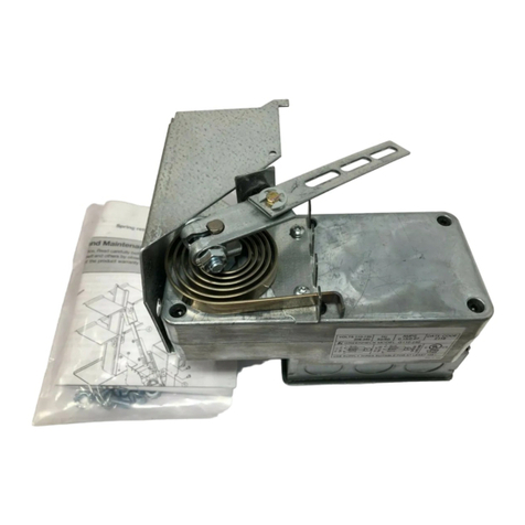
Greenheck 331-2856 Installation and operating instructions

Greenheck

Greenheck 331-2856 Installation and operating instructions

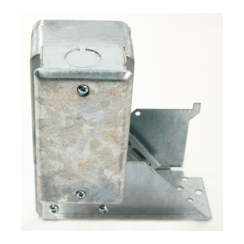
Greenheck MP-220A User manual

Greenheck

Greenheck MP-220A User manual

Greenheck Microprocessor Controller User manual

Greenheck

Greenheck Microprocessor Controller User manual

Greenheck vari-green Installation and operating instructions

Greenheck

Greenheck vari-green Installation and operating instructions

Greenheck MP-210 User manual

Greenheck

Greenheck MP-210 User manual

Greenheck MP-310 User manual

Greenheck

Greenheck MP-310 User manual

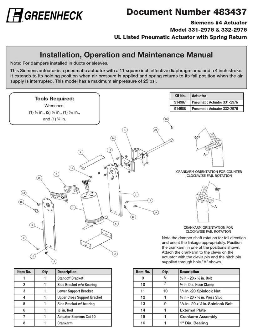
Greenheck 331-2976 Installation and operating instructions

Greenheck

Greenheck 331-2976 Installation and operating instructions

Greenheck MSXX04 Series User manual

Greenheck

Greenheck MSXX04 Series User manual

Greenheck HOA Troubleshooting guide

Greenheck

Greenheck HOA Troubleshooting guide

Greenheck MP-210 User manual

Greenheck

Greenheck MP-210 User manual

Greenheck PGD1000W00 User manual

Greenheck

Greenheck PGD1000W00 User manual
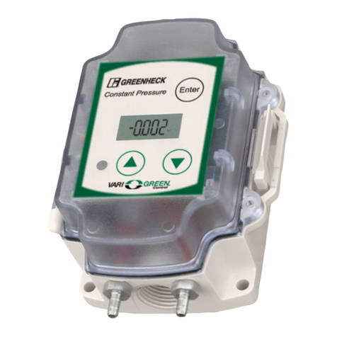
Greenheck HVLS Series User manual

Greenheck

Greenheck HVLS Series User manual

Greenheck DOAS v8.1 User manual

Greenheck

Greenheck DOAS v8.1 User manual

Greenheck MP-310 User manual

Greenheck

Greenheck MP-310 User manual

Greenheck Belimo Actuators Direct Drive Series User manual

Greenheck

Greenheck Belimo Actuators Direct Drive Series User manual

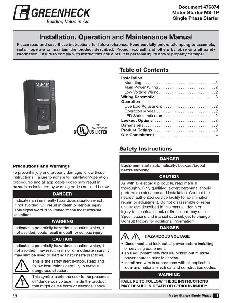
Greenheck MS-1P User manual

Greenheck

Greenheck MS-1P User manual

Greenheck 474706 User manual

Greenheck

Greenheck 474706 User manual

Greenheck KFCC User manual

Greenheck

Greenheck KFCC User manual

Greenheck MP-100A User manual

Greenheck

Greenheck MP-100A User manual
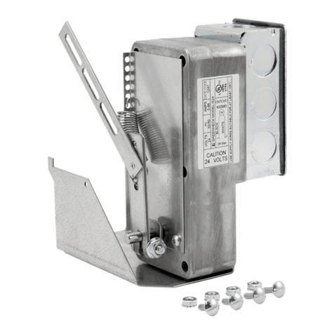
Greenheck HVLS User manual

Greenheck

Greenheck HVLS User manual

Popular Controllers manuals by other brands

Sunricher SR-ZV9003T3-RGBW-US Installation

Sunricher

Sunricher SR-ZV9003T3-RGBW-US Installation

Ksenia intro Installation and configuration manual

Ksenia

Ksenia intro Installation and configuration manual

Inovance CAN200 Series manual

Inovance

Inovance CAN200 Series manual

Gauzy LC6 FLEX Controller Installation and operation guide

Gauzy

Gauzy LC6 FLEX Controller Installation and operation guide

Viking SLP-1 Technical practice

Viking

Viking SLP-1 Technical practice

CKD KBX-30E-U Series instruction manual

CKD

CKD KBX-30E-U Series instruction manual

Sharp Energy Sun Flux User manual & installation guide

Sharp Energy

Sharp Energy Sun Flux User manual & installation guide

Yamaha RCX40 user manual

Yamaha

Yamaha RCX40 user manual

AB Quality PowerFlex 400 Frames D-H Service bulletin

AB Quality

AB Quality PowerFlex 400 Frames D-H Service bulletin

Yamaha MJC8 owner's manual

Yamaha

Yamaha MJC8 owner's manual

AL-KO ATC operating instructions

AL-KO

AL-KO ATC operating instructions

Savant SmartControl 2 Deployment guide

Savant

Savant SmartControl 2 Deployment guide

GameSir T3S user manual

GameSir

GameSir T3S user manual

Kostal inveor operating manual

Kostal

Kostal inveor operating manual

Emerson Yarway 20-55 Operating and safety instructions

Emerson

Emerson Yarway 20-55 Operating and safety instructions

CoCo ACM-LV24 Quick installation guide

CoCo

CoCo ACM-LV24 Quick installation guide

Brooks SLA5810/20 Installation and operation manual

Brooks

Brooks SLA5810/20 Installation and operation manual

SIGMA TEK SR 011 Technical manual

SIGMA TEK

SIGMA TEK SR 011 Technical manual

manuals.online logo
manuals.online logoBrands
  • About & Mission
  • Contact us
  • Privacy Policy
  • Terms and Conditions

Copyright 2025 Manuals.Online. All Rights Reserved.

MP-323 01-97
Motor Pack Contents
1. Actuator
2. Actuator Bracket
3. Actuator Arm Assembly
4. Connecting Links
5. Actuator Spring
All necessary hardware included
Actuator Specifications
The MP-323 motor pack uses a single phase, 60hz, shaded
pole, stall type impedance protected electric actuator.
Specific model depends on the voltage selected.
Greenheck Part #453446
Black
Black
Green
Actuator Wiring Diagram
L1
L2
M
Field Installation Instructions for
Multi Products
MP-323 Motor Pack
UL Listed Electric Actuators With Spring Return
For Use With WD-323 Dampers
VENCO PRODUCTS
GREENHECK
®
1. The MP-323 motor pack is designed for installation on
Model WD-323 backdraft dampers only. When properly
installed, the damper will be vertically mounted to
exhaust air.
2. Position the motor bracket into the inside lower left
corner of the damper.
3. While holding the bracket snug into the corner and
keeping it square to the damper frame, trace the
location of the two mounting holes onto the damper
frame.
4. Mount the motor pack to the damper frame using
hardware provided.
5. Connect the motor arm to the blade as shown in Detail
“A”.
6. With the blades in the fully open position, rotate the
motor arm away from the damper until it seats firmly
against the rubber stop. Hold the arm in this postion
while tightening the two adjustment screws on the
motor linkage. (Adjustment screws should be placed as
far apart as possible to provide greater stability to the
linkage.)
7. Release the motor arm to allow the blades to close.
8. If the damper fails to function properly, check for one of the
following causes:
A. Motor pack fails to close the damper completely.
• Check for an ‘out of square’ or racked damper.
• Insufficient spring tension.
B. Motor pack fails to open the damper completely.
• Check for an ‘out of square’ or racked damper.
• Excessive spring tension.
• Excessive voltage drop.
C. Motor pack fails to function.
• Check for correct voltage.
• Check for proper wiring.
Detail "A"
Adjustment Screws
Mounting Hardware
Wiring Diagram
Black
Black
Green
L1
L2
M
Motor Packs MP-323 Voltages
Are 1-ø, 60 Hz 24 115 230 440
Speed (RPM) 1.8 1.8 1.8 1.8
Running Amps 1.4 0.22 0.12 0.065
Stall Amps 1.6 0.24 0.14 0.075
Identification # 2651 UL-2-2469 UL-3-2495 UL-4-2576
Greenheck's MP-323 motor packs utilize single phase, 60 HZ (50 HZ optional) damper actuators and are supplied in one of the
following voltages: 24, 115, 230, or 440 volts. The voltage of the actuator is stamped into the housing near the output shaft. For
277, 575 or 600 volt operation, an optional transformer and a 115 volt motor pack is required. The 230 volt model can also be
used for 208 volt applications.
1. Diagrams are shown for motor packs and dampers installed with powered ventilator fan equipped with a single speed
motor. The damper will open when the fan is on and close when the fan is off. For connection to 2-speed motors or for
other control sequences consult the factory.
2. Diagrams shown with end switches are for applications where it is desirable to have the damper fully open before fan
start-up.
220, 277, 440, 575 or 600 volts
115 or 220 volts - with End Switch
(Requires end switch kit #851038 installed on damper)
220, 277, 440, 575 or 600 volts with End Switch
(Requires end switch kit#851038 installed on damper)
575/600 Volt Transformer
Model B050WZ13
208/220/277/480 Volt Transformer
Model AE-249
Single Phase
Three Phase
Transformers
Black
Black
Green Actuator
Fuse (if required)
Safety Disconnect
*Fan Starter
Manual or Magnetic
115v Neutral
(white) Conductor
* For 115v starters, neutral (white)
conductor is not opened or fused.
1O
Fan
Motor
L1
L2
Black
Black
Green
Actuator
Fuse
(if required)
Safety Disconnect
*Magnetic Fan
Starter
115v Neutral
(white)
Conductor
1O
Fan
Motor
L1
L2
End
Switch
M
Fan
On-Off
Switch
NC
C
NO
* For 115v starters, neutral (white)
conductor is not opened or fused.
Black
Black
Green
Actuator
Fuse
(if required)
Safety Disconnect
3O
Fan
Motor
L1
L2
End
Switch
M
Fan
On-Off
Switch
Optional transformer for
277, 575 or 600 volts
(115v motorpack required)
L3
Fan Starter
Manual or Magnetic
NC
C
NO
Black
Black
Green
Actuator
Fuse (if required)
Safety Disconnect
Fan Starter
Manual or Magnetic
Optional transformer for
277, 575 or 600 volts
(115v motorpack required)
3O
Fan
Motor
L1
L2
L3
115 or 220 volts
Black
Black
Green
Connect common wire and one color
coded wire corresponding to supply
voltage of source. Insulate all unused
primary wires.
Common (white)
208v (Red)
220v (Green)
277v (Brown)
480v (Blue)
208/220/277/480 Volt Primary
115 volt secondary
H1
H2
X2
X1
110v
115v
120v
Secondary
600v
575v
550v
Primary
TYPICAL WIRING DIAGRAMS MP-323