Interroll BM 8350 User manual

Installation and Operating Instructions
Interroll 24 V Belt Conveyor
Straight / curve
BM 8350 / BM 8360
Version 1.1 (02/2016) en-US
Translation of original instruction manual

Manufacturer's address
Interroll Automation GmbH
Dietmar-Hopp-Straße 3
74889 Sinsheim (Germany)
Ph.: +49 7261 938 – 0
Fax: +49 7261 938 – 124
www.interroll.com
Copyright of installation and operating instructions
The copyright of these installation and operating instructions remains with Interroll
Automation GmbH. The installation and operating instructions contain technical
regulations and drawings which may not be reproduced partially or in full, transmitted by
any means, utilized without permission for competitive purposes or disclosed to third
parties.
IAD - BA - 1741
Interroll T. Nr. 1103990
Version 1.1 (02/2016) en-US
Translation of original instruction manual

Interroll 24 V belt conveyor straight / curve
BM 8350 / BM 8360
Version 1.1 (02/2016) en-US
Translation of original instruction manual
3
Table of contents
Introduction.....................................................................................................................6
Notes about working with the installation and operating instructions...............................6
Contents of these installation and operating instructions ................................................6
Integrated part of the product ................................................................................................6
Installation and operating instructions are part of the module......................................6
Warning notices in this document ................................................................................................7
Symbols ...............................................................................................................................................7
Safety ..............................................................................................................................8
State of the art..................................................................................................................................8
Intended use.......................................................................................................................................8
Field of use....................................................................................................................................8
Changes to the module .............................................................................................................8
Personnel qualification.....................................................................................................................8
Operators......................................................................................................................................8
Service personnel........................................................................................................................8
Electricians.....................................................................................................................................8
Dangers ...............................................................................................................................................9
Safety devices..............................................................................................................................9
Electricity........................................................................................................................................9
Rotating parts...............................................................................................................................9
Parts lying around or falling off ..............................................................................................9
Risk of injury due to faults during operation .......................................................................9
Maintenance intervals................................................................................................................9
Interfaces to other devices.............................................................................................................9
Operating modes ..........................................................................................................................10
Normal mode............................................................................................................................10
Special mode.............................................................................................................................10
Product identification.................................................................................................. 11
24 V Belt Conveyor Straight BM 8350 ...................................................................................11
Components...............................................................................................................................11
Property ...................................................................................................................................... 12
Technical data ..........................................................................................................................13
24 V Belt Conveyor Curve BM 8360.......................................................................................14
Components...............................................................................................................................14
Property ...................................................................................................................................... 15
Technical data ...........................................................................................................................16
Scope of supply ............................................................................................................................17
Nameplate.......................................................................................................................................18
Transport and storage ................................................................................................ 19
Transport ..........................................................................................................................................19
Identification of load lifting points .......................................................................................19
After the delivery .....................................................................................................................19
Storage.............................................................................................................................................20

Interroll 24 V belt conveyor straight / curve
BM 8350 / BM 8360
Table of contents
4 Version 1.1 (02/2016) en-US
Translation of original instruction manual
Installation ................................................................................................................... 21
To be observed during installation............................................................................................22
Torque..........................................................................................................................................22
Grounding..................................................................................................................................22
Orientation................................................................................................................................. 22
Connection.................................................................................................................................22
Anchoring................................................................................................................................... 22
Integration into complete system .........................................................................................22
Installing supports ..........................................................................................................................23
Connecting the modules ..............................................................................................................24
Installing the side guide profiles.................................................................................................26
Installing the rigid universal support.........................................................................................27
Installing the flexible universal support....................................................................................28
Fastening the side guide profile on the universal support..................................................30
Installing the photo cell and reflector.......................................................................................32
Installing side cover and end caps............................................................................................34
Initial startup and operation...................................................................................... 35
Initial startup....................................................................................................................................35
Operation ........................................................................................................................................35
Before every operation start.................................................................................................35
Procedure in case of accident or fault ...............................................................................35
Cleaning....................................................................................................................... 36
Maintenance and repair ............................................................................................ 37
Observe the following for maintenance and repair ............................................................37
Straight travel and belt tension .................................................................................................38
Adjusting belt tension in straight section............................................................................ 38
Adjusting the belt tension in the curve section.................................................................39
Replacing the carrying idler........................................................................................................40
Replacing the carrying idler in the straight section.........................................................40
Replacing the carrying idler in the curve section.............................................................41
Replacing the tensioning roller...................................................................................................42
Replacing the tensioning roller in the straight section.................................................... 42
Replacing the tensioning roller in the curve section........................................................ 43
Replacing the drive roller ............................................................................................................44
Replacing the drive roller in the straight section .............................................................44
Replacing the drive roller in the curve section .................................................................46
Replacing the conveyor belt .......................................................................................................48
Replacing the conveyor belt in the straight section ........................................................48
Replacing the conveyor belt in the curve section ............................................................50
Replacing the roller clip................................................................................................................52
Replacing the photo cell...............................................................................................................53
Replacing the reflector .................................................................................................................55
Replacing the side guide profile ................................................................................................56
Replacing the side guide support ..............................................................................................57
Replacing the flexible universal support..................................................................................59
Replacing the side cover..............................................................................................................61
Replacing the end cap..................................................................................................................62

Interroll 24 V belt conveyor straight / curve
BM 8350 / BM 8360
Version 1.1 (02/2016) en-US
Translation of original instruction manual
5
Maintenance intervals ..................................................................................................................63
Maintenance and inspection list.................................................................................................63
Troubleshooting........................................................................................................... 64
In case of a fault ............................................................................................................................64
Troubleshooting ..............................................................................................................................64
Spare and wear parts ................................................................................................ 65
Ordering information ..................................................................................................................65
Spare part drawing BM 8350...................................................................................................65
Spare parts list BM 8350 ............................................................................................................66
Spare part drawing BM 8360...................................................................................................67
Spare parts list BM 8360 ............................................................................................................68
Decommissioning and disposal ................................................................................ 69
Environmental protection regulations ......................................................................................69
Installation declaration .............................................................................................. 70

Interroll 24 V belt conveyor straight / curve
BM 8350 / BM 8360
6 Version 1.1 (02/2016) en-US
Translation of original instruction manual
Introduction
Notes about working with the installation and operating instructions
The Interroll 24 V Belt Conveyor is generally referred to as "module" in this document.
Contents of these
installation and operating
instructions
These installation and operating instructions contain important notes and information about the
various operating phases of the module:
• Transport, assembly and startup
• Safe operation, required maintenance tasks, removal of any faults
• Spare parts, supplementary accessories
Integrated part of the
product
The installation and operating instructions describe the module at the time of its initial delivery
after manufacturing.
In addition to this manual, special contractual agreements and technical documents apply to
special versions of the module and its additional equipment.
Installation and operating
instructions are part of the
module
4To ensure trouble-free and safe operation as well as the settlement of possible warranty
claims, always read these installation and operating instructions first and observe all the
information contained herein.
4Keep the installation and operating instructions close to the module.
4Pass the installation and operating instructions on to any subsequent operator or occupant.
Interroll does not accept any liability for faults or defects due to non-observance of these
installation and operating instructions.
If you have any questions after reading the installation and operating instructions, please contact
the Interroll customer service. Contact persons close to you can be found on the Internet under:
www.interroll.com/contacts.

Interroll 24 V belt conveyor straight / curve
BM 8350 / BM 8360
Introduction
Version 1.1 (02/2016) en-US
Translation of original instruction manual
7
Warning notices in this document
The warning notices refer to risks which may arise while using the module. They are available in
four danger levels identified by the signal word:
Signal word Meaning
DANGER Identifies a danger with high risk that can lead to death or serious injury if it
is not avoided.
WARNING Identifies a danger with medium risk that can lead to death or serious injury
if it is not avoided.
CAUTION Identifies a danger with low risk that can lead to minor or medium injury if it
is not avoided.
NOTICE Identifies a danger that can lead to property damages.
Symbols
This symbol marks useful and important information.
Requirement:
RThis symbol represents a prerequisite to be met prior to assembly and maintenance work.
4This symbol marks the steps to be carried out.

Interroll 24 V belt conveyor straight / curve
BM 8350 / BM 8360
8 Version 1.1 (02/2016) en-US
Translation of original instruction manual
Safety
State of the art
The module has been built to comply with the state of the art. Nevertheless, users may encounter
hazards during its use.
Disregarding the notices in this manual may lead to serious injury.
4Carefully read the manual and follow its content.
Intended use
The module may only be used for industrial applications and in an industrial environment to
convey sortable goods such as small packages, cartons or boxes.
The module is an incomplete machine and must be integrated into a complete system prior to
operation.
Field of use The module is dimensioned only for a certain field of use and may not be operated outside of
these specific limits. For additional information, see the chapter "Technical data".
Any other use is considered inappropriate. Deviating operating conditions require additional
clarifications, a special release of the module and new contractual agreements.
Changes to the module Any modifications that affect the safety are not permitted.
Personnel qualification
Unqualified personnel cannot recognize risks and, as a result, is subject to greater dangers.
4Authorize only qualified personnel with the activities described in these installation and
operating instructions.
4The operating company must ensure that the personnel follows locally applicable regulations
and rules during their work with regard to safety and dangers.
The following target groups are addressed in these installation and operating instructions:
Operators Operators have been instructed in the operation and cleaning of the module and follow the
safety guidelines.
Service personnel The service personnel features a technical training and performs the maintenance and repair
tasks.
Electricians Persons working on electrical installations must have the pertinent technical training.

Interroll 24 V belt conveyor straight / curve
BM 8350 / BM 8360
Safety
Version 1.1 (02/2016) en-US
Translation of original instruction manual
9
Dangers
The following list informs you about the various types of danger or damage that may occur
while working with the module.
Safety devices 4Perform any maintenance and repair work on the module only in de-energized state and
ensure that it cannot be started accidentally.
4In the passage area of persons or if persons can reach between transported materials,
additional protective measures may apply.
4Do not remove protective covers or housing.
4Regularly check the safety devices.
Electricity 4Reach into the module only if the module is de-energized.
Rotating parts 4Never wear loose clothing.
4Never wear jewelery, such as necklaces or bracelets.
4If you have long hair, always wear a hair net.
Parts lying around or
falling off
4Remove equipment or material which is not required from the workspace.
4Wear safety shoes.
4Specify and monitor careful placement of the goods on the conveyor.
Risk of injury due to faults
during operation
4Regularly check the module for visible damage.
4Immediately shut down the module and ensure that it cannot be started accidentally in case
of:
fire vapors, unusual, noise, blocked or defective conveyor belt, defective supports, side
guides or accessory devices, unauthorized removal of safety covers and with a defective
suspension.
4Immediately determine the cause of the fault by qualified personnel.
4Immediately remove any escaping gear oil.
4Do not step on the module during operation.
Maintenance intervals 4Regularly perform maintenance and inspection work.
4Use only OEM spare parts.
Interfaces to other devices
New hazardous positions may occur while integrating the module into a complete system. These
positions are not part of this manual and have to be analyzed during the assembly and startup
of the complete system.
4When combining the module with other modules or machinery, check for new hazards
before startup. In particular, observe the infeed point at the deflection shaft.
4Additional constructive measures may be required.

Interroll 24 V belt conveyor straight / curve
BM 8350 / BM 8360
Safety
10 Version 1.1 (02/2016) en-US
Translation of original instruction manual
Operating modes
Normal mode The module is installed at the customer in a complete system and operated as part of the system.
Special mode Special operation refers to all operating modes which are required to guarantee and maintain
regular operation.
Special operating mode Explanation Comment
Transport/Storage Loading and unloading, transport and storage -
Assembly/Initial start-up Installation at the end customer and performing the test run -
Cleaning External cleaning without removing protective devices When de-energized
Maintenance/Repairs Maintenance and inspection tasks When de-energized
Troubleshooting Troubleshooting in the event of a fault -
Fault elimination Eliminating the fault When de-energized
Shutdown Removing from the complete system When de-energized
Disposal Removing from the complete system and disassembly When de-energized

Interroll 24 V belt conveyor straight / curve
BM 8350 / BM 8360
Version 1.1 (02/2016) en-US
Translation of original instruction manual
11
Product identification
24 V Belt Conveyor Straight BM 8350
Components
1 2 3 4 5 76
13 12 11 10 9 814
24 V belt conveyor straight BM 8350
1 Drive roller 8 Side frame (C-profile)
2 Carrying idler 9 Universal support
3 Control 10 Side guide support
4 Photo cell 11 Side guide profile
5 End cap (side guide) 12 Side cover
6 Belt 13 Closing clip
7 Reflector 14 End cap (side frame)

Interroll 24 V belt conveyor straight / curve
BM 8350 / BM 8360
Product identification
12 Version 1.1 (02/2016) en-US
Translation of original instruction manual
Property The 24 V belt conveyor is a belt conveyor that is divided into zones and operates with zero
pressure accumulation; its drive is based on the 24 V RollerDrive. It is possible to transport and
accumulate small products, as well as products not suitable for roller tracks.
The 24 V belt conveyor straight is suitable for transporting products up to 50 kg – including
products with uneven or soft bottom.
A closed conveyor belt is pulled over carrying idlers and a drive roller (RollerDrive) at the start
of every zone. The last roller of each zone serves as tensioning roller. The conveyor belt can
operate with low belt tensioning since the routing is not implemented using a spherical idler
pulley, but by a taper strip affixed to the inside of the belt.
The RollerDrive is connected to a control card that generates the conveying logic or receives
signals from a master controller (PLC).

Interroll 24 V belt conveyor straight / curve
BM 8350 / BM 8360
Product identification
Version 1.1 (02/2016) en-US
Translation of original instruction manual
13
Technical data Straight Belt Conveyor Light BM 8350
Max. load capacity per zone 50 kg
Conveying speed Max. 0.8 m/s
Ambient temperature +5 to +40 °C
Slider bed Rollers, Interroll Series 1700
Diameter of drive roller 50 mm
Diameter of idler pulley 50 mm, series 1700 mm steel, zinc-plated
Roller material Steel 1.5 mm, zinc-plated
Roller pitch (P) Min. 60 mm + increments of 30 mm
Max. module length ML = N x ZL, max. 4,080 mm
Zone length (ZL) Multiple of pitch, max. 2040 mm
Number of zones (N) 1, 2, 3 or 4
Rated voltage 24 V
Motor type Interroll RollerDrive EC310
Conveyor belt Polyester with PVC coating
Control variants MultiControl
Incline/decline Max. 15°
Side profile 115 x 35 mm, without side guide
Between frames 300 to 840 mm
Noise level Leq < 70 dB(A)
Interroll 24 V belt conveyor straight / curve
BM 8350 / BM 8360
Product identification
14 Version 1.1 (02/2016) en-US
Translation of original instruction manual
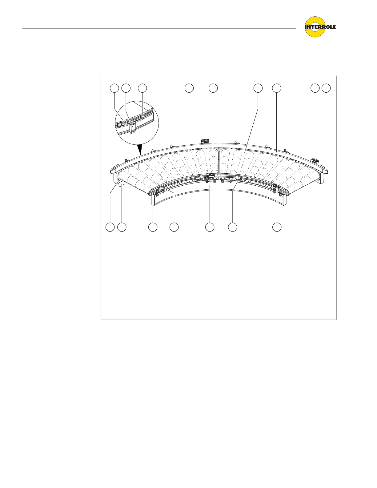
24 V Belt Conveyor Curve BM 8360
Components
7814 1 2 5 643
912 813 711 10
24 V belt conveyor curve BM 8360
1 Conical carrying idler 8 Universal support
2 Conical drive roller 9 Side cover
3 Belt 10 Side guide support
4 Side guide profile 11 End cap (side frame)
5 Photo cell 12 Control
6 End cap (side guide) 13 Side frame (C-profile)
7 Reflector 14 Mounting bracket

Interroll 24 V belt conveyor straight / curve
BM 8350 / BM 8360
Product identification
Version 1.1 (02/2016) en-US
Translation of original instruction manual
15
Property The 24 V belt conveyor curve is a belt curve that is divided into zones and operates with zero
pressure accumulation; its drive is based on the 24 V RollerDrive. It is possible to transport and
store small products, as well as products not suitable for roller tracks.
The 24 V belt conveyor curve is suitable for transporting products up to 20 kg – including
products with uneven or soft bottom.
A closed conveyor belt is pulled over conical carrying idlers and a conical drive roller
(RollerDrive) at the start of every zone. The last roller of each zone serves as tensioning roller.
The conveyor belt can operate with low belt tensioning since the routing is not implemented
using a spherical idler pulley, but by a taper strip affixed to the inside of the belt.
The RollerDrive is connected to a control card that generates the conveying logic or receives
signals from a master controller (PLC).

Interroll 24 V belt conveyor straight / curve
BM 8350 / BM 8360
Product identification
16 Version 1.1 (02/2016) en-US
Translation of original instruction manual
Technical data Belt Curve Light BM 8360
Max. load capacity per zone 20 kg
Conveying speed Max. 0.5 m/s
Ambient temperature +5 to +40 °C
Slider bed Rollers, Interroll Series 1700
Diameter of drive roller 50 mm, tapered bushings
Roller material Steel 1.5 mm, zinc-plated
Number of zones (N) 1 at 45°
2 at 90°
Rated voltage 24 V
Motor type Interroll RollerDrive EC310
Conveyor belt Polyester with PVC coating
Control variants MultiControl
Incline/decline Not suitable
Side profile 115 x 35 mm, without side guide
Between frames 300 to 840 mm
Curve angle 45°, 90°
Inside radius 825 mm
Noise level Leq ≤ 70 dB(A)

Interroll 24 V belt conveyor straight / curve
BM 8350 / BM 8360
Product identification
Version 1.1 (02/2016) en-US
Translation of original instruction manual
17
Scope of supply
The 24 V belt conveyor is completely assembled and wired in its delivery state. The scope of
supply includes:
• Rack, including side frames, cross ties, side covers
• RollerDrive
• Carrying idlers
• Belt
• Closing clips
• Power supply cable
• Control
• Photo cell and reflector (1 each per zone)
• Side guide profiles, side guide support and universal supports
The side guide profiles can optionally be delivered assembled or unassembled.
The scope of delivery does not include:
• Supports
• End caps
• Bus (communication) cables

Interroll 24 V belt conveyor straight / curve
BM 8350 / BM 8360
Product identification
18 Version 1.1 (02/2016) en-US
Translation of original instruction manual
Nameplate
8
3
1
2
4
5
6
7
Nameplate (with arrow in transport direction)
1 Arrow in transport direction 5 Year of construction
2 Type designation 6 Company address
3 Machine no. 7 Weight in kg
4 Layout item no. 8 Level
The information on the nameplate is used to identify the conveyor. The type designation is
required to use the conveyor according to its intended use.
The nameplate is located at the end of the conveyor in the right side frame in transport direction.

Interroll 24 V belt conveyor straight / curve
BM 8350 / BM 8360
Version 1.1 (02/2016) en-US
Translation of original instruction manual
19
Transport and storage
Transport
WARNING
Risk of injury during transport
4Fix the module securely and slip-proof for the transport.
4Ensure that the lifting device (crane, fork lift, etc.) is rated for the weight of the module.
4Ensure that no persons are located under the suspended load while lifting and moving the
module.
Additional information about the transport are located on an information sheet that
accompanies the motor.
4Data about weight and requirements for loading capacity and lifting tackle are located on
the information sheet.
4Remove any persons from the danger zone.
4Wear safety shoes.
4Check the correct fastening for the transport.
The load lifting points are marked on the packet. Individual modules must be gripped at the
bottom profile edge at the ends. Gripping at the top edge is not allowed since it can lead to
inaccuracies of the sensor.
Identification of load
lifting points
After the delivery 4Inspect module for transport damages.
4Immediately notify the carrier and manufacturer in case of damages to avoid losing any
claims for compensation.

Interroll 24 V belt conveyor straight / curve
BM 8350 / BM 8360
Transport and storage
20 Version 1.1 (02/2016) en-US
Translation of original instruction manual
Storage
WARNING
Risk of injury due to improper storage
4Do not stack modules. Do not place any other objects on the module.
4Check module for stability.
4If the module is not immediately placed in operation, store it at a location protected against
humidity and dust.
This manual suits for next models
1
Table of contents
Popular Toy manuals by other brands

Kinderfeets
Kinderfeets Tiny Glider user manual

Faller
Faller TUNNEL PORTAL 2-TRACK manual

Hasbro
Hasbro Spiderman 3 Bump and Go Spiderman 4 Wheeler 69322... instructions

marklin
marklin 37577 instruction manual

Top Flite
Top Flite Stinson Reliant user manual

Eduard
Eduard He 111 H-6 bomb bay quick start guide


