Intersan Wallgate Thrii User manual
Thrii
Installation
Page 1of 23
All information including dimensions, changes in design and material are subject
to manufacturer’s change without formal notice and without obligation. Intersan
assumes no responsibility for use of superseded or voided information. Verify all
rough-in information before installation. It is the responsibility of the installer to
conform with local and national codes.
Intersan Manufacturing Company
1748 West Fillmore St., Phoenix, AZ 85007
Phone: 800-999-3101 Fax: 602-254-1776
intersanUS.com
THRII-inst-Rev1
by
Installation Instructions for models:
THRII –Solid Surface
THRII –Stainless Steel
IMPORTANT
Read instructions entirely prior to installation.
Prior to hooking up the fixture to the water supply
make sure that all the lines are flushed thoroughly.
All wall anchors should have a pull out strength of
1000 lbs. or more.
Units should always be installed according to local
plumbing and/or electrical codes.

Thrii
Installation
Page 2of 23
All information including dimensions, changes in design and material are subject
to manufacturer’s change without formal notice and without obligation. Intersan
assumes no responsibility for use of superseded or voided information. Verify all
rough-in information before installation. It is the responsibility of the installer to
conform with local and national codes.
Intersan Manufacturing Company
1748 West Fillmore St., Phoenix, AZ 85007
Phone: 800-999-3101 Fax: 602-254-1776
intersanUS.com
THRII-inst-Rev1
by
1. Disclaimer & Copyright notice
Every effort has been made to supply information within this manual which is correct. Wallgate Limited and Intersan Mfg.
will not be liable for any damage or loss that arises if the person installing, operating or maintaining the unit has not read
or not complied with the manual
In any event, and without prejudice to any warranties in Wallgate Limited’s and Intersan’s terms and conditions of sale,
Wallgate Limited’s and Intersan’s liability for all damages and losses (including negligence) shall not in any circumstances
exceed the amount paid by the customer for the unit.
Wallgate and Intersan reserve the right to alter, update or improve its product specification at any time without prior
notice. This manual is specific to the product that it has been supplied with at the date of supply.
Without prejudice to any warranties in Wallgate Limited’s and Intersan’s terms and conditions of sale, any warranty will be
null and void if the equipment is installed or serviced by unqualified personnel.
No part of this publication and the information contained may be reproduced, transmitted, stored in a retrieval system,
used or disclosed wholly or partly without prior written permission from Wallgate Limited.
For full warranty details please see Intersan’s Terms and Conditions.
Please ensure this manual is passed to the end user. The manual forms an integral part of the product and should be kept
for its working life. Additional copies of this and other supporting documents are available by contacting Intersan or by
visiting www.intersan.us.
2. Conventions
Certain conventions are used in this manual to make it easier to read and understand. They are shown in the sections
below. It is recommended that you read and understand these warnings before you install and commission the Wallgate
Thrii.
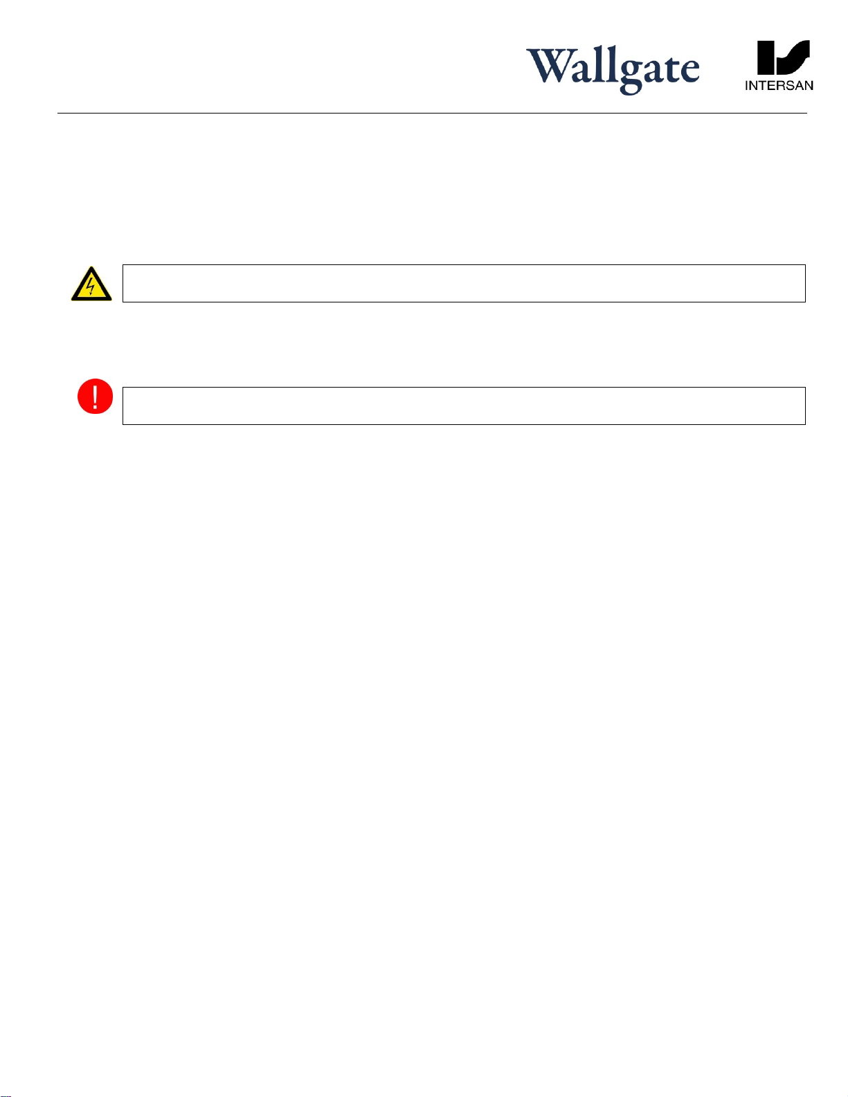
2.1 Warning
A boxed WARNING! is used to give information about hazards associated with electric current and high voltages that can
cause damage, injury or death. Failure to heed these warnings can have serious consequences. Example box:
WARNING! The information contained within this ‘Warning’ box indicates hazards associated with electric
current and high voltages
2.2 Caution
A boxed CAUTION! is used to give information about hazards that can cause damage or injury. Failure to heed these
warnings can have serious consequences. Example box:
CAUTION! The information contained within this ‘Caution’ box indicates hazards that require safety advice for
personnel or potential unit/property damage
2.3 Important
A boxed IMPORTANT: is used to draw your attention to important information on installation, set-up and operation.
Example box:
IMPORTANT: The information contained within this ‘Important’ box gives further useful information.

Thrii
Installation
Page 3of 23
All information including dimensions, changes in design and material are subject
to manufacturer’s change without formal notice and without obligation. Intersan
assumes no responsibility for use of superseded or voided information. Verify all
rough-in information before installation. It is the responsibility of the installer to
conform with local and national codes.
Intersan Manufacturing Company
1748 West Fillmore St., Phoenix, AZ 85007
Phone: 800-999-3101 Fax: 602-254-1776
intersanUS.com
THRII-inst-Rev1
by
2.4 Numbered procedures
Steps in procedures are numbered, starting from 1.
1. This is step 1.
2. This is step 2, etc.
2.5 Bullet lists
A bullet list is used to give information that is not necessarily in sequential order.
2.6 Menu items
Menu items, submenu items and settings, where available, are given in bold.
3. Glossary
The glossary lists all words, abbreviations and technical terminology used in this manual, along with a short description of
these terms.
Term
Description
Thrii®
Hand Wash Unit
Engine Unit
The Engine Unit refers to the complete soap,
water, dryer module mounted on the back of
the fascia.
IR Sensor
The infrared (IR) sensor transmits an invisible
beam into the washbowl area, so that when
interrupted by a person's hand the beam is
rebounded back to the receive sensor. This
creates an electrical signal which rapidly
activates the hand wash cycle.
FNPT
Female National Pipe Thread
Solid Surface
The term Solid Surface refers to the hard
granite-effect or solid color material that is
molded to form the Thrii fascia.
Power up
The external electricity supply is provided to the
Thrii.

Thrii
Installation
Page 4of 23
All information including dimensions, changes in design and material are subject
to manufacturer’s change without formal notice and without obligation. Intersan
assumes no responsibility for use of superseded or voided information. Verify all
rough-in information before installation. It is the responsibility of the installer to
conform with local and national codes.
Intersan Manufacturing Company
1748 West Fillmore St., Phoenix, AZ 85007
Phone: 800-999-3101 Fax: 602-254-1776
intersanUS.com
THRII-inst-Rev1
by
4. Technical Specification
Weight
Item
Fascia
Engine Support
frame, etc. Full
soap container
Total
Solid surface
33.73 lbs.
15.43 lbs.
9.92 lbs.
5.73 lbs.
64.81 lbs.
Stainless Steel
17 lbs.
15.43 lbs.
9.92 lbs
5.73 lbs.
48.06 lbs.
Dimensions
Width
Height
Depth
± 17-3/4”
± 31-1/4”
± 12-1/4”
± 17-3/4”
± 34-1/4”
± 12-1/4”
(9-7/8”behind the panel on all models)
Water Supply
Minimum pressure
Maximum rating
Inlet connection size
Dynamic
14.5 psi / 100 kPa
145 psi / 1000 kPa
½” NPT
Electrical Power requirement
120V AC, 60Hz, 20 Amp
Enclosure IP Rating
IPX4
Regulatory compliance
Complies with:
IAPMO Green Plumbing and
Mechanical Code Supplement
Cal Green
LEED
National Green Building Standard™
Natural Resources Canada R-2000
Standard
Green Building Assessment Protocol
for Commercial Buildings
Solid Surface and Plumbing Code
Compliance
Uniform Plumbing Code (UPC®)
International Plumbing Code (IPC®)
IGC 127-2009
Water heater
Water temperature range
Factory set @ 100°F
*Based on 54°F supply
temperature, 43.5 psi
dynamic pressure & 120V
supply.
86°F to 113°F Flow rate of
0.4 gpm*
Water Resistivity
Water resistivity must not be less than 1300
Ωcm (511.81Ωin) (refer EN603355-2)
Thrii
Installation
Page 5of 23
All information including dimensions, changes in design and material are subject
to manufacturer’s change without formal notice and without obligation. Intersan
assumes no responsibility for use of superseded or voided information. Verify all
rough-in information before installation. It is the responsibility of the installer to
conform with local and national codes.
Intersan Manufacturing Company
1748 West Fillmore St., Phoenix, AZ 85007
Phone: 800-999-3101 Fax: 602-254-1776
intersanUS.com
THRII-inst-Rev1
by
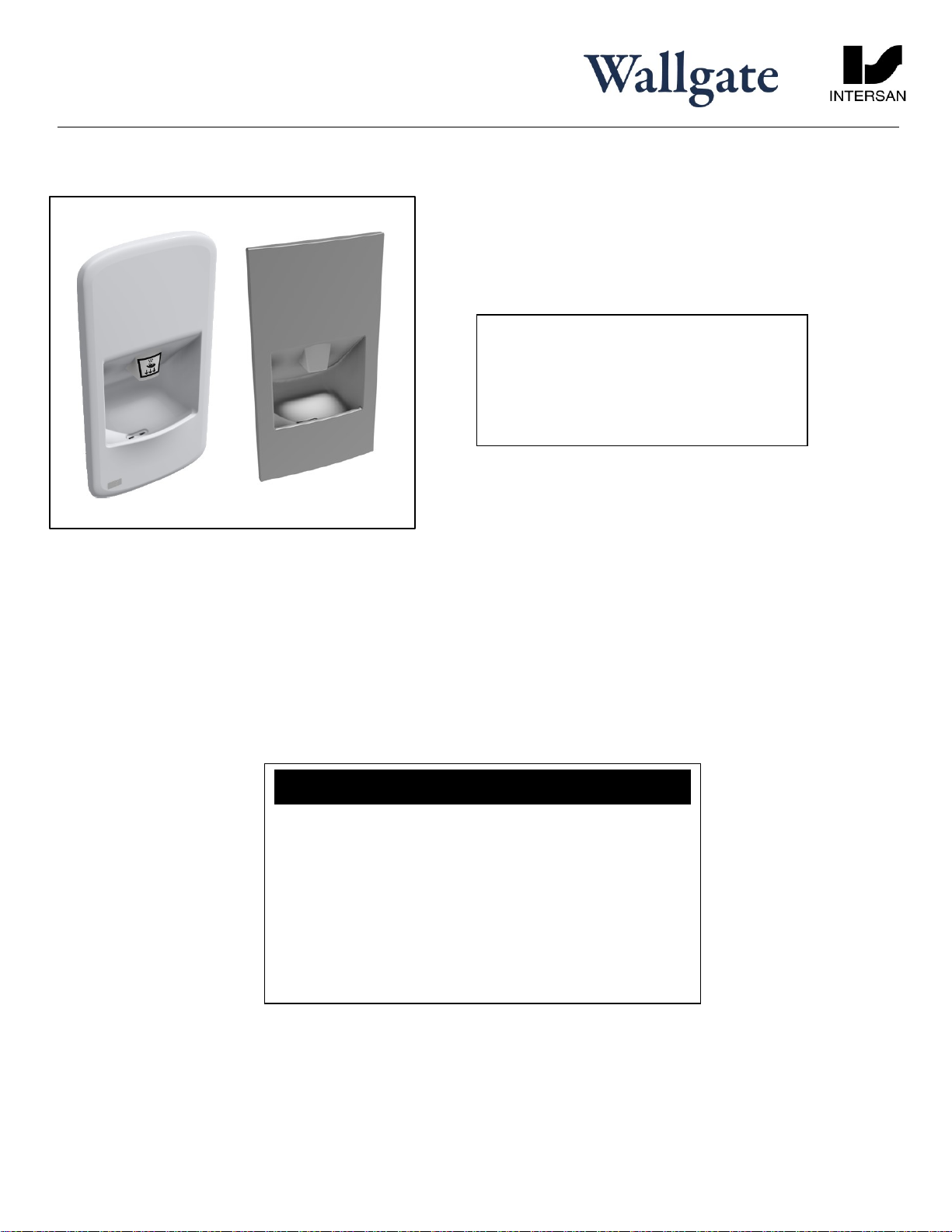
5. Overview
The Thrii is an integrated hand wash dryer unit with automatic infra-red sensor operation. It is available in a
solid surface or stainless steel (grade 304) material.
The unit should only be installed in a frost free environment, to avoid damage.
All models are identical, with the exception of the fascia material & fascia dimensions.
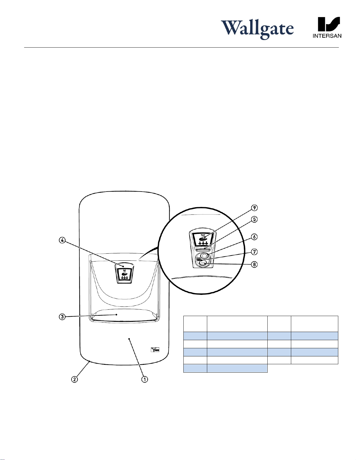
When hands are placed in the center of the wash bowl, an infra-red sensor activates the hand washing and
drying cycle, supplying soap (liquid or foam), warm water and dryer-air in amounts and intervals preset as
required.
The unit can be installed in a variety of wall types, servicing can be carried out either from the front (fascia
unlocks and whole Thrii swings out) or from within an access duct behind the machine.
Item
No.
Description
Item
No.
Description
1
Fascia
6
IR Sensor
2
Fascia Lock (hidden)
7
Soap Outlet
3
Wash Bowl
8
Water Outlet
4
Dispensing Unit
9
Label (optional)
5
Dryer Outlet
Thrii
Installation
Page 6of 23
All information including dimensions, changes in design and material are subject
to manufacturer’s change without formal notice and without obligation. Intersan
assumes no responsibility for use of superseded or voided information. Verify all
rough-in information before installation. It is the responsibility of the installer to
conform with local and national codes.
Intersan Manufacturing Company
1748 West Fillmore St., Phoenix, AZ 85007
Phone: 800-999-3101 Fax: 602-254-1776
intersanUS.com
THRII-inst-Rev1
by
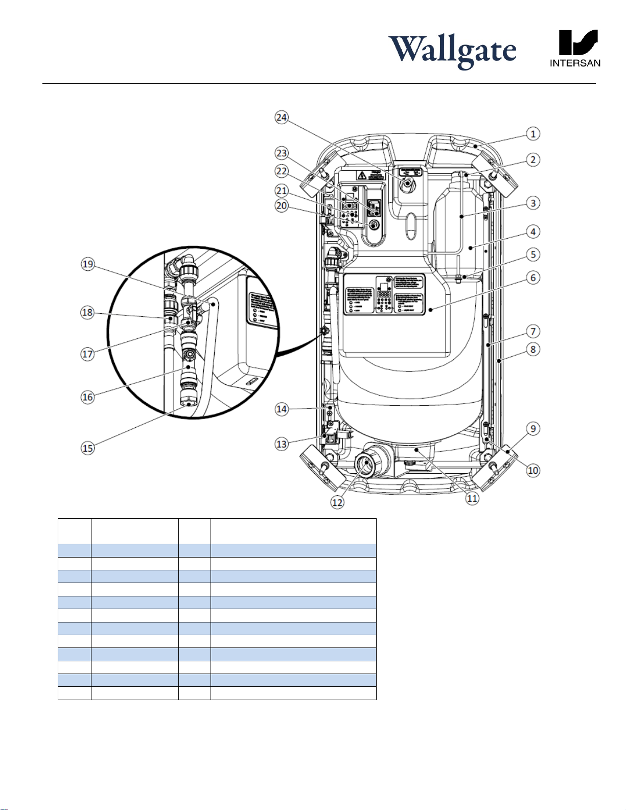
Item
No.
Description
Item
No.
Description
1
Fascia
13
Hinge
2
Container Cap
14
Hinge side lock plate
3
Soap Hose
15
Water (inlet) adapter
4
Soap Container
16
Double Check Valve
5
Container Holder
17
Isolation Tap
6
Engine Cover
18
Water Connection (frame)
7
Locking Bar
19
Engine water supply hose
8
Mounting Frame
20
Engine Cover fixing
9
Clamp bracket
21
Control
10
Fascia Lock
22
LCD Control (see fig. 18)
11
Drain
23
Mains Power socket
12
Waste Outlet
24
Soap Selection switch

Thrii
Installation
Page 7of 23
All information including dimensions, changes in design and material are subject
to manufacturer’s change without formal notice and without obligation. Intersan
assumes no responsibility for use of superseded or voided information. Verify all
rough-in information before installation. It is the responsibility of the installer to
conform with local and national codes.
Intersan Manufacturing Company
1748 West Fillmore St., Phoenix, AZ 85007
Phone: 800-999-3101 Fax: 602-254-1776
intersanUS.com
THRII-inst-Rev1
by
6. Installation and Commissioning
The Wallgate Thrii handwash-drier unit is a three-part assembly consisting of a flush support frame and a hinged fascia and
engine assembly. It is necessary to install the mounting frame and prepare the services (electrical, water and waste) prior
to installing the fascia.
It is important that when selecting a mounting position consideration be given to the suitability of the wall
construction, so that it is able to bear the weight of the assembled unit in both the open and closed positions, and able
to withstand the clamping method as shown in Fig.6
6.1 Package Contents
Before you begin the installation, make sure that you have the following items:
1 Support frame
1 Installation instructions
1 Wall frame waste connector
1 Waste pipe 1-1/4” – 1-1/2” adapter pipe
1 Fascia lock key
1 Mains electrical plug and lead (6-1/2 ft. length)
1 User instruction label
1 Set of mounting brackets and fixings
1 Fascia
1 Engine
1 Container of liquid soap (2/3 gal.)
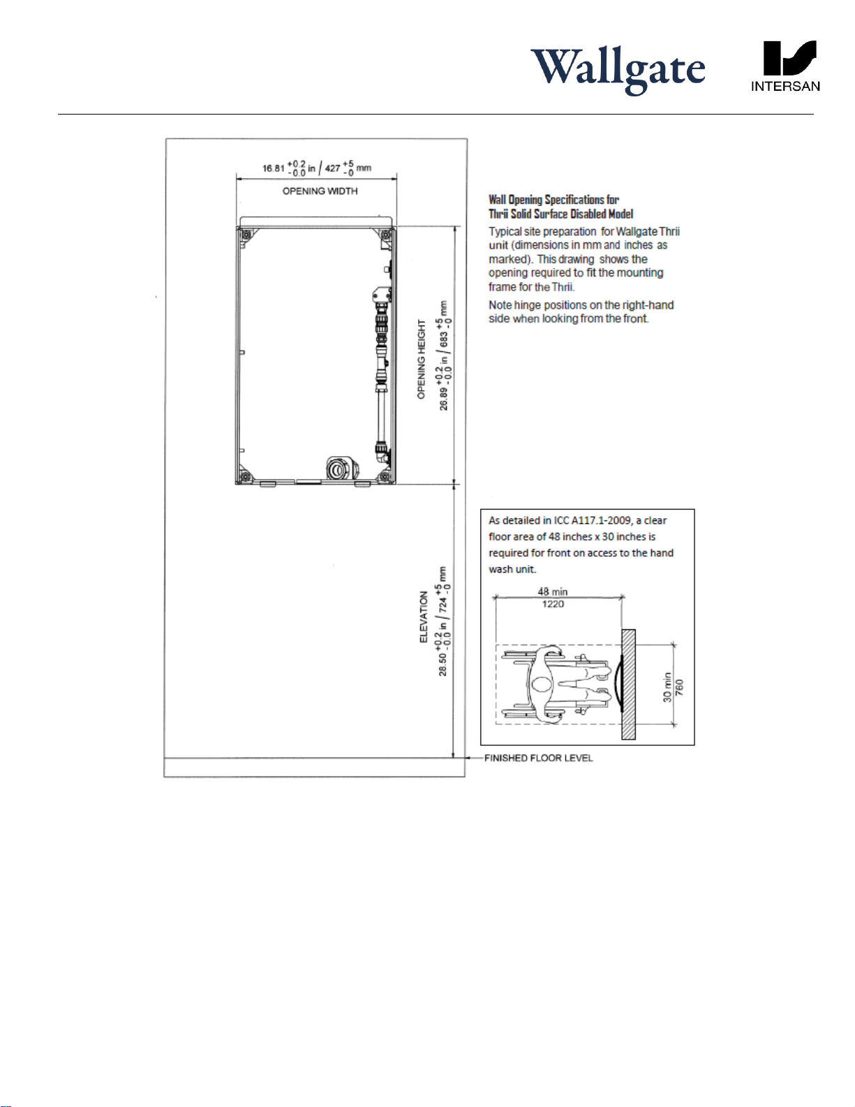
6.2 Site Preparation
6.2.1 Installation guidelines
Looking at the front of the unit the fascia hinges are on the right-hand side. For front access allow for the left-hand
edge of fascia to swing out (120°) to allow full internal access. Water, power and waste water connections are
located on the hinged side of the unit.
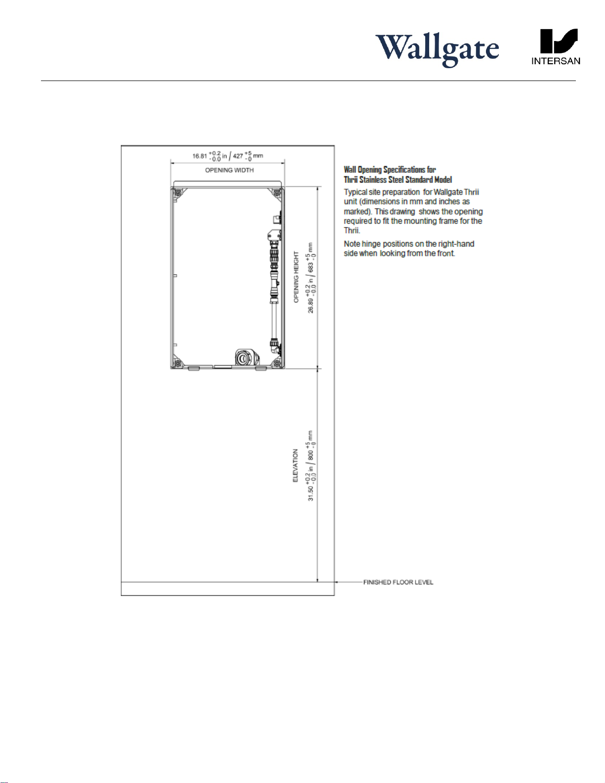
Make an opening in the wall surface according to the dimensions shown in drawing Fig.4 noting the appropriate
mounting height as detailed on the drawing table A.
The opening must be according to the dimensions given in fig.4. The aperture must be accurate in order for the
door mechanism to work effectively. The unit will be fitted to the support frame supplied. The frame is fixed to the
sides of the wall opening using the frame fixing brackets provided. The front edge of the frame must be flush with
the finished face of the wall. On IPS panel walls such as trespa or corian the aperture in the panel should be lined
on the rear face with 50mm timber studding.
Complete all surface finishes such as screed, plaster or tiling before attaching the fascia to the support frame.
All electrical work must be carried out by a qualified electrician and should be installed in accordance with the
current Nationally Approved Regulation
Thrii
Installation
Page 8of 23
All information including dimensions, changes in design and material are subject
to manufacturer’s change without formal notice and without obligation. Intersan
assumes no responsibility for use of superseded or voided information. Verify all
rough-in information before installation. It is the responsibility of the installer to
conform with local and national codes.
Intersan Manufacturing Company
1748 West Fillmore St., Phoenix, AZ 85007
Phone: 800-999-3101 Fax: 602-254-1776
intersanUS.com
THRII-inst-Rev1
by
The installer must:
Provide a 120V 50/60Hz single-phase circuit equipped with a 20 Amp circuit breaker. Locate an outlet in close
proximity to the intended location of the Thrii unit. The Thrii unit is equipped with a 6.5 feet long electrical cord.
A GFCI equipped circuit is recommended, and likely required by your applicable regulations. If so, ensure that a
GFCI is present on the circuit that meets your locally applicable electrical/building/plumbing codes.
The circuit must be equipped with a circuit breaker that is accessible without requiring the fascia of the Thrii unit to
be opened first. Be sure to turn off the circuit breaker before working on or installing the Thrii unit.
Provide a cold water supply mounted behind the wall below the ‘hinge’ side of the aperture. Terminate the cold
water supply with a suitable isolating tap. For optimum operation a dynamic water flow pressure of between 14.5
psi and 43.5 psi is required.
If you are planning on connecting your Thrii unit(s) to a gravity-fed water supply, please contact Intersan in advance
for advice and guidance.
Provide a waste pipe with a 1-1/4” or a 1-1/2” connection and suitable deep seal waste trap behind the wall,
below the ‘hinge’ side of the aperture.
6.3 Installing the support frame, water and waste connections and electric
1. Remove the support frame from the packing box.
2. Orientate the frame with hinge plates on the right-hand side and waste outlet parts at bottom and facing away
from you. The frame front edge should now be facing towards you.
3. Place the frame into the front of the aperture, ensuring it is flush fitting with the finished face of the wall, at the
correct height and perfectly level in the horizontal and vertical planes. The hinge-side of the frame should be hard
up against the aperture.
Thrii
Installation
Page 9of 23
All information including dimensions, changes in design and material are subject
to manufacturer’s change without formal notice and without obligation. Intersan
assumes no responsibility for use of superseded or voided information. Verify all
rough-in information before installation. It is the responsibility of the installer to
conform with local and national codes.
Intersan Manufacturing Company
1748 West Fillmore St., Phoenix, AZ 85007
Phone: 800-999-3101 Fax: 602-254-1776
intersanUS.com
THRII-inst-Rev1
by
Thrii
Installation
Page 10 of 23
All information including dimensions, changes in design and material are subject
to manufacturer’s change without formal notice and without obligation. Intersan
assumes no responsibility for use of superseded or voided information. Verify all
rough-in information before installation. It is the responsibility of the installer to
conform with local and national codes.
Intersan Manufacturing Company
1748 West Fillmore St., Phoenix, AZ 85007
Phone: 800-999-3101 Fax: 602-254-1776
intersanUS.com
THRII-inst-Rev1
by

Thrii
Installation
Page 11 of 23
All information including dimensions, changes in design and material are subject
to manufacturer’s change without formal notice and without obligation. Intersan
assumes no responsibility for use of superseded or voided information. Verify all
rough-in information before installation. It is the responsibility of the installer to
conform with local and national codes.
Intersan Manufacturing Company
1748 West Fillmore St., Phoenix, AZ 85007
Phone: 800-999-3101 Fax: 602-254-1776
intersanUS.com
THRII-inst-Rev1
by
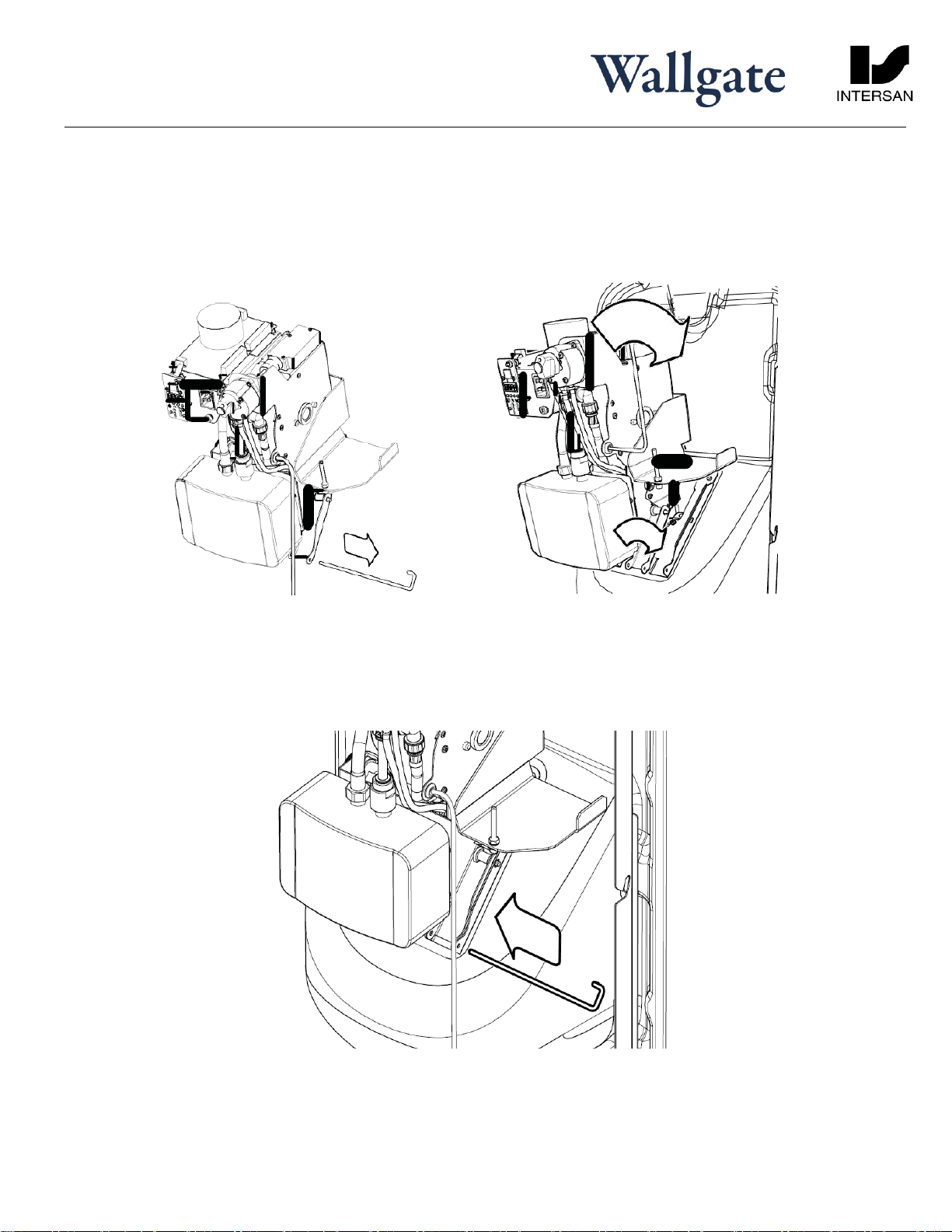
Solid Surface Model Stainless Steel Model
Typical site installation of Thrii unit
showing clamping bracket (view on rear)

Thrii
Installation
Page 12 of 23
All information including dimensions, changes in design and material are subject
to manufacturer’s change without formal notice and without obligation. Intersan
assumes no responsibility for use of superseded or voided information. Verify all
rough-in information before installation. It is the responsibility of the installer to
conform with local and national codes.
Intersan Manufacturing Company
1748 West Fillmore St., Phoenix, AZ 85007
Phone: 800-999-3101 Fax: 602-254-1776
intersanUS.com
THRII-inst-Rev1
by
4. Insert the 4 No. M10 x 150mm (6”) threaded rods through the corner angles on the support frame and into the
brackets as shown in figure above.
5. Tighten all four (4) brackets until the wall frame is held securely in place in the wall opening. It is important that
the frame side members are not distorted when tightening to the wall, as this may prevent the hinge and catch
mechanisms from working properly.
6. Once the frame is securely attached to the wall, if necessary make good any excessive gaps between the frame
and the wall that may not be covered by the fascia.
7. Install the waste connector to the frame as shown in figure below along with the pipe adapter which then is
terminated to the deep seal waste trap as detailed in section 6.2 site preparation.
8. Provide a cold water supply pipe to connect to the inlet connector on the support frame. Note that the water
inlet connector is ½” copper fitting on the main water supply.
If pipe sealing compound is used, avoid applying excessive amounts as particles of sealant can block water
filters and impede valve operation.
Before carrying out the following steps, flush the main water supply pipes to remove any debris and trapped
air. Failure to do so may result in damage and failure of the unit.
9. Connect the deep seal waste trap to the outlet fitting on the support frame.
10. Connect the supplied electrical cable to a 20 amp circuit equipped with an accessible circuit breaker and GFC�if
required per locally applicable code requirements.
6.4 Mounting the fascia
Ensure that the fascia is fully supported until both hinges are fully engaged. Failure to do so may damage the
hinges
For ease of installation it is recommended to have at least two people carry out this operation
Ø1-1/4”
Thrii
Installation
Page 13 of 23
All information including dimensions, changes in design and material are subject
to manufacturer’s change without formal notice and without obligation. Intersan
assumes no responsibility for use of superseded or voided information. Verify all
rough-in information before installation. It is the responsibility of the installer to
conform with local and national codes.
Intersan Manufacturing Company
1748 West Fillmore St., Phoenix, AZ 85007
Phone: 800-999-3101 Fax: 602-254-1776
intersanUS.com
THRII-inst-Rev1
by
1. Remove the fascia from the packing box.
2. With one person holding the fascia, the second person should extend the hinge components on the right side of the
fascia so they are fully extended. Position the fascia assembly so the two hinges are suspended next to the hinge side
lock plates mounted on the support frame.
Have one person hold the fascia so it is suspended where the hinge halves on the fascia are in alignment with the
halves attached to the mounting frame, hook each of the hinges on the fascia side around the corresponding bar each
hinge on the mounting frame side, and latch each hinge. CONTINUE SUPPORTING THE FASCIA UNTIL YOU HAVE
VERIFIED THAT THE HINGES ARE ATTACHED AND SECURE.
Continue supporting the weight of the fascia, and test the ability of the fascia to swing freely on the hinges. If any
binding or limitation in the range of motion occurs, check each of the two hinges to ensure they are fully attached and
secure (see figure below).
3. Engage the ‘Hinge release lock’ spigot, fitted to each hinge to prevent accidental hinge latch release.
Thrii
Installation
Page 14 of 23
All information including dimensions, changes in design and material are subject
to manufacturer’s change without formal notice and without obligation. Intersan
assumes no responsibility for use of superseded or voided information. Verify all
rough-in information before installation. It is the responsibility of the installer to
conform with local and national codes.
Intersan Manufacturing Company
1748 West Fillmore St., Phoenix, AZ 85007
Phone: 800-999-3101 Fax: 602-254-1776
intersanUS.com
THRII-inst-Rev1
by
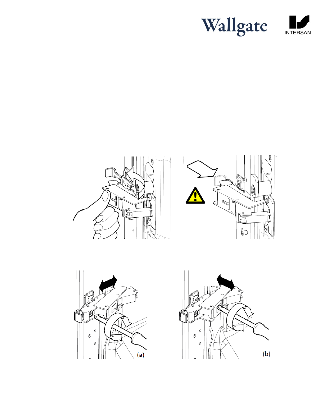
4. It is necessary to check the fascia alignment with the frame before proceeding further, as the hinges may need
adjustment. Carefully close the fascia ensuring the door opens and closes freely. In the closed position, visually check
the gap between the fascia and the wall along the hinged edge, and adjust the hinges as appropriate to ensure an
even fit using the adjustment screw on the hinges see figure below. Do not over-tighten as this may result in the fascia
damaging the wall finish. Horizontal adjustment of the fascia door can be configured.
5. Once the fit has been checked, close the fascia fully to check the locking bar operation. The locking bar is spring-
loaded and may require a firm push to engage correctly. To re-open insert the key provided into the fascia lock release
at the base of the fascia, ¼ turn anti-clockwise and push the key up to disengage the lock and allow the fascia to open
freely.
6. For installations where front access is not required in addition to the hinge release lock, engage the 2 hinge side locks,
rotating into the slot provided in the frame as shown in figure below and when the lock bar has been fully engaged,
relocate the top screw fixing into the locking position below, as shown in figure below.
Thrii
Installation
Page 15 of 23
All information including dimensions, changes in design and material are subject
to manufacturer’s change without formal notice and without obligation. Intersan
assumes no responsibility for use of superseded or voided information. Verify all
rough-in information before installation. It is the responsibility of the installer to
conform with local and national codes.
Intersan Manufacturing Company
1748 West Fillmore St., Phoenix, AZ 85007
Phone: 800-999-3101 Fax: 602-254-1776
intersanUS.com
THRII-inst-Rev1
by
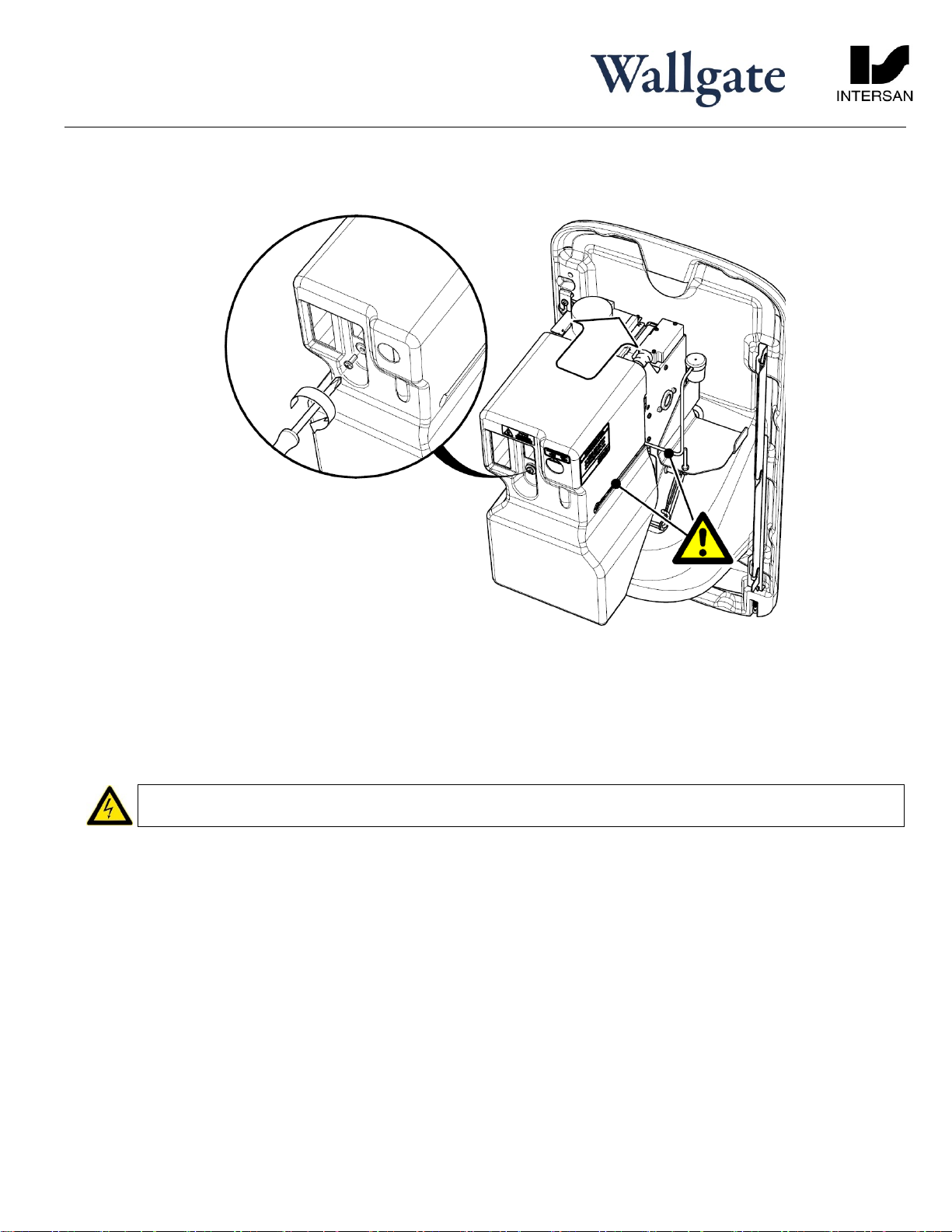
6.5 Engine installation
1. Remove the engine cover, retaining the engine cover fixing.
2. Remove the securing pin out through the side from the base of the engine.
3. Present the engine to the engine mounting plate on the back of the fascia locating the dispensing nozzle into the
aperture provided. Align the engine on the plate and click into place.
4. Replace the securing pin through both mounting plates and engine ensuring it passes fully through this assembly.
Thrii
Installation
Page 16 of 23
All information including dimensions, changes in design and material are subject
to manufacturer’s change without formal notice and without obligation. Intersan
assumes no responsibility for use of superseded or voided information. Verify all
rough-in information before installation. It is the responsibility of the installer to
conform with local and national codes.
Intersan Manufacturing Company
1748 West Fillmore St., Phoenix, AZ 85007
Phone: 800-999-3101 Fax: 602-254-1776
intersanUS.com
THRII-inst-Rev1
by
5. Replace the engine cover, ensuring the flexible hose and soap hose attached does not foul upon reassembly, and
secure the cover into place with the fixing provided.
6.6 Electrical and Water Connections
From the rear side of the wall:
6.6.1 Electrical connection from the wall mounted fused spur switch to the Thrii:
All electrical work must be carried out by a qualified electrician and should be installed in accordance with the
current national, regional and local regulations.
GFCI protection is likely required, and should be installed in an appropriate manner per applicable electrical, plumbing
or building codes.
Complete the electrical connection by fitting the plug into the socket on the rear of the engine. Ensure the cable is a
suitable length so that the door can fully open without catching or fouling.
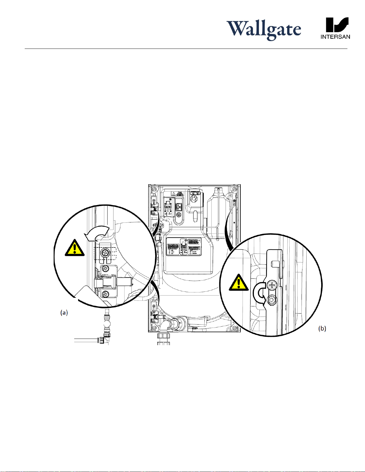
6.6.2 Mains water connection from support frame to the engine:
Using the flexible water hose provided take the loose end of the hose, which is attached to the engine, and attach it to
the water inlet connection mounted on the upper bracket part of the support frame (see figure below). With all
services connected to the Thrii, open and close the fascia assembly to ensure that the wiring and piping feeds move
without snagging or kinking. Ensure the waste spigot from the wash bowl smoothly engages with waste outlet on the
frame bracket.

Thrii
Installation
Page 17 of 23
All information including dimensions, changes in design and material are subject
to manufacturer’s change without formal notice and without obligation. Intersan
assumes no responsibility for use of superseded or voided information. Verify all
rough-in information before installation. It is the responsibility of the installer to
conform with local and national codes.
Intersan Manufacturing Company
1748 West Fillmore St., Phoenix, AZ 85007
Phone: 800-999-3101 Fax: 602-254-1776
intersanUS.com
THRII-inst-Rev1
by
6.7 Commissioning for use
To commission the Wallgate Thrii:
1. Ensure the engine cover is securely fitted and the electrical plug is fully pushed in.
2. Fully open the water supply valve to the unit. Check the system for external leaks. If no leaks, open the water valve on
the support frame.
3. Close the fascia, ensuring it closes fully against the wall. Adjust the hinges if required and push the fascia to the closed
position ensuring the locking bar engages fully.
The unit should only be operated with the fascia in the fully closed position and the waste outlet engaged.
Failure to do so may result in leakage.
4. Switch ON the circuit breaker to power up the circuit, which will turn on the Thrii, making the unit ready for use.
½” NPT
Cold water supply
Thrii
Installation
Page 18 of 23
All information including dimensions, changes in design and material are subject
to manufacturer’s change without formal notice and without obligation. Intersan
assumes no responsibility for use of superseded or voided information. Verify all
rough-in information before installation. It is the responsibility of the installer to
conform with local and national codes.
Intersan Manufacturing Company
1748 West Fillmore St., Phoenix, AZ 85007
Phone: 800-999-3101 Fax: 602-254-1776
intersanUS.com
THRII-inst-Rev1
by
5. Upon initial power-up the Thrii automatically runs through a 15 second water calibration cycle. This is repeated every
time the mains power supply is interrupted. This will also activate the clock on the LCD.
6. Reopen the fascia using the key provided.
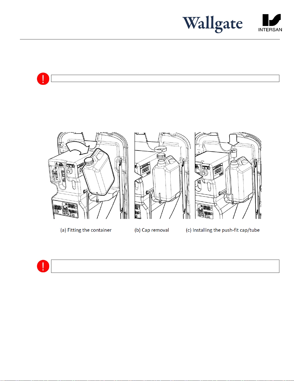
Important! A range of compatible liquid soaps & specifications are available from Intersan.
7. To install the soap container, place the soap container into its stowage position, to the right of the engine unit (figure
a), ensuring the cap is outer most.
8. Unscrew the cap from the soap container (figure b)and replace with the push-fit cap pre-connected to the soap tube
(figure c) pushing fully into place ensuring no leaks.
9. Press the soap prime switch, (located at the rear of the engine unit in the window aperture to the left of the mains
connector, until soap is consistently dispensed into the bowl.
If only rear access is required lock the fascia into the closed position using the front screw fixing and secure
using the fixings provided.
10. When ready for use, a green light will emit from the dispensing unit into the wash bowl. Once hands are placed under
the dispensing unit this light will turn to blue and will activate the wash cycle. The light then changes to red when the
hand dryer is operating.
Check the wash & dry cycles operates correctly as per the list of checks below and repeat the cycle at least five times.
Soap dispenses
Water dispenses & water is warm (Note that water dispenses whilst hand sensor detects the presence of hands in
the bowl, the water will stop when the sensor fails to detect any hands after a period of 2 seconds.
Hand dryer operates (Note that the dryer operates whilst the hand sensor detects the presence of hands in the
bowl, the dryer will stop when the sensor fails to detect any hands after a period of 2 seconds.
Thrii
Installation
Page 19 of 23
All information including dimensions, changes in design and material are subject
to manufacturer’s change without formal notice and without obligation. Intersan
assumes no responsibility for use of superseded or voided information. Verify all
rough-in information before installation. It is the responsibility of the installer to
conform with local and national codes.
Intersan Manufacturing Company
1748 West Fillmore St., Phoenix, AZ 85007
Phone: 800-999-3101 Fax: 602-254-1776
intersanUS.com
THRII-inst-Rev1
by
11. If required by the customer, fit the user instruction label to the dispensing unit.
12.Upon completion ensure that a copy of the instruction manual (or leaflet), the instruction label and the fascia lock key
are passed to the customer.
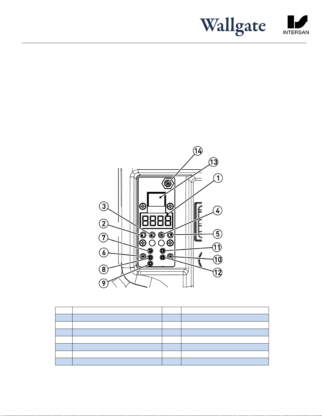
7. Program settings
The Wallgate Thrii operational program is supplied factory set but can be adjusted to suit the end user requirements
Any service or repair work must be done by a qualified engineer. During the warranty period, the service or repair must
only be done by a Wallgate engineer or appointed service agent. Refer to the Wallgate terms and conditions for warranty
information.
Item
Description
Item
Description
1
LCD
8
MED Fan speed LED indicator
2
Menu Select button
9
LOW Fan speed LED indicator
3
UP Button
10
SOAP Select button
4
DOWN Button
11
LIQUID LED indicator
5
ENTER Button
12
FOAM LED indicator
6
FAN SPEED Button
13
Ribbon cable connector
7
HIGH Fan speed LED indicator
14
Soap prime switch
Thrii
Installation
Page 20 of 23
All information including dimensions, changes in design and material are subject
to manufacturer’s change without formal notice and without obligation. Intersan
assumes no responsibility for use of superseded or voided information. Verify all
rough-in information before installation. It is the responsibility of the installer to
conform with local and national codes.
Intersan Manufacturing Company
1748 West Fillmore St., Phoenix, AZ 85007
Phone: 800-999-3101 Fax: 602-254-1776
intersanUS.com
THRII-inst-Rev1
by
7.1 Operation
The hand wash and dry cycle is activated when your hands are placed centrally into the wash bowl below the dispensing
nozzles. An infra-red sensor initiates the cycle when it detects hands in the bowl area. When the cycle starts, a sequence of
soap, warm water and hand dryer air are dispensed. Note that the hand dryer is programmed to cease operation shortly
after hands have been removed from the wash bowl, or when the pre-set dryer cycle time has been reached.
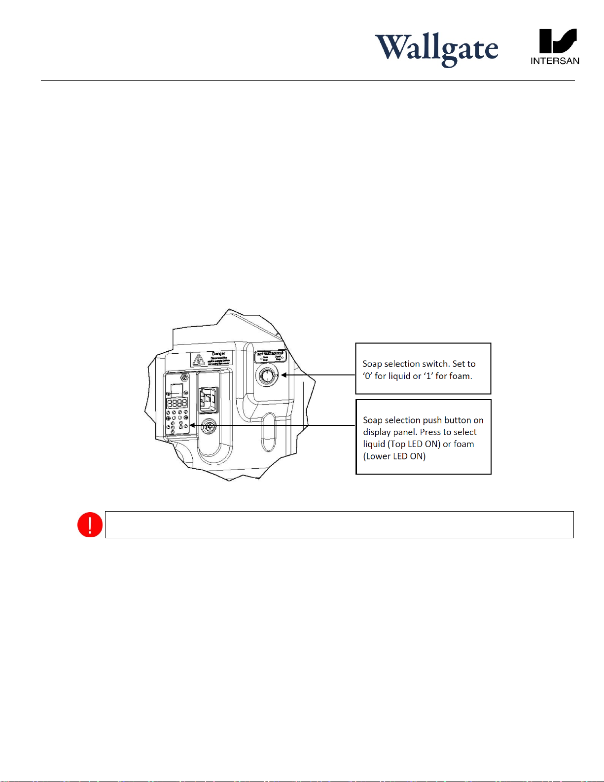
7.1.1 Soap Operation
There are 2 settings for soap delivery, LIQUID (default) or FOAM. The controls to set the required soap option are located
on engine unit. To change the settings the unit must be powered up. There are 2 controls that need to be altered:
1. At the window to the left of the mains connector there is a small push button labelled ‘Soap’. Press and hold this
button to select the desired setting this will be confirmed by an illuminated LED.
2. Adjust the soap selection switch to position 1.
Ensure that both button setting and soap selection knob position select the same operation. Failure to do so
may result in an incorrect operation.
Low soap level indicator:
A function on the unit can be enabled, to indicate that the soap container level is low. When this function is set to ON
(Default setting is OFF) and the soap is at a low level the bowl light will pulse once per second. To turn ON this
function refer to section 7.2 for “Advanced Adjustments” and select menu item F146 which is the setting for number
of soap operations before the warning light is activated. Setting this to 20 will activate the warning light after 2000
operations. The setting may require adjustment if the number of operations per full soap container is found to be
fewer or greater than the setting.
To reset the warning light there are two options.
a. Press buttons 2 & 3 on the display together & hold for 5 seconds.
Table of contents
Popular Washer manuals by other brands

Electrolux
Electrolux EWF 12570 X user manual

Koenic
Koenic KWM 71412 A3 user manual

LG
LG F1612SBS owner's manual

Electrolux
Electrolux EW 806 F Installation and instruction manual

GE
GE PTW900BPTRS Owner's Manual & Installation Instructions

HENNESSY INDUSTRIES
HENNESSY INDUSTRIES AMMCO 1475 Safety Instructions, Setup Instructions, Operating Instructions, Maintenance Instructions with Parts


Hotpoint Ariston
Hotpoint Ariston ARSF 109 Instructions for use

Zanussi Electrolux
Zanussi Electrolux ZWA 5120 instruction manual

Hobart
Hobart UCX Installation and operation instruction

Indesit
Indesit SIXL125SEU Service information manual

Rhima
Rhima RF450 Operator's manual

arcelik
arcelik 9100 PMG user manual