Interscan Corporation HALIMETER PLUS User manual

120-00011 Rev. New
HalimeterPLUS User Manual 7/15/2020
I
Interscan Corporation.
User Manual
HALIMETER
PLUS
P.N. 120-00011

120-00011 Rev. New
HalimeterPLUS User Manual 7/15/2020
II
Table of Contents
Section 1 - Introduction.................................................................1
1.1 Precautions ...............................................................1
1.2 HALIMETER
PLUS Packing Contents....................2
Section 2 –Instrument Description ...............................................3
2.1 Controls & Features...................................................3
2.2 Sample Inlet Tubing and Coupling Connector...........5
2.3 Sample Straw...........................................................6
2.4 Analog Output Connections......................................7
Section 3 –HalimeterPLUS Operation ......................................8
3.1 Powering The Halimeter
PLUS................................8
3.2 Main Menu Navigation...............................................8
3.3 Measure Mode ..........................................................9
3.5 Charging The Batteries............................................11
3.6 Setup Menu.............................................................12
Section 4 –Breath Sampling Considerations..............................13
4.1 Sample Interferences ..............................................14
4.2 Proper Sampling Technique .....................................14
Section 5 –Taking Breath Samples............................................16
5.1 Zeroing The Halimeter
PLUS.................................16
5.2 Taking Samples........................................................17
5.3 Auto Blockage Detection ..........................................18
Section 6 –Data Storage And Access ........................................19
6.1 FILES Menu .............................................................19
6.2 Accessing And Saving Data .....................................20
Section 7 - Calibration.................................................................22
7.1 Calibration Procedure..............................................22
Section 8 –Sensor Replacement Procedure...............................25
8.1 Sensor Removal......................................................25
8.1 Sensor Installation ..................................................27
Section 9 - Troubleshooting........................................................29
Section 10 - Warranty.................................................................30
Section 11 - Customer Service....................................................31
11.1 Return Authorization..............................................31
11.2 Spare Parts ...........................................................31

120-00011 Rev. New
HalimeterPLUS User Manual 7/15/2020
1
Section 1 - Introduction
Congratulations on your purchase of the INTERSCAN HalimeterPLUS! The Halimeter®
PLUS is a complete reimagining of the world’s most trusted and widely used instrument
for the analysis and treatment of chronic halitosis.
Your instrument combines field-proven electrochemical sensing technology with an all-
new electronics package, intuitive controls, and a real-time graphics display. Key features
include:
•Real time continuous sampling and monitoring.
•Automatic data logging downloadable in a .csv (commas separated value) file.
•SD Card data storage.
•User adjustable flow rate with auto blockage detection.
•Rechargeable Li-ion battery providing 5-8 hours of monitoring in the field.
•Instantaneous and accumulated measurement display (Monitor and Graph views).
•Quick connect sampling ports.
•Mini USB charging port.
•Rear panel terminals for analog outputs.
1.1 PRECAUTIONS
Read this manual fully and carefully before using your instrument. This manual should
be read by anyone who will be operatingthe HalimeterPLUS to ensure accurate
measurement and long life.
NOTE 1:It is a good idea to charge the batteries in your instrument before initial
operation. Connect the battery charger and run the instrument for 24 hours in OFF
MODE to allow the batteries to fully charge and the sensor to fully stabilize. See
section 3 for details on battery charging and navigating operation modes.
NOTE 2: It is recommended that the HalimeterPLUS be connected to the power
supply/battery charger during long term storage. See section 3.5 for battery
charging information.

120-00011 Rev. New
HalimeterPLUS User Manual 7/15/2020
2
WARNING: ALCOHOL OR CHLORINATED MOUTHWASH RESIDUE REMAINING
IN THE MOUTH OF A SAMPLE SUBJECT WILL RESULT IN ERRONEOUS
HALIMETERPLUS READINGS AND SERIOUSLY LIMIT SENSOR LIFE. IF
MOUTHWASH HAS BEEN USED PRIOR TO TAKING A HALIMETERPLUS
READING, RINSE OUT THE MOUTH THOROUGHLY WITH WATER AT LEAST 30
MINUTES PRIOR TO SAMPLING.
IT IS ALSO RECOMMENDED THAT THE PATIENT SHOULD REFRAIN FROM
EATING, SMOKING, DRINKING (WATER IS ALLOWED) AND ORAL HYGIENE
ACTIVITIES FOR 3-4 HOURS BEFORE TESTING.
THE SENSOR WARRANTY WILL BE VOIDED IF THE SENSOR IS
CONTAMINATED BY MOUTHWASH VAPOR OR THAT OF OTHER
CONTAIMNANT LIQUIDS.
Carefully remove the HalimeterPLUS from it’s packing container along with the
accessories. Inspect the instrument for any damage. Check that all accessories are
included according to the contents list shown below:
HalimeterPLUS
Mini USB Wall Charger/Charging Cable
Sample Tubing / tube connector
Sample Straws (10 ea.)
HalimeterPLUS User Manual
Contact the Interscan Service Dept. immediately (see section 11) to report any
damaged or missing items.
Any items reported damaged or missing after 30 days from delivery will not be
covered by INTERSCAN and the customer will be responsible for any
replacement or repair expense.
1.2 HALIMETERPLUS PACKING CONTENTS

120-00011 Rev. New
HalimeterPLUS User Manual 7/15/2020
3
Section 2 – Instrument Description
Figure 1 below shows the HalimeterPLUS case and front panel features which are
described in the table and sections that follow.
LDC DISPLAY –Displays all relevant
numeric and text information related to
sampling and menu navigation. Breath
sample values can be displayed
numerically or graphically. See section
2.1.1 for display details.
IN FITTING –Quick connect socket for
introduction of sample via sample inlet
tubing. See section 2.2 for connection
details.
OUT FITTING –Exhaust port for sample
stream. No connection is necessary. DO
NOT BLOCK THIS PORT!
MINI USB PORT –USB connector for
battery charging and powered operation.
See section 3.5
TILT-BACK FEET –Provides a slight tilt
angle for table-top use. Feet are shipped
in the collapsed or “flat use” position but
can be engaged by simply rotating them
forward until they lock in place.
SD CARD –Slot for data storage memory
card. See section 6 for details on data
storage and accessing data.
CONTROL KEYPAD –Button cluster for
unit operation. See section 2.1.2 for
control details.
2.1 CONTROLS & FEATURES
CARRY HANDLE
TILT BACK FEET
IN FITTING
LCD DISPLAY
SD CARD
MINI USB PORT
CONTROL
KEYPAD
FIGURE 1
OUT FITTING

120-00011 Rev. New
HalimeterPLUS User Manual 7/15/2020
4
CARRY HANDLE –Enables easy carrying of the instrument between sampling
locations. The handle can also be rotated 180° to the underside of instrument case
for deeper angled tilt during table-top use as shown in Figure 2. To rotate handle, pull
out on the handle mount on the left side of case and rotate handle towards the front
of the instrument. It will lock into place when at the 180° position. Be sure to collapse
the tilt back feet before rotating the handle.
FIGURE 2
2.1.1 DISPLAY FIELDS AND INDICATORS
TheHalimeterPLUSdisplayscreenoffersavarietyofinformationasdetailedinFigure
3 below. Elements will be visible depending on the active mode and operation being
performed.
HANDLE MOUNT
MODE STATUS
INDICATOR
OPERATION
STATUS
INDICATOR
OPERATION
TIMER
BATTERY LIFE
REMAINING
PEAK VALUE
INDICATOR
PEAK VALUES
READING VALUE
AVERAGE VALUE
INDICATOR
GAS & UNIT
LABELS
FLOW
RATE
ZERO MODE
INDICATOR
FIGURE 3
DATA SAVE
MODE ACTIVE
INDICATOR

120-00011 Rev. New
HalimeterPLUS User Manual 7/15/2020
5
2.1.2 CONTROL KEYPAD
The HalimeterPLUS control keypad is detailed in Figure 4 below. Each button is
described in the table that follows.
POWER BUTTON –Press to turn power
to instrument ON. Press from the MAIN
MENU to turn power OFF.
ARROW BUTTONS –Used to navigate
through the instrument’s menus and enter
values during numeric and text entry.
Proper use is indicated in specific function
descriptions.
ENTER BUTTON –Used to advance
through the sequential menus and finalize
certain functions.
STOP BUTTON –Used to back up in
sequential menus or end a particular
function.
SAVE BUTTON –Press at any point
during sampling to save current data to
memory card.
The provided sample tubing connects to the
SAMPLE INLET fitting via a “push-in” style tube
adapter shown to the right. To connect, first push
down on the metal locking tab then plug the adapter
into the “IN” connector until you hear the locking
mechanism click into place.
2.2 SAMPLE INLET TUBING AND COUPLING CONNECTOR
POWER BUTTON
ARROW BUTTONS
ENTER BUTTON
STOP BUTTON
SAVE BUTTON
FIGURE 4

120-00011 Rev. New
HalimeterPLUS User Manual 7/15/2020
6
Toremovethetubeadapter,press downonthemetal
locking tab on the top of the connector while pulling
out on the tubing.
The tube coupling connector fitted to the other end of
the sample tubing shown below is provided as an
interface for the sample straw. This connector should
always be left in place.
2.3 SAMPLE STRAW
The Sample Straw is the means of sample delivery for the patient. Your instrument comes
with 10 straws for connection fo the tube coupling connector during sampling.
To connect the straw to the tube coupling connector, simply press the straw in to the
connector port until you feel it hit the tube stop. The straw can easily be removed from the
connector merely by pulling it away from the connector.
NOTE: For proper sanitation, always use a new straw when taking samples from a
new patient. DO NOT RE-USE STRAWS WITH DIFFERENT PATIENTS.
When replacing straws, Interscan recommends the use of the Dixie JW7 which is of the
proper diameter, wall thickness and material makeup for optimal air seal when interfaced
with the coupling connector. Specifications are noted below.
Replacement straw specifications (Dixie JW7 recommended):
- Outside diameter –0.217 in. (5.512 mm)
- Wall thickness –0.007 in. (0.1778 mm)
- Material –Translucent polypropylene

120-00011 Rev. New
HalimeterPLUS User Manual 7/15/2020
7
2.4 ANALOG OUTPUT CONNECTIONS
The HalimeterPLUS is equipped with 0-2.5 V and 4-20 mA output signals available at
the10pin rearpanelterminalblockasshownbelow.Eachsignalrangecorrespondstothe
full scale range of the instrument from 0 - max range.
Connect to the terminal block by inserting wire conductor into the desired terminal and
tightening the terminal’s screw. The terminal block can be removed from the rear panel for
ease of wiring by gently pulling the block away from the panel. Re-connect the block by
gently pressing it back into thereceptacle.
Usethe VCC output(Pin3) asthepositivereferenceforthe 4-20mAoutput(AOUT1–Pin
8)andthedeviceground(Pin1or2)asthenegativereferenceforthe2.5Voutput(AOUT2
–Pin 7).
PIN
NAME
TYPE
DESCRIPTION
1
2
3
4
5
6
7
8
9
10
GND
GND
VCC
-
-
-
AOUT2
AOUT1
-
-
Reference
Reference
Reference
N/C
N/C
N/C
Analog Voltage Output
Analog Current Output
N/C
N/C
Local Device Ground
Local Device Ground
+5 Volts
-
-
-
Breath Measurement in volts
Breath Measurement in milliamps
-
-

120-00011 Rev. New
HalimeterPLUS User Manual 7/15/2020
8
Section 3 – Halimeter PLUS Operation
To turn the instrument on, press the green
power button. The MAIN MENU screen showed
on the right will be displayed.
Check the battery life indicator in the lower right
corner of the display and confirm that adequate
battery liferemains for use. Expectedbattery life
is 5-8 hours on a full charge depending on
nature of use. See section 3.5 for details on charging the batteries.
To power the unit down, navigate to the MAIN
MENU screen shown on the right and press the
green power button. The screen will prompt you
to confirm power down as shown. Press the
RIGHT ARROW button to confirm power down.
NOTE: Normal power down only works from the MAIN MENU screen. Access the main
menu screen from any of the operating modes or sub-menus by successively pressing
the STOP button until the MAIN MENU is displayed.
To navigate through the MAIN MENU, use the UP or DOWN ARROW buttons to highlight
the desired menu selection then use the RIGHT ARROW button to open the highlighted
sub-menu. This is the procedure for navigating any sub-menu in the HalimeterPLUS.
3.1 POWERING THE HALIMETERPLUS
3.2MAIN MENU NAVIGATION

120-00011 Rev. New
HalimeterPLUS User Manual 7/15/2020
9
The MAIN MENU offers 3 sub-menu selections that are detailed below:
MEASURE –Sequential sub-menu of primary operating modes as follows:
- STARUP MODE > OFF MODE > ON MODE > SAMPLE MODE.
See section 3.3 for details on the MEASURE sub-menu.
SETUP –Sub-menu of user adjustable parameters and functions including:
- FLOW RATE
- SAMPLING MODE
- DATE/TIME
- BREATH CALIBRATION
- ECS CALIBRATION
- FACTORY SETTINGS
See section 3.6 for details on the SETUP sub-menu.
FILES –Sub-menu of data storage parameters as follows:
- Create (create and name new data file)
- Delete (delete any existing data file)
- Select (select any existing data file for next sample storage)
- Recent Measurements (list of 10 most recent samples taken)
See section 6 for details on the FILES menu and accessing data.
MEASURE MODE is the primary operating mode for the HalimeterPLUS.It is comprised
of a sequence of 4 separate modes as detailed below.
SENSOR STABILIZING MODE
Upon selecting MEASURE from the main
menu, the unit will automatically advance to
SENSOR STABILIZING mode. A 5-minute
timer will count down while the sensor is
allowed to stabilize following power up. The
screen shown to the right will be displayed
3.3MEASURE MODE

120-00011 Rev. New
HalimeterPLUS User Manual 7/15/2020
10
during SENSOR STABILIZING mode.When the startup timer elapses, the instrument
will automatically enter OFF MODE.
OFF MODE
In OFF MODE, the pump is turned off and the
screen showed on the right will be displayed.
This is the mode the HalimeterPLUS should
be kept in when powered but not in use. To
advancetoONMODE from OFFMODE,press
the ENTER button. To return to the main menu
from OFF MODE, press the STOP button.
ON MODE
In ON MODE, the pump is turned on and the
sensoris allowedtostabilizetoambientairflow.
Thescreenshownontherightwillbedisplayed.
Zeroing of thedisplay isaccomplishedfromON
MODE (See section 5.1 for more on zeroing).
To advance to SAMPLE MODE from ON
MODE, press the ENTER button. To return to
OFF MODE from ON MODE, press the STOP button.
SAMPLE MODE
In SAMPLE MODE, breath samples are taken
and data is stored. Upon entering SAMPLE
MODE, the first of 3 separate breath sample
cycles will begin automatically. Each cycle
consists of a 3-minute stabilization or “HOLD”
period followed by a 35-second breath
sampling period. Peak ppb values are
displayed at the end of each breath sample period and the average peak value is
displayed at the end of the 3 complete cycles.

120-00011 Rev. New
HalimeterPLUS User Manual 7/15/2020
11
A graphical display of the continuous reading
is also accessible during the breath sampling
periods by pressing the RIGHT ARROW
button. See section 5 for details on
operating in SAMPLE MODE and taking
samples.
Any mode can be entered from the preceding mode by pressing the ENTER button or
exited to the preceding mode by pressing the STOP button. Pressing the STOP button
successivelywillreturnthedisplaytotheMAINMENUwheretheSETUPandFILEmenus
can be accessed.
The HalimeterPLUS includes a wall charger that can be used to recharge the Halimeter
PLUS batteries, as well as power the instrument during extended use. The expected
battery capacity on a full charge is 5-8 hours depending on nature of use.
When the battery charge drops below 10%, the display will indicate “Low Battery!” at the
bottom of the screen. Follow the procedure below to re-charge the batteries:
1. Select the desired plug type on the multi-region charger plug unit.
2. Plug the large USB connector end of the supplied charger cable into one of the
charger’s USB ports.
3. Connect the mini-USB connector into the mini USB port on the front panel of the
instrument.
4. Plug the charger into the wall.
5. Charge until the battery life indicator on the instrument display reads “100%”.
If charged with the power off, the Halimeter
PLUS will automatically power up to the MAIN
MENU as soon as the charger is connected to the
USB port. If the instrument is then powered down
the display will show a charging percentage
3.5CHARGING THE BATTERIES
120-00011 Rev. New
HalimeterPLUS User Manual 7/15/2020
12
indicator as shown on the right. The instrument can be charged with power on or off.
For fastest charging of the HalimeterPLUS do not connect any other USB devices
to the charger.
NOTE: The internal batteries must have a charge to maintain the sensor bias voltage
and minimize sensor warmup time. It is recommended you keep the instrument
connected to the power supply for long term storage or extended use.
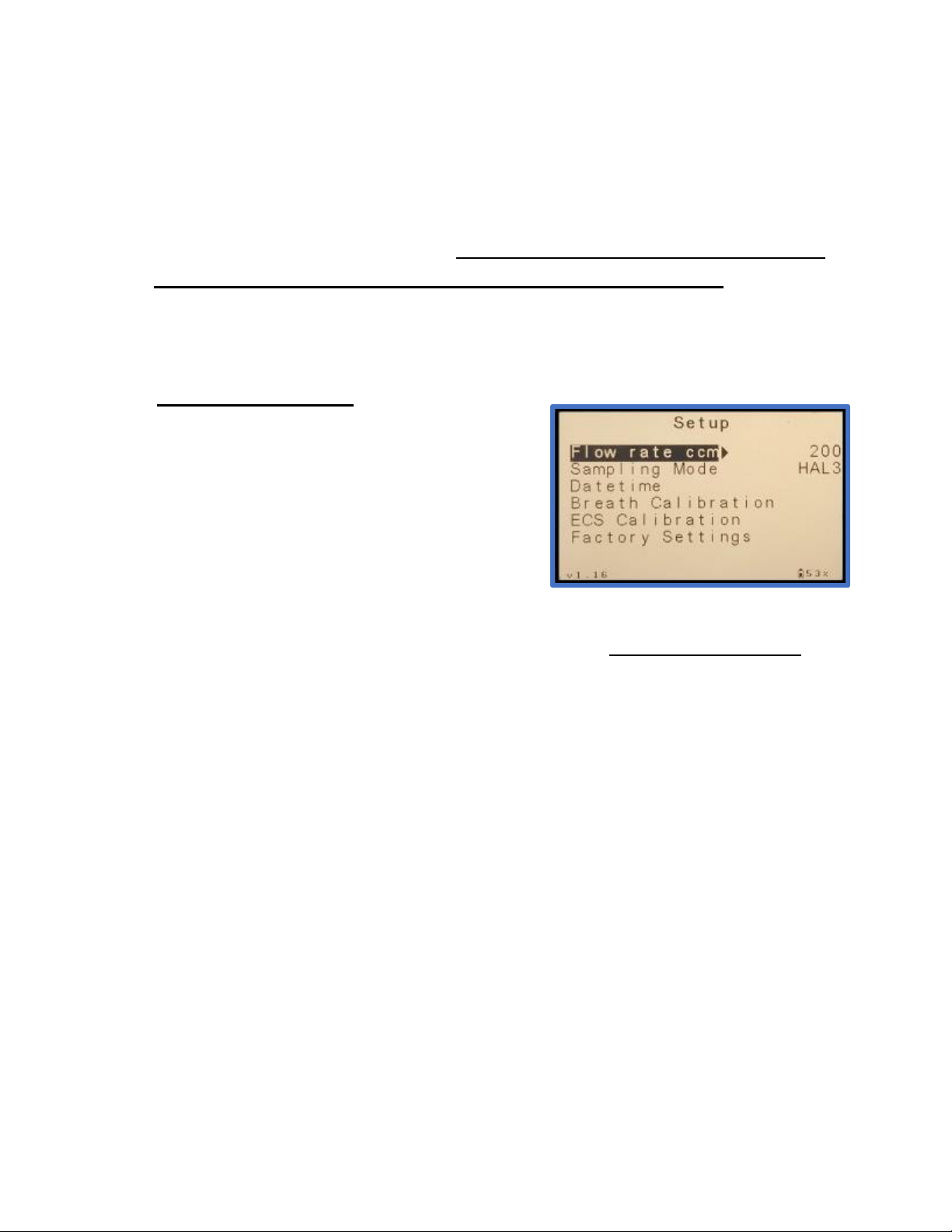
The Setup Menu shown on the right offers access
to parameters that may need to be changed for the
user’s particular application aswell as maintenance
functions. This menu is detailed below.
Flow rate –cc / min –Nominal setting = 200 cc / min. Do not change this setting.
Sampling Mode –Nominal setting = HAL3. This setting controls the SAMPLE
MODE procedure with 4 options as follows:
•Continuous - Sample is drawn continuously.
•HAL1 -Sample is drawn in a single cycle of 3-minute hold followed by a
35 second breath sample.
•HAL2 - Sample is drawn in 2 sample cyclesas noted in HAL1.
•HAL3 - Sample is drawn in 3 samplecycles as noted in HAL1.This isthe
default HalimeterPLUS sampling mode.
Datetime –Set the date and time according to the user’s time zone.
Breath Calibration –Provides for user calibration using a NORMAL BREATH
sample. See section 7 for details on calibration.
ECS Calibration –This feature is intended for non-Halimeter applications and will
not be used on the HalimeterPLUS.
Factory Setup –A password protected setup sub-menu for factory setup only.
3.6 SETUP MENU

120-00011 Rev. New
HalimeterPLUS User Manual 7/15/2020
13
Section 4 – Breath Sampling Considerations
The HalimeterPLUS is designed to reliably measure VSC (Volatile Sulfur Compound)
concentrations as part of a total program for the treatment of halitosis. Along with a
thorough history and physical examination of the patient, the quantitative nature of
HalimeterPLUSdatacanserveasanexcellenttoolforfollowingtheprogressoftreatment
and for archiving hard copy records.
A “normal” HalimeterPLUS reading is defined as a reading measured with a subject who
does not present with an apparent bad breath problem. Based on a statistical study of
several thousand individual HalimeterPLUS readings taken at INTERSCAN using
multiplesubjectsnot presentingapparentbreath problems,morethan90%ofthe readings
occur within a range of 80 to 120 ppb. The following scale can be used as a guide for
interpreting HalimeterPLUS readings.
1) Normal readings, for subjects with no oral malodor, are generally in the range of
80-120 parts per billion (ppb). Readings lower than this range are still indicative of
no oral malodor, and are otherwise clinically inconsequential.
2) At levels of 200-300 ppb, oral malodor is noticeable by an observer standing close
to the patient.
3) At 350-400 ppb, the odor is noticeable by an observer standing several feet away
from the patient.
4) At 500-700 ppb the odor is more noticeable not because it is “stronger,” but
because it is more foul.
5) At over 1000 ppb, the odor will linger for several minutes after the patient leaves
the room.
NOTE: Halimeter
PLUS data by itself cannot affirm whether a breath problem exists. The
dental practitioner is required to include the assessment of other diagnostic procedures
prior to making a positive conclusion.

120-00011 Rev. New
HalimeterPLUS User Manual 7/15/2020
14
4.1 SAMPLE INTERFERENCES
Part of ensuring accurate sample readings is minimizing sensor interferences that may
result in false readings. One of the most common interferences to the Halimeter® PLUS
sensor are vapors present in MOUTHWASH. The presence of residual mouthwash in
the mouth will produce a false Halimeter® PLUS reading and can seriously limit
sensor life.
Ifmouthwash is used prior to taking a Halimeter® PLUS reading,the mouth must be
rinsed thoroughly with water to clear out residual mouthwash solution. This must
be done at least 30 minutes prior to using the Halimeter® PLUS.
It is also recommended that the patient should refrain from eating, smoking, drinking
(water is allowed) and any oral hygiene activity for 3-4 hours prior to testing.
WARNING: THE SENSOR WARRANTY WILL BE VOIDED IF THE SENSOR IS
CONTAMINATED BY MOUTHWASH VAPOR OR THAT OF OTHER CONTAMINANT
LIQUIDS.
Other possible interference conditions include handling the sample tube connector while
the sensor is stabilizing. This should be avoided as substances on the hands may cause
false reactions and inhibit proper sensor stabilization.
4.2 PROPER SAMPLING TECHNIQUE
The manner in which the sample is collected is critical to obtaining accurate readings. The
proper sampling technique is described in detail below.
1) Ensurethat the sample straw is inserted FULLY into the sample tube connector
until it reaches the tubestop. If not fully inserted, sample may be lost to leakage
at the connector.
2) The patient’s mouth should remain closed prior to sampling to allow a full build
up of any VSCs present in the breath sample.

120-00011 Rev. New
HalimeterPLUS User Manual 7/15/2020
15
3) When ready to collect sample, the end of the sample straw should be inserted
into the patient’s mouth at a depth of approximately 1-2 inches (25-50mm)
resting on the back of the tongue. The lips should be almost closed allowing for
aslightgapbetweenthelipsandthesample straw.DO NOT PRESS THE LIPS
OR TEETH DOWN ON THE SAMPLE STRAW.
4) Breathing should continue THROUGH THE NOSE during sampling allowing
sample to be drawn from the mouth by the HalimeterPLUS pump rather than
forced in by the lungs.
5) DO NOT BLOW INTO THE SAMPLE STRAW AS THIS WILL AFFECT
SAMPLEACCURACY.Theflowindicatorshouldbemonitoredbytheindividual
supervising the breath test to ensure that the flow rate stays at approximately
200 ml/min and that it is not increasing or fluctuating as a result of the patient
breathing or blowing into the sample straw.
6) Typically,theppblevelwillriseduringthesampleperiodandreachapeakvalue
after which the value will begin to fall. When the sample ppb value begins to
decrease, the sample straw should be removed from the mouth and set down
until the next sample period at which point the sequence will be repeated.

120-00011 Rev. New
HalimeterPLUS User Manual 7/15/2020
16
Section 5 – Taking Breath Samples
After powering up the HalimeterPLUS, select MEASURE from the MAIN MENU by
pressing the RIGHT ARROW button. This will open SENSOR STABILIZING MODEand a
5-minute timer will elapse. Upon the timer elapsing, the instrument will automatically enter
OFF MODE.
From OFF MODE, press the ENTER button to advance to ONMODE. The pump will now
turn on. Allow the sensor several minutes to stabilize to ambient flow. You may notice the
flow rate reading fluctuates for several seconds before stabilizing at 200 mL/m. This
fluctuation is normal.
Once the reading has stabilized, the instrument is ready to be zeroed.
5.1 ZEROING THE HALIMETERPLUS
It is always a good idea tozero the HalimeterPLUS prior to sampling. To accomplishthis,
ensure the unit is in ON MODE and has been allowed to stabilize in this mode for several
minutes. Confirm that the flow rate has settled at 200 mL/m and the PPB display is not
rising or falling significantly. Zero the instrument as follows:
- Press the UP ARROW button. The ZERO
indicator will now be highlighted indicating
ZERO MODE is active.
- Press the ENTER button. “Set ZERO” will
display under the PPB display for 3
seconds indicating the display has been
zeroed.
- Press the DOWN ARROW button to exit
ZERO MODE.
The instrument is now ready for sampling.
120-00011 Rev. New
HalimeterPLUS User Manual 7/15/2020
17
5.2 TAKING SAMPLES
After zeroing the display, the instrument is ready for sampling. The following steps detail
the sample procedure:
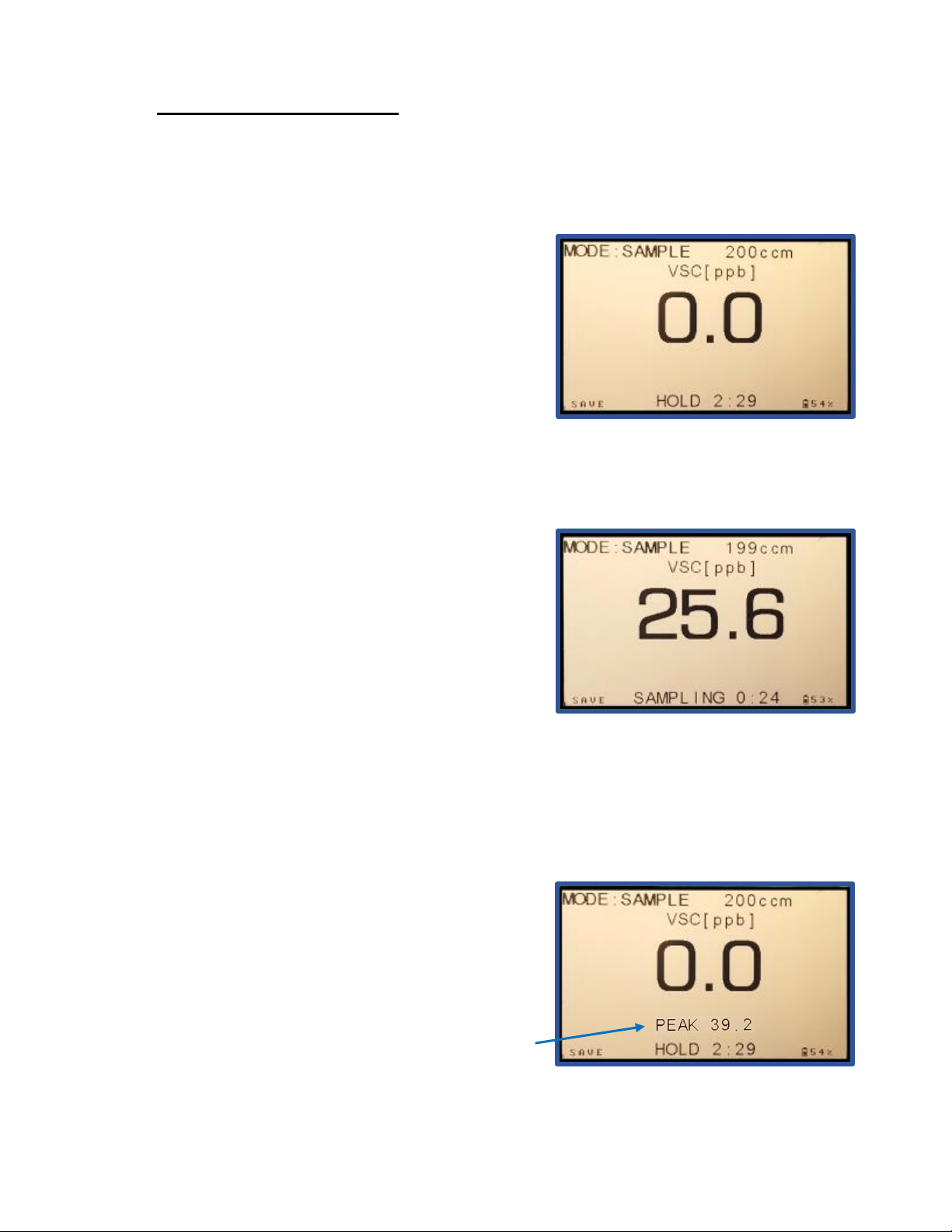
1) FromONMODE,presstheENTERbutton.This
will advance the instrument to SAMPLE MODE
starting a series of 3 sample cycles where 3
separate breath samples will be taken. The screen
shown to the right will be displayed which shows a
“HOLD” countdown timer at the bottom of the
display. During this 3-minute time period, the
patient should wait with his/her mouth closed to allow a proper breath sample to
accumulate. The patient should breath through the nose and refrain from talking.
2) When the countdown timer fully elapses, there
will be 3 rapid “beeps” indicating the start of the first
35-second sample period. The timer label will
indicate “SAMPLING” as shown on the right and
the timer will begin it’s 35 second countdown.
There will be a “beep” every 3 seconds during the
SAMPLEcycle.Atthispoint,the patient shouldput
the sample straw into his/her mouth as detailed previously in section 4.2. As sample is
drawn from the mouth, the displayed value will begin to rise until it hits a peak value after
which it will begin to decline. At this point the patient may remove the straw from his/her
mouth and wait until the next SAMPLE cycle withmouth closed.
4)AttheendoftheSAMPLEcycle, therewillagain
be 3 rapid “beeps” indicating the beginning of the
next HOLD cycle. The timer label will indicate
“HOLD” and the 3-minute timer will begin again.
The PEAK value from the SAMPLE cycle just
completed will be displayed above the timer
display. The patient should again wait with mouth
closed asinstep 1.

120-00011 Rev. New
HalimeterPLUS User Manual 7/15/2020
18
5) This HOLD/SAMPLING cycle will repeat for 3
total samples. A new PEAK value will be added for
each completed SAMPLE cycle above the timer
field. At the end of the third SAMPLE cycle, the
instrument will return to ON mode and the breath
value display will show the average of the 3 PEAK
sample values as indicated by “AVG” above and to
the right of the numeric display as shown to the right.
ThroughouttheSAMPLEMODEcycles, the display
can be toggled between a numeric value and a
graphical value by pressing the RIGHT ARROW
button to show graph display and the LEFT
ARROW button to return to numeric display. The
graphical display is shown to the right.
To begin a new SAMPLE MODE cycle for a new patient, press the ENTER button from
ON MODE. This will clear the previous AVG reading and the 3 PEAK values and start a
new series of readings. These display values can also be cleared without starting a new
cycle by pressing the STOP button successively until the MAIN MENU is displayed.
5.3 AUTO BLOCKAGE DETECTION
The HalimeterPLUS is equipped with flow rate
detection to protect against unwanted blockages in
the inlet line. In the event of a sudden drop in
flowrate in ON or SAMPLE modes, the screen
shown to the right will be displayed. This indicates a
blockage of the inlet tube that must be addressed
before sampling can resume.
Should thismessageappear,checkthetubingforanyblockagesorkinksthatmightrestrict
flow. Clear this blockage then press the ENTER button to proceed.
Table of contents


