inVue CT101 User manual

Peel the clear lm from the 2
adhesives on the bottom of the
swivel base.
CT101
Stand, Bases & Pucks
2e
Secure the swivel base to the stand
using the provided screw.
2c
Optional Swivel Base
(CT1012) Installation:
Remove the 2 adhesives from the
bottom of the stand.
2a Route the stand’s power cable
through the swivel base.
2b
Use the provided alcohol wipe to
clean the xture where the stand
will be placed. Allow it to dry
completely.
1
CONTENTS: One pad saturated in 75%
Isopropyl Alcohol
DIRECTIONS: Apply topically as
needed to cleanse surface mounting area.
FOR EXTERNAL USE ONLY
KEEP OUT OF REACH OF
CHILDREN
KEEP AWAY FROM EYES
AND FIRE
Optional:
If routing the power cable across the
xture surface, run the cable down
the channel in the bottom of the
base.
2f
Optional:
If using the stud mount option with the
swivel base, insert and tighten the stud
into the threaded hole.
Note: The use of the adhesives (see
the next step) is still recommended to
prevent the rotation of the base.
2d

Optional:
If routing the power cable across the
xture surface, run the cable down
the channel in the bottom of the
base.
3e3c Secure the adhesive base to the
stand using the provided screw.
Route the power cable through the
hole in the adhesive base.
3b Peel the clear lm from the 2
adhesives on the bottom of the
adhesive base.
3d
Press the stand against the xture for
at least 10 seconds.
2h Optional Adhesive Mount
Base (CT1013) Installation:
Peel the clear lm from the 2
adhesives on the bottom of the
stand.
3a
Optional:
If using the stud mount option from
Step 2d, beneath the xture, place
the large yellow washer onto the
stud and thread the wingnut onto the
stud. Fully tighten by hand to secure
the stand.
2i
Optional:
If routing the power cable through a
hole in the xture, insert the cable into
the hole.
2g

4b Route the power cable through the
hole in the wall mount plate.
4a Optional Wall Mount Plate
(CT1014) Installation:
Peel the clear lm from the 2
adhesives on the bottom of the
stand.
4c Secure the wall mount plate to the
stand using the provided screw.
Optional:
If routing the power cable across the
xture surface, run the cable down
the channel in the bottom of the
base.
4d 4f Secure the stand using 4 screws (not
supplied) that are appropriate for the
xture material.
4e Optional:
If routing the power cable through
a hole in the xture, insert the cable
into the hole.
3g Press the stand against the xture for
at least 10 seconds.
3f Optional:
If routing the power cable through
a hole in the xture, insert the cable
into the hole.

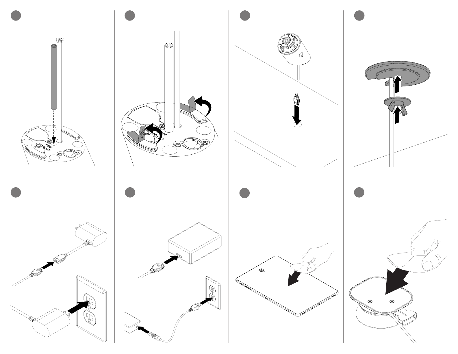
Route the power cable and stud
down through a hole or slot in the
xture.
5c From beneath the xture, place the
large yellow washer onto the stud
and thread the wingnut onto the
stud. Fully tighten by hand to secure
the stand.
5d
If using a device with a micro-USB or
Lightning connector use the PS531
power supply. Plug the stand’s power
cable into the power supply and plug
the power supply into a power outlet.
6a 7Adhesive Puck Installation:
Clean the back of the device being
mounted using the provided alcohol
wipe. Allow it to dry completely.
CONTENTS:
Isopropyl Alcoho
Peel the clear lm from the 2
adhesives on the bottom of the
stand.
5b5a Stud Mount (Included With
CT1011) Installation:
Insert the threaded rod into the hole
in the bottom of the stand.
If using a USB-C device use the
PS564 power supply. Plug the
stand’s power cable into the power
supply. Connect the power cable to
the power supply and plug it into a
power outlet.
6b Use the alcohol wipe to clean the at
surface on the puck. Allow it to dry
completely.
8

Optional:
Peel the clear lm from the adhesive
on the power connector shroud.
13a13a Position the power connector shroud
onto the back of the device so that it
hooks around the power connector.
Apply pressure for at least 10
seconds.
13b13b Optional:
If there is slack in the power
connector cable, use the cable
manager to contain it by rst
removing the clear lm from the 2
adhesives.
14a14a Pull the power connector cable
gently across the back of the device
to remove the slack and place the
cable manager over the cable to hold
it in place. Apply pressure for at least
10 seconds.
14b14b
Center the puck on the back of the
device and apply pressure for at least
10 seconds.
12
11 Peel the clear lm from the adhesive
on the puck.
10 Plug the power connector on the
puck into the device.
Remove the adhesive from its backing
and place it on the puck. If there is a
yellow plunger present on the puck,
ensure that it ts into the cutout on the
adhesive. Apply pressure for at least
10 seconds.
9

SD0765 Rev1 03/24/20
© 2020 InVue Security Products Inc. All rights reserved.
InVue is a registered trademark of InVue Security Products.
www.invue.com
NA / LATAM // 704.752.6513 •888.55.INVUE
EMEA // +31.23.8900150
APAC // +852.3127.6811
Place a coded CT Key or OneKEY
against the lens on the side of the
stand and press the button on the
key to transfer the store code to the
stand. This method is also used to
release the device and puck from the
stand.
16
Place the device and puck onto the
stand.
15
Table of contents
Other inVue Tablet Accessories manuals