Ipcam AJ Series User manual

Wireless/Wired Network IP Camera
(For PC View)
Night Vision & Remote
Operation
User
Manual
0

Thank you for buying our IP camera
IPCAM AJ Series IP Camera products are designed and equipped for local and remote
network video surveillance system, including wired IP bullet camera, wireless IP bu
ll
et
camera, IP IR dome camera, IP IR waterproof camera, IP Pan/Tilt/Zoom Camera etc. We
adopt high performance chip to ensure high quality media processor which processes
audio and video collection, compression and transmission. Standard M-JPEG
compress
i
on format ensures clear and streaming video performance. It enables users to
view live video via IE6.0, IE7.0, IE8.0, Firefox, Google browser or other standard browser
IPCAM AJ series IP Camera products are applicable for big, medium-sized and small
enterprises, chain store, factory, home and all kinds of spots where remote network video
transmission and control supposed to be installed, they are easy to be installed and
operated. Before the installation of the IP camera, please check if your product
accessor
i
es in the package are comp
l
ete
Packing L
i
st
Untie the pack and check the items contained against the following
list:
●IP Camera X1
●Warranty Card X1
●DC Power Supply X1
●CD X1
●Certificate of Quality X1
●Mounting bracket X1
NOTE: Please contact us immediately if anything damaged or short of contents
.
1

Table of CONTENTS
1. Product Introduction
...........................................................................................3
1.1. Safety Introduction
.........................................................................................3
1.2. Product Specifications....................................................................................
....3
1.3. System
Requirements........................................................................................3
1.4. Product
Views……………..............................................………….................4
1.4.1 Front View................
......................................................................................4
1.4.2 Interface
View.................................................................................................5
1.5. Hardware
Installation........................................................................................5
1.6. Software Installation.....................................
....................................................6
2. Software
Operation...............................................................................................6
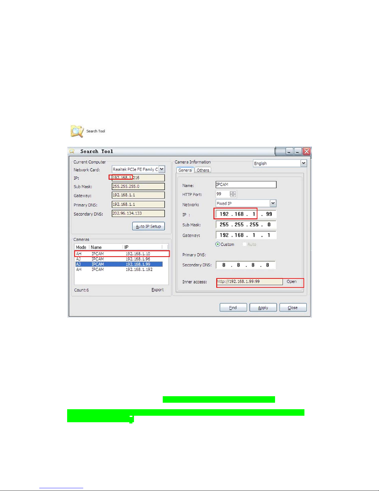
2.1. Search Tool Software.................................................
......................................6
2.1.1. Search The IP address of the
Camera.............................................................6
2.1.2. Configuration of the Network............................
............................................7
3. Real-Time Video Demonstration...................................
......................................9
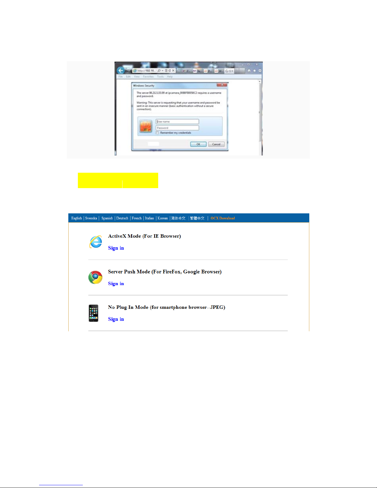
3.1. Camera Login.............................................................. ..................
...................9
3.2. View via IE
Browser.........................................................................................10
3.3. View via Safari, Firefox, Google Browser. ..................
...................................13
3.4. Main Menu interface Introduction.......
............................................................14
3.5. Administer Setting Instruction.........................
................................................15
3.5.1. Multi-Device
Settings....................................................................................16
3.5.2. Basic Network Settings..............
...................................................................17
3.5.3. Wireless Settings..........................................................
.................................17
3.5.4. Dynamic DNS
Settings...................................................................................18
3.5.4.1. DDNS Setting
.............................................................................................18
3.5.4.2. Port Forwarding Settings.........
...................................................................20
3.5.4.3. DDNS Register........ ..................
................................................................23
3.5.5. Email and FTP Service Settings.......................
.............................................28
3.5.6. Alarm Service Settings.............................
.....................................................29
3.5.7. Reset/Firmware Upgrade Settings...............
..................................................29
3.5.8. Record&Capture Path..........................
..........................................................30
3.5.9. Reset/Firm Ware
Upgrade...............................................................................30
3.5.9.1.Restore Factory
Settings................................................................................31
3.5.9.2. Reboot
Equipment........................................................................................31
4.
Warranty................................................................................................................31
2

1. Product
Introduction
1.1 Safety Instructions
(1). Use the proper power
source.
Do not use this product with a power source that supplies more than the specified Vo
l
tage
(100-240V AC)
.
(2). Never insert anything metallic into the
camera.
Inserting metal object into the camera can be a source of dangerous electric shock
.
(3). Do not operate in wet or dusty
environment.
Avoid places like a damp basement or dusty ha
ll
way
.
(4). Do not attempt to disassemble the
camera.
You may be subjected to severe electrical shock if you attempt to take apart the camera
while the camera is connected to its power source. If there are any unusual sounds or
smells coming form the camera, unplug it immediately and contact Customer Serv
i
ce
.
(5). Handle the camera
carefully
Dropping the camera on any hard surface may cause a malfunction. If the camera does not
work properly due to physical damage, please contact Customer Service for repair or
exchange
.
(6). Apply to FCC and CE
Rule
This device complies with part 15 of the FCC and CE Rules. Operation is subject to the
following two cond
i
t
i
ons:
1: This device may not cause harmful
i
nterference
.
2: This device must accept any interference received, including interference that may
cause undesired operat
i
on
.
Any changes or modifications not expressly approved by the party responsible for
compliance could void the user’s authority to operate the equipment. This equ
i
pment
complies with FCC and CE radiation exposure limits set forth for uncontro
ll
ed
env
i
ronment
.
This equipment should be installed and operated with minimum distance 20
cm between the radiator & your body
.
This transmitter must not be co-located or operating in conjunction with any other antenna
or transm
i
tter
.
1.2. Product Specifications
*- Adopt high Performance, strong function media processor 32Bit RS
I
C
*- High sensor CMOS
*-Adopt optimized MJPEG video compression algorithm, realize high-definition
i
mages
transmission in narrow bandw
i
dth;
3

*-Maximum support 15 users viewing at the same time, no limit for users if using forwarder
Server funct
i
on;
*- Built in Web Server, convenient for users to use standard browse to realize the
real time monitoring and setting adm
i
n
i
strat
i
on;
*-Support WIFI:802.11 b/g/n wireless network
i
ng;
*-Support remote system update;
*-Support DDNS analysis, support LAN & Internet (ADSL,Cable Modem)
*-Support variety of network protocol: TCP/IP, UDP, SMTP, PPPoE, Dynamic DNS
,
DNS Client, SNTP, BOOTP, DHCP, FTP, SNMP, WIFI/802. 11b
/
g
*-Parts of modes products support one/ two way audio, ta
l
kback;
*-Support motion detection alarm function (area & sensitivity Conf
i
gurab
l
e);
*-Support image snapshot
*-Abnormal automatic recovery function, auto reconnection available when network
Interruption occurred
.
*-Dynamic alarm function, alarm time-schedule conf
i
gurab
l
e
.
1.3. System Requirements
1.4. Product Views
1.4.1 Front View 1.4.2 Interface
View
4

Figure 1.1 Figure 1
.
2
1: Audio Out , 2: Audio
I
n
3: Ethernet interface: RJ-45 interface. Power Supply Light: constant on after power up
Network light: constant sparkle after power up data transm
i
ss
i
on
.
4: Antenna:
5: Power input interface: connect direct current 5V Power
1.5 Hardware Installation
Follow the steps below to set up your camera hardware. Make sure to follow each step
carefully to ensure that the camera operates proper
l
y
1. Install the Wi-Fi antenna (For wireless model)
.
2. Plug the power adaptor into camera
3. Plug the network cable into camera, the other side to the router
/
sw
i
tch
4. It takes approx 30 seconds to boot up the camera, then you will find the IP address from
“Search Tool” (Figure: 1
.
8)
5. When the power on and network cable connected, the green led of the real panel w
ill
keep on, The yellow led will keep f
l
ash
.
5

Figure 1
.
3
1.6 Software Installation
Figure 1
.
4
Open the CD Install the follow software:
1. ActiveX: Click “OCX setup”—“Next”—“
I
nsta
ll
”—“F
i
n
i
sh”
.
2. Search Tool: Open the CD, click ,The Search Tool will run
automatically.( No need to install. You can copy this software to your desktop
.
)
Figure 1
.
5
6

Mak
e
su
r
e
the “Subne
t
Mask”
y
ou
r
c
u
r
r
en
t
compute
r
s“DNS Ser
v
e
r
”
i
s
th
e
sam
e
2. Software operat
i
on
2.1 Search Tool Software
2.1.1 Search the IP address of the
camera
.
When the device has been mounted properly, you can double click the
I
con
“” run this IP address search too
l.
Figure 2
.
1
Note: The software searches IP Servers automatically over LAN
.
There are 2 cases:
1. No IP Cameras found within LAN. After about 1 minute search, the Equipments L
i
st
Field not show the IP address
.
2. IP Cameras have been installed within LAN. All the IP Cameras will be listed and the
total number is displayed in the Equipments list field as shown in Figure 2
.
1
Note:
1. Current Computer indicates the Computer’s IP Address in
f
orma
t
ion
.
2. Equipment information indicates the IP camera’s IP Address in
f
orma
t
ion
.
3. If you find that the camera’s “Subnet Mask”, “Gateway”, “DNS Server” is not as
some as your current computer’s. You need try to change the camra’s IP address
.
, “Gateway”
,
as your router’s or
7

Subne
t
Mask
,
Gatewa
y
,
DNS Ser
v
e
r
4. If you don’t know how to configure your camera’s IP address. You can c
li
ck
“ Update” button. The Search Tool software can help you configure a usable IP camera
automat
i
ca
ll
y
.
2.1.2 Configuration of the
Network
Once your camera’s IP address
’
is the same as your
PC or router, you need configure the camera’s Network parameter manua
ll
y
.
IP address: Fill in the IP address assigned and make sure it is in the same subnet as
t
he
Gateway, and the subnet should be the same as your computer or router. (i.e. the first
t
hree
sections are the same)
Subnet Mask: The default subnet mask of the equipment is: 255.255.255.0. You can find
t
he
subnet mask from your PC or rou
t
er
.
Gateway: Make sure it is in the same subnet with PC’s IP address .Here gateway is the LAN
I
P
of your rou
t
er.
Primary DNS: IP address of IPS network provider. You can also set it as the same as
t
he
Ga
t
eway.
NOTE: You can find out the Subnet Mask, Gateway, Primary DNS of your PC from
t
he
“Search Tool” so
ft
ware
.
Http Port: LAN port assigned for the equipment, default is 99. You can change the port number
to any one you want such as : 98,211,9999 e
t
c.
3: Real-time Video Demonstrat
i
on
.
3.1. Camera
Login:
You can access the camera through IP Camera Tool or IE, Firefox, Safari, Google
Chrome or other standard browser directly.
1. Double click the IP address of the IP Camera listed (Figure 2.1). The default
browser you use will run automatically and come to the camera login interface.
(Figure 3.1)
2. To access the camera by IE Browser directly, just type the camera’s IP address, for
example, if the camera’s IP address is 192.168.1.99:99:
8

Figure 3
.
1
Defaul
t
username: admi
n
Passwo
r
d: no
p
asswo
r
d.
Input the correct user name and password, the Sign In interface will pop-up.
There are three models to login (figure 3.2).
Figure 3
.
2
(1) ActiveX Mode (For IE Browser): available in IE6.0 or above explorer
(2) “RTSP Stream Mode”: available in Firefox, Safari, and Google browser.
(3) “No Plug-In Mode”: available in smart phone browser.
(4) SD card video playback online
3.2. View via IE
Browser.
9

Choose Active Mode (For IE Browser), and sign
i
n
.
The first time login the camera, maybe get ActiveX prompt as the picture below, p
l
ease
download the Ocx(or run in CD) and install first then choose Run Add-on,
refresh and login the camera again, then will see live video, details as be
l
ow:
Figure 3
.
3
After Download Ocx-Setup (oPlayer Software), Click and install it, untill f
i
n
i
shed
.
Figure 3
.
4
10

Figure 3.3 Windows XP system
Figure 3.4 Win7 System
Note: If there is still no live video after run ActiveX, please try to enable the Act
i
veX
options of IE security settings, please do the follow steps:
1. Close the firewall of your computer
.
2. Change the ActiveX settings, “IE” browser > “Tool” > “Internet Options” > “Secur
i
ty”>
“Custom Level” > “ActiveX control and Plug-ins”, all the ActiveX options set to be
“Enable”: Espec
i
a
ll
y:
Enable: Download unsigned ActiveX contro
l
s
Enable: Initialize and script ActiveX controls not marked as safe
Enable: Run ActiveX controls and p
l
u-
i
ns
11

Figure 3
.
5
Figure 3
.
6
In Addition: you can also click “start” menu->“Internet Explorer”, choose “
I
nternet
attributes “ to enter, or via “Control Panel” ->“Internet Explorer”, enter to Security sett
i
ng
.
3. If there is still no image, please close your anti-virus software, and then try step 1 & 2
aga
i
n
.
4. If you allowed the Active X running, But still could not see live video, Only a Red
Cross in the center of the video, And the device status light change to ye
ll
ow
color , not green please change another port number to try, Don’t use port 80, usd other
port such as99, 199 etc
.
12

Figure 3
.
7
NOTE: Make sure that the firewall or anti-virus software doesn’t block the software or
ActiveX. If you couldn’t see live video, please close your firewall or anti-virus software
,
and try aga
i
n
.
3.3. View via Safari, Firefox, Google
Browser
Choose Server Push Mode (For Safari, Firefox, Google Browser), and sign
i
n
Server Push Mode doesn’t support ActiveX, so some functions are not available, such
As Record, Audio, Talk, Speaker,The speed control bar, Zoom etc.),if you want to use
these functions, please use IE Browser
.
The Control Interface in this mode is as be
ll
ow:
13

3.4. Main Menu interface
introduction
Take the “Active Mode(For IE Browser)” For example:
14

Figure 3
.
8
the cameras have this Pan/Tilt funct
i
on
.
The Pan/Tilt Feature only work when
This option enables log detection. After the online user clicks this button, a log
i
s
entered into the camera’s Log Data documenting the IP address of users who have
accessed the IP camera. This Option enables alarm detections too
.
This button make the camera Vertical cruise (for the Pan/Tilt Cams)
.
This button make the camera Level cruise (for the Pan/Tilt Cams)
.
This button flips the image vert
i
ca
ll
y
.
This button flips the image hor
i
zonta
ll
y
.
This button for turn on and turn off the IR LED L
i
ght
.
Control the speed of the Pan/tilt. Only work for the Pan/tilt Cams
.
Cams This button for setting the Preset of the camera. Only work for Pan
/
t
il
t
This setting changes the color of the OSD
l
etter
i
ng
.
This setting changes the image reso
l
ut
i
on
.
15

This setting changes the image frequency
.
This setting changes the image br
i
ghtness
.
This setting changes the image contrast
.
This option resets all main menu options to factory defau
l
t
.
This option opens the camera’s recording functionality menu
.
This option takes a snapshot of the current screen and saves the snapshot to the
PC’s Hard Dr
i
ve
.
This option enables User-to Camera audio. If the online user
This option enables Camera-to-User audio. If the online user has speakers connected
and configured to their PC, clicking this option will allow them to hear audio from the
location of the camera
.
This button opens the IP camera’s Backend Menu
These options enable single view, quad screen view, or 9 screen v
i
ew:
This function serves no purpose unless you have more than one camera connected and
configured to your
i
nterface
.
* Please refer to section 8.1.1 Multi-Device Sett
i
ngs*
Open and close the infrared function. IR On,IR OFF
3.5. Administer Setting
Instruction
When login as Administrator, you can enter the IP Camera for Adm
i
n
i
strator
.
Administrator supports all the settings and operations of the camera; you can set and
control it freely There are some special functions only for administrator as be
l
ow:
Alias setting : You can set your favorite device aliases.
Date&Time set : seting the date and
t
ime
.
Uer settings : Can be set up to 8 users. On this pageyou can set up accounts of the user name
,
password, as well as in their packet (administrator, operator, visi
t
or)
.
�
Visitor : In this mode, you can only visi
t.
�
Operator :You can set the direction of the lens device, set the video screen’s brigh
t
ness,
contrast and other parame
t
er
.
�
Administrator : You can set the device advanced con
f
igura
t
ion
.
UPnP set :If you want internet access IPCAM, to ensure that the state issuccessful UPnP
.
Device Firmware Upgrade: The system firmware update the device firmware and application o
f
Restore factory settings : When there is not a response when the error occurred, you can
restore the factory settings to resolve the device
.
I rebooted the device : rebooted the device
.
Back: Return to monitor mode
3.5.1 Multi-Device Settings
�
Add a local area network equ
i
pment
In the multi-device configuration page, you can see all the equipment inside the LAN
.
The first device is the default device. You can add more devices listed in the list of
16

equipment. Embedded applications, up to 4 devices at the same time-line. Click the
“second road equipment” and double-click “Current list of devices in the LAN” in the
device entry name, host address, Http port will automatically be filled, require the user to
fill in the correct account name and password, click “Add.” Repeat this process you can
continue to add devices. Finally do not forget to click on the “Settings” button
.
Figure 3
.
9
3.5.2 Network Settings
Figure 3
.
10
17

Figure 3
.
11
This sector is for DHCP and IP configuration, port forwarding is needed, If you
choose to set IP address,please fill in the relative IP address, subnet mask, gateway, DNS
server, Http port
;
3.5.3 Wireless Settings
1. Make sure the router is a wireless router
.
2. Make sure the Wi-Fi antenna
i
nsta
ll
ed
.
3. Make sure whether there is encryption of the WLAN of the router, if there is encrypt
i
on
,
keep the key
.
4. Login the camera, click >“Wireless Lan Settings”>”Scan”, please scan 2times,
then you will find the WLAN from the list, choose the one you use
.
5. If there is no encryption, just click “Submit”, if there is encryption, please input the key
,
then click “Subm
i
t”
.
6. Wait about 30 seconds, the camera will reboot, then unplug the network cab
l
e
.
18

Figure 3
.
12
3.5.4 Dynamic DNS Setting (DDNS)
3.5.4.1 DDNS Setting:
(1): Click > “DDNS Service
Settings”.
Figure 3
.
13
(2): Choose the DDNS, there are 4 kinds of
options:
(1): Manufacturer’ DDNS: We provide a free DDNS: vipcam.org. This domain is prov
i
ded
by manufacturer
.
Note: 88safe.com is old DDNS provided by manufacturer also. If you want use the manu
f
acturer’s
free DDNS, Please Choose to use vipcam
.
org
.
19
Other manuals for AJ Series
1
Table of contents
Other Ipcam IP Camera manuals