ipf electronic OC29 X.Lite ProCap User manual

TABLE OF CONTENTS
1. Important symbols .....................................................................................................................................................2
2. Safety instructions for use..........................................................................................................................................2
3. General .......................................................................................................................................................................3
3.1. Document scope................................................................................................................................................3
4. System components ...................................................................................................................................................3
4.1. For whom is this manual intended? ..................................................................................................................3
4.2. Intended use......................................................................................................................................................3
4.3. Disposal .............................................................................................................................................................3
5. Installation..................................................................................................................................................................4
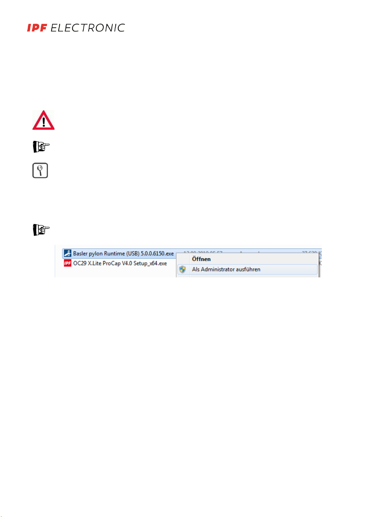
5.1. USB 3.0 driver installation .................................................................................................................................4
5.2. OC29 X.Lite ProCap installation .........................................................................................................................4
5.3. Important notes.................................................................................................................................................4
6. Basic settings ..............................................................................................................................................................5
6.1. Activating the camera........................................................................................................................................5
6.2. Memory limit .....................................................................................................................................................5
6.3. Language selection ............................................................................................................................................5
7. operation of OC29 X.Lite ProCap................................................................................................................................6
7.1. Overview............................................................................................................................................................6
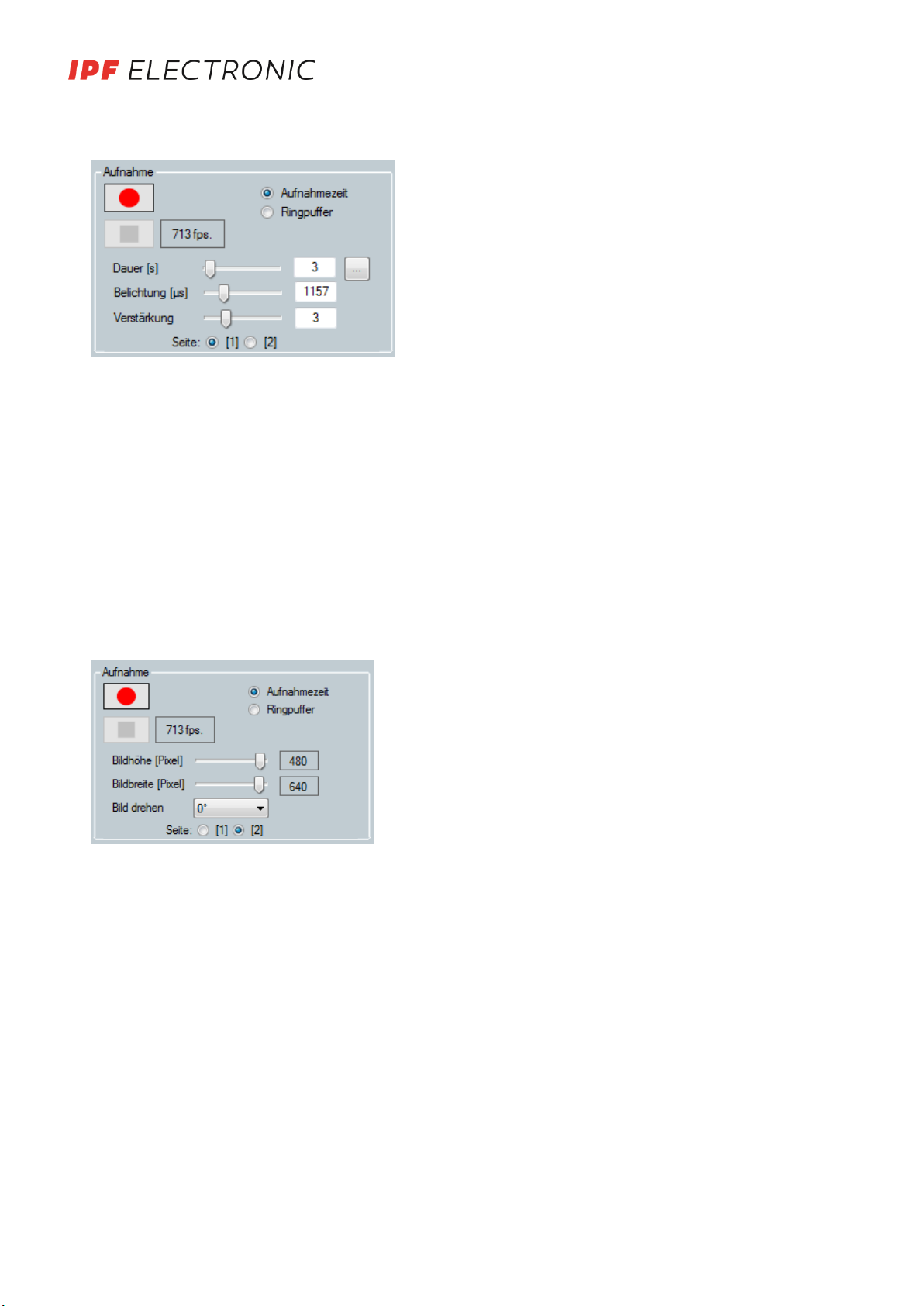
7.2. Recording...........................................................................................................................................................7
7.3. Play back............................................................................................................................................................8
7.4. Save/load.........................................................................................................................................................10
8. Automate OC29 X.Lite ProCap .................................................................................................................................11
8.1. Basic selection, signal sources and trigger mode ............................................................................................11
8.2. Digital trigger mode.........................................................................................................................................12
8.3. Use of interface protocols ...............................................................................................................................12
9. Hardware..................................................................................................................................................................13
9.1. PC/Laptop ........................................................................................................................................................13
10. Notes....................................................................................................................................................................14
11. License conditions................................................................................................................................................14
MANUAL •Subject to alteration! Version: September 2019
ipf electronic gmbh • Rosmarter Allee 14 • 58762 Altena │Tel +49 2351 9365-0 • Fax +49 2351 9365-19 │[email protected] • www.ipf-electronic.com
1

1. IMPORTANT SYMBOLS
This warning triangle indicates special safety instructions and warnings, which, if not observed,
may result in special cases in:
•Personal injuries and/or
•Significant property damage may occur
Indicates a source of electrical danger
Notes
Includes important additional information OR indicates that care is required to proceed
Explanation
Marked text positions that provide background information and that are important for explana-
tion of their importance
2. SAFETY INSTRUCTIONS FOR USE
In case of use in an industrial plant environment, the safety instructions of the plant manufacturer and the operator of
the plant shall apply above all!
Structures in the environment around the plant may only be completed by personnel with corresponding technical
qualifications. These persons must be aware of possible dangers.
All works in the environment of the plant must be completed free of voltage (main switch shut off) and free of pres-
sure.
The plant must be locked off against unintended activation during setup and tear-down work. Caution against danger-
ous residual energy in the system!
In case of mechanical work (attachments), the personnel must observe the load supporting values of all parts and pre-
vent possible dangers.
Lay out the cables so that no one is able to step on them or trip over them!
Prior to start-up, inspect the correct electrical activation of the camera!
In case of property damage and personal injury that are caused by incorrect handling or failure to observe safety in-
structions, we shall not be liable. The guarantee shall expire in these cases.
Never replace the components with another type of component. Any use of other components than those in their
original condition shall require inspection by the manufacturer and their written approval!
A guarantee may only be provided following correct use together with the included components.
Never look directly into the LED lamps. High-speed recordings require very bright illumination that may be damaging
to the human eye.
Handle the components of the highspeed camera with care. The illumination, lenses, and cameras in particular require
careful handling. These components may only be cleaned with special lens cleaning brushes.
OC29 X.Lite ProCap is not a toy and does not belong in the hands of children. Operate it outside of the reach of chil-
dren. Keep the packaging material, e.g. foil, away from children. Danger of asphyxiation in case of misuse.
The product is not approved for use in safety-relevant applications. If use in a safety-relevant application is planned,
the customer shall be responsible for the required approvals.
MANUAL •Subject to alteration! Version: September 2019
ipf electronic gmbh • Rosmarter Allee 14 • 58762 Altena │Tel +49 2351 9365-0 • Fax +49 2351 9365-19 │[email protected] • www.ipf-electronic.com
2

3. GENERAL
OC29 X.Lite ProCap is a high-speed process tracing system in the medium performance and price segment. USB3 is
used to transfer the images directly and quickly to the PC/laptop. Next, the available documents/media are listed and
the use and disposal are defined.
3.1. Document scope
-Product data sheet
-Manual (this document)
Information relevant within the scope of OC29 X.Lite ProCap are covered within the scope of this documen-
tation. Information that goes beyond this shall be indicated at the appropriate positions (mainly in the hard-
ware chapter).
4. SYSTEM COMPONENTS
The core components of the OC29 X.Lite ProCap system are a USB3 camera, the associated transmission cable, and
the software (supplied on USB stick) for recording and depicting image data. The system can be adjusted to the re-
spective requirements by adding additional accessories.
An overview of the currently available system components is provided in the "Hardware" chapter.
4.1. For whom is this manual intended?
This manual is intended for all persons who set up, put into operation, dismantle, carry out maintenance and operate
the OC29 X.Lite ProCap system.
It must be ensured that the operating personnel and all additional personnel who come into contact with the the
OC29 X.Lite ProCap system have read and understood this user manual.
4.2. Intended use
The OC29 X.Lite ProCap system is used for the analysis and documentation of very fast industrial processes (handling
tasks, presses, etc.).
In this case, read the safety conditions for use within plant environments in chapter 2!
Observe the guarantee instructions with regard to functionality and performance with the installation instructions
(following chapter) and system requirements (hardware chapter)!
4.3. Disposal
During disposal, local regulations concerning the respective components must be observed!
MANUAL •Subject to alteration! Version: September 2019
ipf electronic gmbh • Rosmarter Allee 14 • 58762 Altena │Tel +49 2351 9365-0 • Fax +49 2351 9365-19 │[email protected] • www.ipf-electronic.com
3

5. INSTALLATION
Installation of the OC29 X.Lite ProCap oftware and the required components as well as the basic configuration are de-
scribed in the following. The required installation programs are provided on a USB stick, which also includes the acti-
vation code for the associated camera. The basic files for operating the camera are included in the "Main compo-
nents" folder. Use the automation option via protocol to find the required additional components in the "Additional
tools" folder.
Close all other programs during the installation and configuration processes! Make sure that you have full
administrator rights for your PC or find the responsible administrator at your company!
Ensure back-up copies are created regularly, adjusted to reflect hazards!
The functions of the licensing system and liability conditions for the OC29 X.Lite ProCap software and soft-
ware of partner companies are provided in the appendix!
The software may be installed on multiple computers. Use is activated by entering an activation code related to
the camera serial number.
5.1. USB 3.0 driver installation
To operate the camera, installation of a USB3.0 driver is required which is carried out via the manufacturer's installa-
tion routine and must be carried out prior to the installation of OC29 X.Lite ProCap. Further information on installation
is provided depending on the camera model.
Plug in the camera after first installing the drivers!
-Open the application „Basler pylon Runtime“ as administrator (right click) and follow the instructions.
-Nach abgeschlossener Treiberinstallation USB 3.0 Kamera an einen freien USB-Port anschließen, die entspre-
chenden Treiber werden geladen
5.2. OC29 X.Lite ProCap installation
-Run „OC29 X.Lite ProCap Setup_x64“ as administrator (right-click)
-Follow the instructions of the installation assistant
5.3. Important notes
-We recommend closing unnecessary programs before starting OC29 X.Lite ProCap in ordert o free up RAM
(longer recordings are possible)
-You must possess full access permission in the Windows folder structure (at least in the installation folder for
OC29 X.Lite ProCap and its subfolders)!
-Attention: In the case of multiple saving processes (continuous saving via triggering), the use of a memory
stick is recommended. (especially if you use an SSD: limited number of writing processes)!
-The main interface is used for error analysis and to compare multiple processing runs. The maximum number
of images are worked with at the maximum resolution in this case!
-Take care in case of strong static charges (avoid these ideally!): this may cause the camera to malfunction –
normally this may be corrected by disconnecting and connecting and restarting the program!
-The screen saver must be deactivated if recording for a long time!
-Ensure that the camera is connected to a USB3.0 port!
MANUAL •Subject to alteration! Version: September 2019
ipf electronic gmbh • Rosmarter Allee 14 • 58762 Altena │Tel +49 2351 9365-0 • Fax +49 2351 9365-19 │[email protected] • www.ipf-electronic.com
4

6. BASIC SETTINGS
The following configuration is located in the basic settings selection:
1. Clicking on the <Activate camera> button opens a new window in which the acti-
vation code for a camera can be entered.
2. How much RAM the system has available in reserve can be defined in this text
field. The maximum recording time will be influenced as a result.
3. You can switch between different languages here.
6.1. Activating the camera
When the program starts for the first time, the program detects that the camera is not activated, and the following
dialogue box opens automatically.
Select a save location and copy the activation code from the file "Freischaltcode.txt" (on USB stick or may be sent by
e-mail) into the code line and confirm this via activation.
6.2. Memory limit
OC29 X.Lite ProCap records the image data directly into RAM, which is managed by Windows. Since the system behav-
ior varies considerably with regard to the maxi mum use of RAM in this case, OC29 X.Lite ProCap reads in the available
amount of RAM continuously during a recording. In order to prevent putting the function of Windows or your com-
puter at risk, an adjustable range is left free (value in limit memory, units in MB).
The actual values can be seen in the Task Manager:
In A value of 1,000 MB was proven to be effective in our tests. Smaller values can lead to a total crash of
Windows depending on the system settings.
These settings are useful at lower capacities, carefully navigate your way to an optimal value using trial and
error.
6.3. Language selection
OC29 X.Lite ProCap also provides the option of switching between German, English, Spanish and Italian. To do this,
simply select the desired language in the basic settings.
1
2
3
MANUAL •Subject to alteration! Version: September 2019
ipf electronic gmbh • Rosmarter Allee 14 • 58762 Altena │Tel +49 2351 9365-0 • Fax +49 2351 9365-19 │[email protected] • www.ipf-electronic.com
5

8
9
10
6
7
7. OPERATION OF OC29 X.LITE PROCAP
This chapter describes the extensive controls featured in OC29 X.Lite ProCap. The concept is designed so that the pri-
mary basic functions are displayed and additional functions and settings options are able to be activated additionally.
In this document, the controls and their functions are explained.
7.1. Overview
1
2
3
4
5
1. Recording functions
2. Optimieren Optimisation of the display when playing back and recording
Play back speed: Play back recording quicker or slower
Maximum view: An image is displayed at the maximum size in regards to the aspect ratio → Maximizing can
lead to very rough images with very low picture detail!
3. Functions for the playing back of recordings
4. Functions for saving and exporting recordings
5. Displays the additional options on the right side of the image area. The camera can be initialized with <Reset
camera> in the event of recording errors.
6. Position the mouse in this area and the serial number of the camera (if connected) and the software version
are displayed
7. Status bar with function display and additional status information
8. Display area
9. Functions for the automation of OC29 X.Lite ProCap
10. Other settings and additional features - explanations on these can be found in the basic settings subject area
(see above), playing back and recording
MANUAL •Subject to alteration! Version: September 2019
ipf electronic gmbh • Rosmarter Allee 14 • 58762 Altena │Tel +49 2351 9365-0 • Fax +49 2351 9365-19 │[email protected] • www.ipf-electronic.com
6

7.2. Recording
1. Start and stop recording
2. Displays the current frame rate (frames per second). Can be reduced under <Advanced settings>, see further
below
3. Recording mode selection
Recording time: Recording stops after a set time, see point 4
Ring buffer: The first images are overwritten again after a set time– can be stopped via the stop button. If the
capacity limit is reached before the set time, recording is stopped or the images are overwritten
4. Adjusts the recording time or the duration of the ring buffer time, entry into the text field possible
5. Makes it possible to change the unit of time
6. Adjusts the picture brightness - Entry into the text field possible
Exposure: Changes the opening time of the camera sensor - this time influences the current frame rate
(see 2)
Gain: Changes the brightness using the software - noise in the picture increases with a higher value
7. Switches to other recording options (see below)
1. Adjust the size of the picture
Lower image detail reduces the data rate to be transmitted and the frame rate is higher. Contingent on tech-
nology, the picture height has more influence on the frame rate than the width.
Note that with very low details, a maximized display produces a very rough image!
2. The camera picture can be rotated in 90° increments at the lowest installation position. The rotation is dis-
played immediately - the complete recording is rotated after recording has ended
123
45
6
7
1
2
MANUAL •Subject to alteration! Version: September 2019
ipf electronic gmbh • Rosmarter Allee 14 • 58762 Altena │Tel +49 2351 9365-0 • Fax +49 2351 9365-19 │[email protected] • www.ipf-electronic.com
7

Further recording options can be selected with the <Advanced options> button::
1. Reducing the frame rate
If the maximum frame rate is not required, the frame rate can be reduced to reduce the data
2. Reducing the resolution causes a reduction of data for the same size picture, i.e. it compresses a certain
amount of pixels to one pixel.
3. With a color camera, it can be switched to color mode using this option. The picture size and with it the
amount of data is higher in color mode!
The sharpness of color images is less effective and visible than with grayscale recordings!
7.3. Play back
The option to play back recordings is found in the Save/load window - see the following description.
1. Button for starting the play back process
After starting, can be switched to pause mode using this button
oCut option is activated (point 3)
oSingle-step mode is activated (see below)
2. Stops the play back immediately
3. The length of the recording can be adjusted here to keep only the important parts
Move to the desired location using the track bar (see below) and then delete the images before and after this
point by pressing the corresponding button.
Cutting is also possible with an already saved recording!
1. The cursor can be moved to the desired location immediately after starting the play back process
The images can be switched between individually in pause mode using the "<" or ">" buttons
2. Active in pause mode: Makes it possible to switch from image to image with a mouse click
1
2
3
1
2
3
21
MANUAL •Subject to alteration! Version: September 2019
ipf electronic gmbh • Rosmarter Allee 14 • 58762 Altena │Tel +49 2351 9365-0 • Fax +49 2351 9365-19 │[email protected] • www.ipf-electronic.com
8

Comparative view can be selected with the <Advanced settings> button:
1. You can switch between comparison and standard view using this button.
4 windows can be seen and compared in the comparison view (see further below).
2. You can switch between direct saving and saving in RAM using this button.
1. 4 playback windows are shown when comparison view is activated
2. The recording play back windows can be arranged in this bar
3. Play back takes place in the same way as simple play back, apart from the fact that single-step mode takes
place using the <next image> or <previous image> buttons for all active recordings
4. During play back, the play back time point can be changed individually for each recording
1
2
1
24
3
MANUAL •Subject to alteration! Version: September 2019
ipf electronic gmbh • Rosmarter Allee 14 • 58762 Altena │Tel +49 2351 9365-0 • Fax +49 2351 9365-19 │[email protected] • www.ipf-electronic.com
9

7.4. Save/load
1. The current recording is saved in the selected path and then listed in the list (point 3)
2. The selected recording (point 3) is deleted
3. Selection of the desired recording - affects the elements mentioned here as well as the play back behavior
4. Creates an additional caption in the selected recording slot when saving
5. Basic parameters for video export
Quality: The file size of the video increases with higher quality.
Frame rate: Play back speed for a video can be preset here.
6. Start of video export, the path selection and entering of a name takes place in the displayed dialog box.
7. Switch between views (see images)
8. The recordings are saved in the standard path
9. The recordings are saved in a custom path
10. The custom path can be set here
The recordings are no longer saved as individual images but as "pcr" files as of version 4.0. To play back old recordings,
there is an option to convert them into the new data format. This option can be found in <Advanced settings>.
The recordings are no longer saved as individual images but as "pcr" files as of version 4.0. Recordings already stored
as individual images can be selected by clicking on <Convert recording> and converted into the new file format.
12
3 7
4
65
89
10 7
1
MANUAL •Subject to alteration! Version: September 2019
ipf electronic gmbh • Rosmarter Allee 14 • 58762 Altena │Tel +49 2351 9365-0 • Fax +49 2351 9365-19 │[email protected] • www.ipf-electronic.com
10

8. AUTOMATE OC29 X.LITE PROCAP
OC29 X.Lite ProCap provides the option to start, stop, and save recordings automatically in order to localise errors that
are difficult to reproduce. Additionally, you may select if the status of the control signals should be written to the im-
ages.
In this case, there are a variety of basic settings and different activation options.
8.1. Basic selection, signal sources and trigger mode
1. Activation of the trigger mode with selection of the signal source
2. Detailed selection of communication via Ethernet
Beckhoff ADS connection to a Beckhoff SPS via the ADS interface
Siemens Snap7 connection to a Siemens SPS via Snap7
B&R PVI connection to a B&R SPS via the PVI manager
3. Mit The recording is saved in the selected directory immediately after the recording ends by activating a
save option After saving, the system is ready fort he next signal reception, communication remains active!
If "Direct saving" is active, no save option can be selected as the recording is immediately saved to the hard
disc!
4. Two modes can be chosen between:
Start recording trigger... after receiving the start signal, recording is started for the set duration (see chap-
ter 6.2).
Stop ring buffer trigger... a ring buffer is started by clicking on (5) <Start communication> which is ended
by the trigger signal.
5. If "Direct saving" is active, "Start recording trigger" mode is automatically selected since no ring buffer re-
cordings are possible in this mode!
6. Communication is started using this button, it starts reading the signals!
7. For communication via Ethernet, the selected connection is first established
1
2
3
4
5
MANUAL •Subject to alteration! Version: September 2019
ipf electronic gmbh • Rosmarter Allee 14 • 58762 Altena │Tel +49 2351 9365-0 • Fax +49 2351 9365-19 │[email protected] • www.ipf-electronic.com
11

8.2. Digital trigger mode
Digital trigger mode uses the digital input of the camera in order to start or stop recording (depending on the settings
for <Ring buffer stop mode>).
Connection plan for digital trigger mode
The camera trigger must be connected by technical personnel!
Use the genuine manufacturer cable!
8.3. Use of interface protocols
General notes on protocol usage: Move the mouse over the text field, then examples for protocol entries are shown!
Ensure that network connections are not blocked and that devices to be connected are in the same address range!
1. Select an already stored configuration or create a new configuration by renaming. Saved/deleted by clicking
on (6).
2. Basic data for the connection - each protocol has its own standards.
3. Entry of the basic communication signals - Entry dependent on "Stop ring buffer mode" option“
„Ready“ makes operating visualisation for the PLC possible - this variable does not always need to be used!
4. Up to 3 signal variables can be specified
The types of variables are assigned in the secondary selection (the information is not mandatory – notes in
the help text)
5. Adjusting the delay after detection of the trigger signal
6. If a saved configuration is selected, it can be deleted by clicking on <Delete>.
If a new configuration is created, the text changes to „Save“ and the newly created configuration can be
saved.
1
2
5
6
4
3
MANUAL •Subject to alteration! Version: September 2019
ipf electronic gmbh • Rosmarter Allee 14 • 58762 Altena │Tel +49 2351 9365-0 • Fax +49 2351 9365-19 │[email protected] • www.ipf-electronic.com
12

Communication via protocol must be set up by technical personnel! Knowledge of network technology and the
basics of manufacturer specific software components are required therefore there is no detailed description
here!
Specific notes on protocols:
Beckhoff ADS: Installation of T31 ADS runtime is sufficient PC side (included in zip-file). AnAMS route between
the participants must be configured as a basis of communication.
Snap 7: Snap7 is a free, open source project. Details about connection options and compatibility can be
found on the Snap7 homepage. No further installation is necessary for the connection.
B&R PVI Services: PVI services (selection of Runtime sufficient) must be installed on the PC (included in zip-file). For
installing B&R on Windows computers, the installation of PVI services is also necessary!
Overview of the data types of the signals:
Designation C# IEC61131-3
B bool BOOL
I int DINT
D double LREAL
9. HARDWARE
Information about the components of the system OC29 X.Lite ProCap you will find on the ipf electronic gmbh homep-
age.
9.1. PC/Laptop
The system OC29 X.Lite ProCap can generally be operated with any Windows computer which fulfils the system re-
quirements. Due to the diversity of variations (different laptop equipment, permissions management for customers,
etc.), a general guarantee concerning functionality is not possible.
Contact us in case of problems during installation or for operation of OC29 X.Lite ProCap. Oftmals sind es bekannte
Hindernisse, welche unsere Spezialisten schnell lösen können!
Problems are usually already familiar to us, so our specialists are able to solve these quickly!
In case of deviations from the following recommended system configuration, please contact our specialists; if the ap-
plication is adjusted, reduced systems can also be sufficient!
Recommended system configuration:
Category Recommendation Instructions
CPU Prozessor up to 1GHZ
64Bit system
32Bit possible upon request
Memory (RAM) 16 GB Up to a size of 4GB, short recordings are
possible
Video PCIe x 16 video card
>32MB video RAM
1024x768 resolution
Periphery USB3.0 connection
Operating system Windows 7 Professional, SP1, 64Bit Windows 8, 10 still in test phase
Software/drivers Microsoft.NET Framework 4.5
USB3.0 Treiber
MANUAL •Subject to alteration! Version: September 2019
ipf electronic gmbh • Rosmarter Allee 14 • 58762 Altena │Tel +49 2351 9365-0 • Fax +49 2351 9365-19 │[email protected] • www.ipf-electronic.com
13

10. NOTES
1. A green lighting LED on the rear side of the housing indicates the ac-
tive camera. No statement about the connection to the PC!
2. Only operate teh camera with the lens screwed in to ensure better
heat dissipation.
3. If the camera temperature gets too high due to the environmental
conditions, counteract this with extensions or thermal paste.
4. A C-mount thread is used to connect the lens to the camera. The
standard lenses featuring fixed local distance are fastened directly by
screwing them into the camera. In order to preserve the camera, the
zoom lens may be mounted using a AO000565 fastening adapter (with
¼“ tripod thread).
5. Function of the adjuster rings on the lenses:
a. Zoom lens AO000564
b. Standard lenses
11. LICENSE CONDITIONS
1. Software and drivers from partner companies must be installed for the use of the OC29 X.Lite ProCap. Please note
the respective license conditions during installation!
2. Following payment, ipf electronic grants the customer temporally unlimited rights to use the software within the
scope of the contract. In light of any special agreements between the parties, this includes the installation, loading,
and execution of the software on the customer's computers and production of necessary backup copies. The customer
shall not be entitled to rent, to loan, or to provide the software to third parties in any other commercial manner.
(Schärfe) (Helligkeit)
MANUAL •Subject to alteration! Version: September 2019
ipf electronic gmbh • Rosmarter Allee 14 • 58762 Altena │Tel +49 2351 9365-0 • Fax +49 2351 9365-19 │[email protected] • www.ipf-electronic.com
14
This manual suits for next models
2
Table of contents