
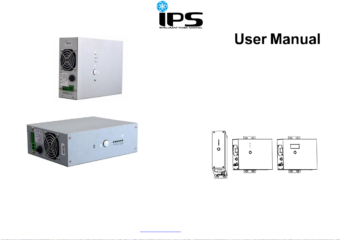
1.07.2020 www.ips-ups.eu LiftUPS-manual-EN-R1
1 Safety and General Information
The information in this document is subject to change without notice, as
standards, specifications, and designs change from time to time, please ask
for confirmation of the information given in this publication.
CAUTION
Consulting the dealer is required before using for below equipment. Its
application, configuration, management and maintenance must be specially
considered and designed.
Medical equipment which is directly related to patients’ life
Equipment which may endanger personal safety
Non-qualified electricians are forbidden to open the case due to hazard of
electrical shock. And only qualified electricians can make wiring or maintain
the UPS due to naked electrical parts at the external wiring section.
The product is not intended to be used alone for users, it is designed for
special application. Separated fire-retardant enclosure or casing for
protection is required.
The product must be grounded firmly when it is connected to the utility
power.
Output short-circuit is not allowed for the UPS in case of connecting to the
utility power.
Avoid a short circuit on positive and negative polarities of battery, otherwise
it can lead to electric shocks or a fire.
Cut off the electricity supply immediately when the UPS operates
abnormally, and contact your dealer.
~ 1 ~


 Plus Startup manual")


