iQniter Team Receiver
Installation Guide
Revision 26Sept2015
Overview
The iQniter Team Receiver is applicable to indoor group training together with iQniter Cardio
Training and it can pick up data from iQniter Dual Belts and iQniter Smart Sensors. To use iQniter
Smart Sensor belts an iQniter Team Receiver must be isnstalled.
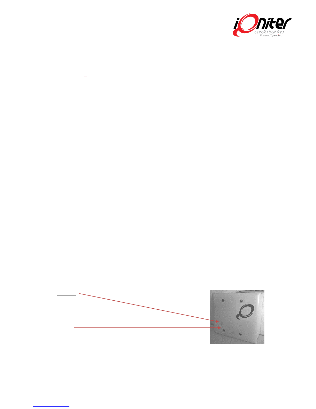
The Team Receiver must be connected via a
PoE-Adapter (Power over Ethernet) on the
same Ethernet-based Local Area Network as
the computer running iQniter Cardio
Training software is connected (i.e.
connected to the same Router). A Power
over Ethernet connector provides power
and Ethernet connectivity using one
standard network cable.
A wired connection is required
–WiFi is not applicable.
The Ethernet network must be 10 or
100Mb/s.
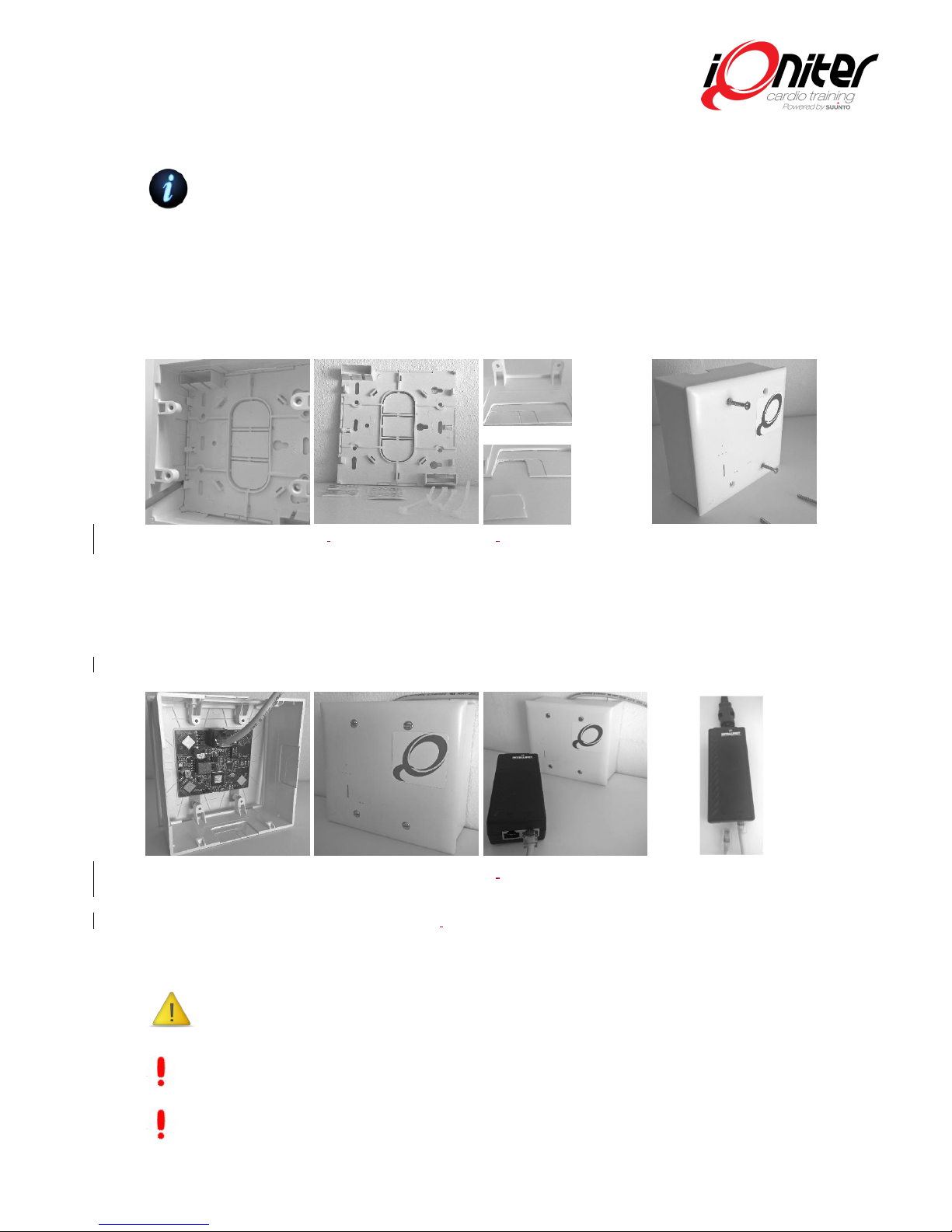
Planning/Mounting
One iQniter Team Receiver covers a room approx. 8m x 8m (24x24 ft). In order to achieve
proper functionality, the distance between the smart sensor belt and the iQniter Team
receiver shall not exceed 5-6 m. The coverage can vary, dependent on the actual conditions
in the room such as room layout, humidity, equipment in the room, number of people in the
room, workout on the floor, and others.
The Team Receiver is best utilized if it is placed as close to the center of the room as
possible, e.g. mounted on or under a drop ceilings, if available. If center room placement is
not possible, place the receiver in the front of the room (nearest to the biking instructor). If
that is insufficient, or if the size of the room exceeds the specified size, a secondary receiver
can be mounted.
The coverage of a training area can be increased, by installing more team receivers in the
same area and connect them to the same network. Using more Team Receivers also
increases the number of simultaneous participants.
iQniter Team Receivers can be installed together with Suunto Team pods. Please notice,
mixed environments of Team Pods and iQniter Team Receivers may result in areas covered
by only the Team Pod (as it has a wider range) where the Bluetooth Smart Sensors are not
received.