Iridium Stage PAR 14Z User manual

CODE 114363
STAGE PAR 14Z - Zoom
14 x 15W
Please read carefully before use
User manual
Import :
13 Rue Alfred Kastler - ZI
67850 HERRLISHEIM
FRANCE
Tel: +33 3 88 96 80 90
Fax: +33 3 88 96 48 46
www.gemarlumitec.fr

Product Overview
1 14
MENU
TFT displayer
Power out
DMX out
Power in
DMX in
knob

Mechanical Specification
2
13
356.43mm
295.07mm
226mm
276.93mm
259.93mm

Unpacking: Thank you for purchasing the AH052. Every AH052 has been tested and
shipped in perfect operating condition. Carefully check the shipping carton for damage
that may have occurred during shipping. If the carton appears to be damaged, carefully
inspect you fixture for any damage and be sure all equipment necessary to operate the
unit has arrived intact. In the event damage has been found or parts are missing, please
contact our toll free customer support number for further instructions. Please do not
return this unit to your dealer without contacting customer support first.
Introduction: The AH052 is a DMX intelligent zoom par. The AH052 can be a 3channel,
7channel, 10channel, 12channel, or 14 Channel DMX unit. The fixture can operate in
three different operating modes; show mode, sound-active or under DMX control. The
AH052 can be used as a stand unit or in a master/slave con-figuration. For best effect,
you can use fog or special effects smoke to enhance the projection of the beams.
Warning! To prevent or reduce the risk of electrical shock or fire, do not expose this unit
to rain or moisture.
Warning! This may cause severe eye damage. Avoid looking directly into the light source
at all times.
3 12
DMX Set Up
Your cables should be made with a male and female XLR connector on either
end of the cable. Also remember that DMX cable must be daisy chained and
cannot be split.
Notice: Be sure to follow figures two and three when making your own cables.
Do not use the ground lug on the XLR connector. Do not connect the cable’s
shield conductor to the ground lug or allow the shield conductor to come in
contact with the XLR’s outer casing. Grounding the shield could cause a short
circuit and erratic behavior.
Special Note: Line Termination. When longer runs of cable are used, you
may need to use a terminator on the last unit to avoid erratic behavior. A
terminator is a 110-120 ohm 1/4 watt resistor which is connected between pins
2 and 3 of a male XLR connector (DATA + and DATA -). This unit is inserted
in the female XLR connector of the last unit in your daisy chain to terminate
the line. Using a cable terminator (ADJ part number Z-DMX/T) will decrease
the possibilities of erratic behavior.
Termination reduces signal errors and
avoids signal transmission problems
and interference. It is always advisable
to connect a DMX terminal, (Resistance
120 Ohm 1/4 W) between PIN 2 (DMX-)
and PIN 3 (DMX +) of the last fixture.
DMX512 IN
3-PIN XLR
1
2
3
1
2
3
DMX +
DMX -
COMMON
DMX512 OUT
3-PIN XLR
Figure 2
Figure 3
1 Ground 1 Ground
XLR Male Socket
3 Hot
2 Cold 2 Cold
3 Hot
XLR Female Socket
Pin 3 = Data True (positive)
Pin 2 = Data Compliment (negative)
Pin 1 = Ground
1
2
3
Figure 4

Features
OPTICS
● Beam aperture: 8° to 40°
● High-effciency 42mm PMMA secondary optics
LIGHT SOURCE
● 14 *15W RGBW,quad led.
● Rated Sources life: up to 50.000 hours
● Flicker free sources Management, convenient for TV applications and all video
recorded events
DIMMER / STROBE
● Electronic dimmer, allowing perfect light adjustment from 0 to 100%
● White or colour strobe effect, from 1 to 25 flashes per second
HARDWARE FACILITIES
● Graphic LCD Display for adressing and special functions settings, with flip function
● 5 menu buttons to set the functions
● Over temperature protection
● XLR 5 pin and 3 pin connectors for DMX connections
● Choice of 5 DMX Modes (2,4,6,12,14channels)
POWER SUPPLY
● Electronic supply with active PFC
● 110 to 240 Volts – 50/60Hz
● Power 250 Watt max
COOLING SYSTEM
● Advanced ventilation cooling system based on Heatpipe technology
● Self adjusting speed fans for quiet operation
● Safety protection against temperatures excesses
HOUSING
● Body in die-cast aluminium
● Control Panel in Tempered glass
● IP20 protection index
● Size: 295(L)x226(W)x356(H)mm
11 4
Value
0—255
0—255
0—255
0—255
0—255
0—49
50—99
100—149
150—199
200—255
0—255
0—255
0—255
0—255
0—255
0 -- 7
8—10
11—20
21—30
31—40
41—50
51—60
61—70
71—80
81—90
91—100
101—110
111—120
121—255
0—255
0—255
DMX Channel
1
2
3
4
5
6
7
8
9
10
11
12
13
14
Function
Master dimmer
red
green
blue
white
Default dimmer
dimmer speed 1
dimmer speed 2
dimmer speed 3
dimmer speed 4
10 kinds of different color temperature white
strobe
zoom min to max
zoom speed slow to fast
ID number(0 - 66)
Default
program 1
program 2
program 3
program 4
program 5
program 6
program 7
program 8
program 9
program 10
Sound 1
Sound 2
sound 3
auto speed,sound sensitivity
motor reset
14 DMX Channel

On Board System
5 10
Value
0—255
0—255
0—255
0—255
0—255
0—255
0—255
0—255
DMX Channel
1
2
3
4
5
6
7
8
Function
Master dimmer
red
green
blue
white
strobe
zoom
zoom speed slow to fast
8 DMX Channel
Value
0—255
0—255
0—255
0—255
DMX Channel
1
2
3
4
Function
Hue
Staturation
Value(brightness)
zoom min to max
4 DMX Channel
Value
0—255
0—255
0—255
0—255
0—255
0—49
50—99
100—149
150—199
200—255
0—255
0—255
0—255
0 -- 7
8—10
11—20
21—30
31—40
41—50
51—60
61—70
71—80
81—90
91—100
101—110
111—120
121—255
0—255
0—255
DMX Channel
1
2
3
4
5
6
7
8
9
10
11
12
Function
Master dimmer
red
green
blue
white
Default dimmer
dimmer speed 1
dimmer speed 2
dimmer speed 3
dimmer speed 4
strobe slow to fast
zoom
zoom speed slow to fast
Default
program 1
program 2
program 3
program 4
program 5
program 6
program 7
program 8
program 9
program 10
Sound 1
Sound 2
sound 3
auto speed,sound sensitivity
motor reset
12 DMX Channel
MENU
Address
001
512
Color
001
051
Zoom
000
255
enter
Static Color
Channels Mode
Option
02
04
08
Sound
01 mode
00 speed
05 mode
99 speed
Auto
01 auto
00 speed
10 auto
31 speed
12
14
Factory Reset
Run Mode Slave
LCD Black 30s
off
60s
Dimmer All
000
255
CAL WHITE
WHITE-1
WHITE-11
Id number 001
OFF
066
Key Lock
on
off
000 Red 255 Red
000 Green 255 Green
000 Blue 255 Blue
000 White 255 White
000 Strobe 255 Strobe
000 Red 255 Red
000 Green 255 Green
000 Blue 255 Blue
000 White 255 White
Info
Working Time
Max Temp
Software Ver
000
120

Displayer introduction
①
DMX
Key lock open
temp:043
DMX Address
512
1. DMX means the light is in the DMX mode.Similarly,SLAVE means the light is in the
SLAVE mode.
2. The color of the point shows the condition of signal transmission. Green represents
the good condition, while red represents the signal is interrupted.
3. The item shows the working temperature of the light.When the working temperature
exceeds the max temperature,the color of the letters and number will change from white
to yellow.
4. This item shows the menu you selected.
5. This item shows the condition of key lock. “Key lock open” means the key lock is
open.And “Key lock off” means the key lock is close.
④
⑤
② ③
6
DMX control mode
Value
0-4
5-9
10-14
15-19
20-24
25-29
30-34
35-39
40-44
45-49
50-54
55-59
60-64
65-69
70-74
75-79
80-84
85-89
90-94
95-99
100-104
105-109
110-114
115-119
120-124
125-129
130-134
135-139
140-144
145-149
150-154
155-159
160-164
165-169
170-174
175-179
180-184
185-189
190-194
195-199
200-204
205-209
210-214
215-219
220-224
225-229
230-234
235-239
240-244
245-249
250-255
0-255
DMX Channel
1
2
Function
off
RGBW
RED
BLUE
YELLOW
CYAN
MAGENTA
WHITE
ORANGE
PINK
VIOLET
AQUA
SKY BLUE
FULL WHITE
COLL WHITE
WARM WHITE
WHITE 3200
WHITE 2500
YELLOW 2
STRAW
ORANGE
LIGHT ROSE
DARK PINK
MAGENTA
BLUE 2
MED BLUE GREEN
DARK BLUE
BRIGHT PINK
MEDIUM BLUE
GOLDEN AMBER
DEEP GOLDEN AMBER
PALE LAVENDER
APRICOT
DARK LAVENDER
CHOCOLATE
JUST BLUE
SURPRISE PINK
SCARLET
SURPRISE PEACK
FIRE
ENGLISH ROSE
MAUVE
BRIGHT BLUE
ALICE BLUE ROSCO
ROSE INDIGO ROSCO
URBAN BLUE ROSCO
COOL BLUE ROSCO
LIGHT SALMON ROSCO
MAYAN SUN ROSCO
CHERRY ROSE ROSCO
FLESH PINK ROSCO
Zoom min to max
2 DMX Channel
9

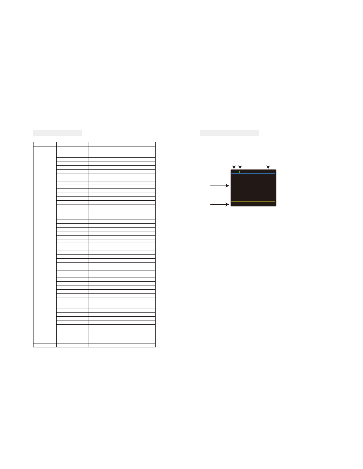
Address - DMX Address Setting via control board
1.Press “>” button ,then press the “∧” button or “∨” button until “Address” is showed.
2.Press “>” button ,“xxx” is showed,“xxx” represents the showed address.Then press “MENU” to
confirm the item.Next press the “∧” or “∨” button to select your desired address.
Run Mode - In this menu, you can select the Master/slave mode.
1.Press “>” button ,then press the “∧” button or “∨” button until “Run Mode” is showed.
2. Press “>” button again,then“slave” is showed, and Slave mode is confirmed. It will perform
following the fixture in auto mode, sound mode and chase mode.
Auto - In this menu you can select your desired Auto mode.
1.Press “>” button ,then press the “∧” button or “∨” button until “Auto” is showed.
2.Press “>” button again,then“xx auto” or “xx speed” is showed.
3.Press the “∧” button or “∨” button to find the “xx auto”.Then press “MENU” to confirm the
item.Press the “∧” button or “∨” button to select your desirable auto mode.
4.Press “<” button,then press “∧” button or “∨” button to find the “xx speed”.Press “MENU” to
confirm the item.Next press the “∧” button or “∨” button to adjust the speed of auto mode.
Sound - In this menu, you can select your desired sound mode.
1.Press “>” button ,then press the “∧” button or “∨” button until “Sound” is showed.
2.Press “>” button again,then“xx mode” or “xx speed” is showed.
3.Press the “∧” button or “∨” button to find the “xx auto”.Then press “MENU” to confirm the item.Next
press the “∧” button or “∨” button to select your desirable auto mode.
4.Press “<” button,then press “∧” button or “∨” button to find the “xx speed”.Press “MENU” to
confirm the item.Next press the “∧” button or “∨” button to adjust the speed of sound mode.
Channels mode - You can select your desired channel in this menu.
1.Press “>” button ,then press the “∧” button or “∨” button until “Channels mode” is showed.
2.Press “>” button again,then“Channel mode xx”is showed.Press “MENU” to confirm the item.Next
press the “∧” button or “∨” button to select your desirable channel mode.
Option-Set the data of fixture.
1.Press “>” button ,then press the “∧” button or “∨” button until “Option” is showed.
2.Press “>” button again,then you can find six items and adjust the data of them.
(1)color - In this menu, you can select your desired color mode.
1)Press “∧” button or “∨” button until “color” is showed, then press “>” button.
2)“xxx” representing a number between 001~051 will be showed. Press “MENU” to confirm the
item.Then press the “∧” or “∨” buttons to select your desired color.
(2)static color - In this menu, you can set your desired static color mode and strobe mode
1)Press the “∧” button or “∨” button until “static color” is showed, then press “>” button.
2)There will be five options. Press “MENU” button to confirm the option and then press “∧” or “∨”
button to set the data you desire as below.
①red(000 ~ 255)
② green(000 ~ 255)
③blue(000 ~ 255)
④ white(000 ~ 255)
⑤strobe(000 ~ 255)
(3)Dim All - In this menu,you can set the brightness of the full color
1)Press the “∧” button or “∨” button until “Dim color” is showed, then press “>” button.
2)“xxx” representing the brightness of full color between 000~255 will be showed. Press “MENU” to
confirm the item.Then press the “∧” or “∨” buttons to set the brightness.
(4)CAL WHITE - In this menu,you can set 11 kind of color temperature white by setting the data of
RED,GREEN,BLUE and WHITE.
1)Press the “∧” button or “∨” button until “Dim color” is showed, then press “>” button.
2)“xxx” representing the brightness of full color between 000~255 will be showed. Press “MENU” to
confirm the item.Then press the “∧” or “∨” buttons to set the brightness.
(5)Zoom - In this menu,you can set the zoom angle from 8°to 60°.
1)Press the “∧” button or “∨” button until “Zoom” is showed, then press “>” button.
2)“xxx” referring the zoom angle between 000~255 will be showed. Press “MENU” to confirm the
item.Then press the “∧” or “∨” buttons to set the zoom angle.
(6)ID number - In this menu,you can set the ID number.When you set the ID number,you can control
the fixture separately via DMX controller.
1)Press the “∧” button or “∨” button until “ID number” is showed, then press “>” button.
2)”OFF” or “xx” will be showed. “xx” represent the ID number between 1~66.Press “MENU” to confirm
the item.Then press the “∧” or “∨” buttons to set the ID number.
(7)Factory Reset - In this menu,you can reset the fixture.
1)Press the “∧” button or “∨” button until “Factory Reset” is showed, then press “>” button.
2)Press “MENU” to reset the fixture.
(8)LCD Black - In this menu,you can set the LCD BLACK time.
1)Press the “∧” button or “∨” button until “LCD Black” is showed, then press “>” button.
2)You will find three selections,”off”,”30s” and “60s”.Press “MENU” to confirm the item.Then press the
“∧” or “∨” buttons to select the option.
”off” represents the displayer will be on all the time.
”30s” represents the displayer will be off if the there is no operation with the fixture over 30 seconds.
”60s” represents the displayer will be off if the there is no operation with the fixture over 60 seconds.
(9)Key Lock - In this menu,you can set the key lock function.
1)Press the “∧” button or “∨” button until “Key Lock” is showed, then press “>” button.
2)You will find three selections,”off” or “on”.Press “MENU” to confirm the item.Then press the “∧” or
“∨” buttons to select the option.
“off” represents the key lock function is off.And you do not need to input the password before the
operation.
“on” represents the key lock function is open.And you need to input the password before the
operation.
Info - You can check some information of the fixture in this menu.
1.Press “>” button ,then press the “∧” button or “∨” button until “Info” is showed.
2.Press “>” button again, you will find three options,”Working time”,”Software Ver” and “Max
Temp”.Then press the “∧” button or “∨” button to check the information.
-”Working time” represents the lasting time the fixture has been working.
-”Software Ver” represents the software version of the fixture.
-“Max Temp” represents the maximum temperature.The cooling system will start working when the
operating temperature of fixture is around the maximum temperature.
78
Table of contents
Other Iridium Dj Equipment manuals