Ironton 58252 User manual

READ & SAVE THESE INSTRUCTIONS
Air-Operated 1:1 Oil Pump
With Extension Kit –4.8 GPM
Owner’s Manual
WARNING: Read carefully and understand all ASSEMBLY AND OPERATION
INSTRUCTIONS before operating. Failure to follow the safety rules and other basic safety
precautions may result in serious personal injury.
Item #58252

Page 2 of 19
Thank you very much for choosing an Ironton™product!
For future reference, please complete the owner’s record below:
Serial Number/Lot Date Code: ________________________________
Purchase Date: ____________________________________________
Save the receipt, warranty, and this manual. It is important that you read
the entire manual to become familiar with this product before you begin
using it.
This pump is designed for certain applications only. Northern Tool and
Equipment is not responsible for issues arising from modification or
improper use of this product such as an application for which it was not
designed. We strongly recommend that this product not be modified
and/or used for any application other than that for which it was designed.
For technical questions, please call 1-800-222-5381.

Page 3 of 19
Table of Contents
Intended Use..........................................................................................................................................4
Packaging Contents..............................................................................................................................4
Technical Specifications ......................................................................................................................4
Important Safety Information...............................................................................................................4
Specific Operation Warnings...............................................................................................................6
Main Parts of Pump...............................................................................................................................8
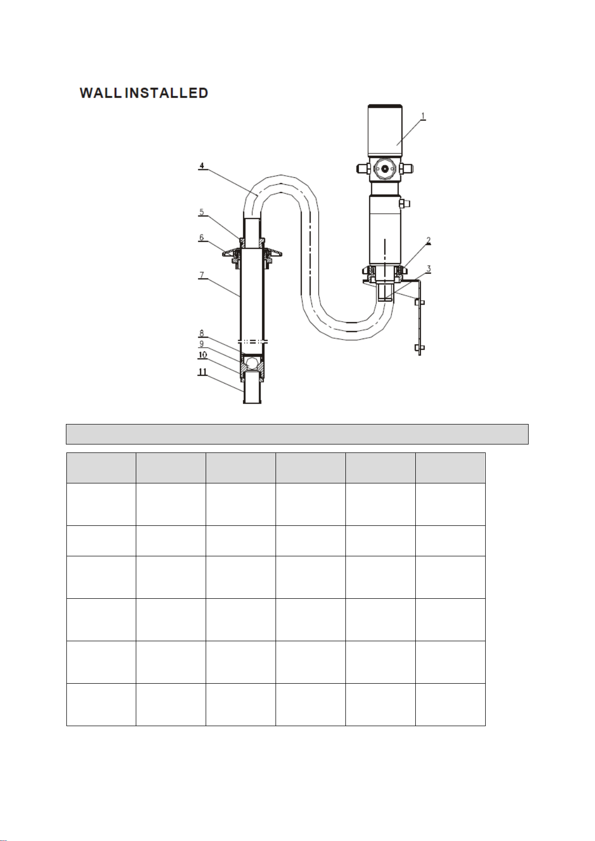
Assembly Instructions..........................................................................................................................9
Parts List..............................................................................................................................................10
Parts List..............................................................................................................................................12
Before Each Use..................................................................................................................................13
Operating Instructions........................................................................................................................13
After Each Use.....................................................................................................................................13
Maintenance ........................................................................................................................................14
Troubleshooting..................................................................................................................................14
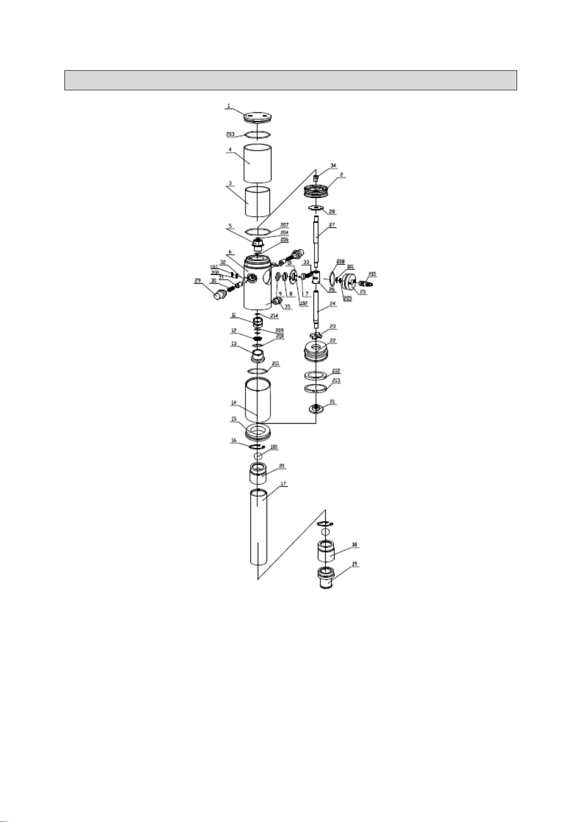
Parts Diagram......................................................................................................................................15
Parts List..............................................................................................................................................16
Replacement Parts..............................................................................................................................17
Limited Warranty.................................................................................................................................18

Page 4 of 19
Intended Use
The Ironton Air-Operated 1:1 Oil Pump can be used to transfer lubrication oil, waste oil, and antifreeze
liquids.
Packaging Contents
Part#
Description
Quantity
1701001
Air-operated pump
1
ET10000
Extension tube
1
Technical Specifications
Property
Specification
Compression ratio
1:1
Operating pressure (psi)
70-115
Max. fluid pressure (psi)
115
Air consumption (min)
@115psi/3.6CFM
Max. free flow rate (min)
4.8 gallon
Suction tube diameter
1-5/8''
Suction tube length (inch)
10-5/8''
Air inlet connection
1/4'' NPT female
Oil outlet connection
Male 1/2''
Max. viscosity oil delivered
SAE80
Temperature oil delivered
-50-122°F
Noise level (dB)
82
Important Safety Information
⚠WARNING
Read and understand all instructions. Failure to follow all instructions may result in serious injury
or property damage.
The warnings, cautions, and instructions in this manual cannot cover all possible conditions or
situations that could occur. Exercise common sense and caution when using this tool. Always be
aware of the environment and ensure that the tool is used in a safe and responsible manner.
Do not allow persons to operate or assemble the product until they have read this manual and
have developed a thorough understanding of how it works.
Do not modify this product in any way. Unauthorized modification may impair the function and/or
safety and could affect the life of the product. There are specific applications for which the product
was designed.
Use the right tool for the job. DO NOT attempt to force small equipment to do the work of larger
industrial equipment. There are certain applications for which this equipment was designed. This
product will be safer and do a better job at the capacity for which it was intended. DO NOT use
this equipment for a purpose for which it was not intended.
Industrial or commercial applications must follow OSHA requirements.

Page 5 of 19
⚠WARNING
This product may contain chemicals known to the state of California to cause cancer, birth defects,
or other reproductive harm.
Some dust created by power sanding, sawing, grinding, drilling, and other construction activities
contains chemicals known to the state of California to cause cancer, birth defects, or other
reproductive harm. Some examples of these chemicals are:
lead from lead-based paints,
crystalline silica from bricks and cement and other masonry products, and
arsenic and chromium from chemically-treated lumber.
Your risk from these exposures varies, depending on how often you do this type of work. To
reduce your exposure to these chemicals: work in a well-ventilated area, and work with approved
safety equipment, such as dust masks that are specially designed to filter out microscopic
particles.
Handling power cords on corded products may expose you to lead, a chemical known to the state
of California to cause cancer and birth defects or other reproductive harm. Wash your hands after
handling.
⚠WARNING
WORK AREA SAFETY
Inspect the work area before each use. Keep work area clean, dry, free of clutter, and well-lit.
Cluttered, wet, or dark work areas can result in injury. Using the product in confined work areas
may put you dangerously close to cutting tools and rotating parts.
Do not use the product where there is a risk of causing a fire or an explosion; e.g., in the presence
of flammable liquids, gases, or dust. The product can create sparks, which may ignite the
flammable liquids, gases, or dust.
Do not allow the product to come into contact with an electrical source. The tool is not insulated
and contact will cause electrical shock.
Keep children and bystanders away from the work area while operating the tool. Do not allow
children to handle the product.
Be aware of all power lines, electrical circuits, water pipes, and other mechanical hazards in your
work area. Some of these hazards may be hidden from your view and may cause personal injury
and/or property damage if contacted.
⚠WARNING
PERSONAL SAFETY
Stay alert, watch what you are doing, and use common sense when operating the tool. Do not use
the tool while you are tired or under the influence of drugs, alcohol, or medication. A moment of
inattention while operating the tool may result in serious personal injury.
Dress properly. Do not wear loose clothing, dangling objects, or jewelry. Keep your hair, clothing

Page 6 of 19
and gloves away from moving parts. Loose clothes, jewelry, or long hair can be caught in moving
parts. Air vents on the tool often cover moving parts and should be avoided.
Wear the proper personal protective equipment when necessary. Use ANSI Z87.1 compliant safety
goggles (not safety glasses) with side shields, or when needed, a face shield. Use a dust mask in
dusty work conditions. Also use non-skid safety shoes, hardhat, gloves, dust collection systems,
and hearing protection when appropriate. This applies to all persons in the work area.
Do not overreach. Keep proper footing and balance at all times.
Remove keys or wrenches before connecting the tool to an air supply, power supply, or turning on
the tool. A wrench or key that is left attached to a rotating part of the tool may cause personal
injury.
Secure the work with clamps or a vise instead of your hand when practical. This safety precaution
allows for proper tool operation using both hands.
⚠CAUTION
PUMP USE AND CARE
Do not force the pump. Products are safer and do a better job when used in the manner for which
they are designed. Plan your work, and use the correct product for the job.
Check for damaged parts before each use. Carefully check that the product will operate properly
and perform its intended function. Replace damaged or worn parts immediately. Never operate the
product with a damaged part.
Do not use a product with a malfunctioning switch. Any power tool that cannot be controlled with
the power switch is dangerous and must be repaired by an authorized service representative
before using.
Disconnect the power/air supply from the product and place the switch in the locked or off position
before making any adjustments, changing accessories, or storing the tool. Such preventive safety
measures reduce the risk of starting the tool accidentally.
Store the pump when it is not in use. Store it in a dry, secure place out of the reach of children.
Inspect the tool for good working condition prior to storage and before re-use.
Use only accessories that are recommended by the manufacturer for use with your product.
Accessories that may be suitable for one product may create a risk of injury when used with
another tool. Never use an accessory that has a lower operating speed or operating pressure than
the tool itself.
Keep guards in place and in working order. Never operate the product without the guards in place.
Do not leave the tool running unattended.
Specific Operation Warnings
⚠WARNING
To prevent serious injury or property damage, read and understand owner's manual before
operating.

Page 7 of 19
Wear ANSI Z87.1 compliant goggles and other protective gear while operating.
Do not exceed the maximum working air pressure of 115 PSI.
Never point the dispenser at people or animals.
Do not use the pump near open flames. Do not smoke during this operation.
When not in use, disconnect the air supply air to the pump.
Inspect before each use; check that all connections are tight and secure.
Never use if parts are damaged or broken; replace damaged or broken parts before operating.
Use only original parts when repairing the pump.
Always disconnect the air supply after use so that oil can't leak out in case one of the pump's
components should break.
The compressed air must be filtered to avoid dust and moisture into pump.
Do not use with any liquid besides the intended oil, lubricants, or antifreeze liquids. See owner's
manual for intended oil.
Disconnect air hose and relieve air pressure before servicing.
Always dispose of oil and other liquids according to local waste authority guidelines.
Not for use by or around children.

Page 8 of 19
Main Parts of Pump

Page 9 of 19
Assembly Instructions
DIRECTLY FIT PUMP INTO DRUM
•Insert the suction tube of pump into the drum and secure with ring nut. Suitable for commercial
drums with 57 diameter hole and threading 2'' BSP.
•Fit an oil delivery tube for oil outlet of the air operated pump using only high quality tubes
(normally 1/2'' or 3/4'', according to DIN-SAE norms), by means of 1/2'' BSP threading fitting.
•Oil delivery pistol: connect delivery tube with delivery pistol using suitable pipe fittings, and point
the pistol in the desired area.
•Air inlet connection is 1/4'' quick plug (or 1/4'' NPT female) in all versions.
•Compressed air connection (to be supplied by the customer) should be done using suitable
tubes.
•A pressure regulator to keep the pump's working pressure at the best possible level (max 5-8
bar) between the pump and the compressed air line.
•A cut-off switch can enable the operator to stop the pump at any given moment by cutting the air
supply off between the pump and the compressed air line.
•Switch on all switches.

Page 10 of 19
Parts List
Part#
Description
Quantity
Part#
Description
Quantity
1
Oil pump
1
7
Rigid suction
tube
1
2
Wall bracket
1
8
Spring circlip
1
3
Pump
adapter
1
9
Ball
1
4
Flexible
suction hose
1
10
Valve seat
1
5
Suction hose
adapter
1
11
Filter
1
6
Bung
adapter
1

Page 11 of 19
1. Secure the bracket to the wall using the dowels at about 1200mm height appropriate for the tank's
dimensions. Make sure that the wall is solid and thick enough for the dowels. Do not interfere with
hydraulic tubes or electric lines.
2. Secure the pump to the bracket 2.
3. Connect the flexible suction tube 4 to the pump using the clamp provided.
4. Connect the rigid suction 7 to the end of the flexible suction tube 4 using the elastic clamp provided.
5. Put the bung adapter 6 into the drum hole.
6. Put the rigid suction tube 7 into the pump and secure it in place.
•Depending on the length of the suction tube, choose the desired extension length.
•Can be decided by using the modular extension elements (see examples above).
•Remove filter and foot valve from the stub pump, screw the extension tube on (with top
connection), then screw filter and foot valve on the extension tube(foot connection End)
NOTE: 1:1 stub pump's adapter is different than others.

Page 12 of 19
CONNECT THE PUMP WITH OTHER ACCESSORIES:
Parts List
Part#
Description
1
Oil pump
2
Bung adapter
3
Oil pistol
4
Hose with fitting
5
Air hose with quick coupling
6
Drum
7 (7-1, 7-2, 7-3)
Filter, pressure regulator, and lubricator

Page 13 of 19
Before Each Use
⚠WARNING
Inspect before each use; check that all connections are tight and secure.
Never use if parts are damaged or broken; replace damaged or broken parts before operating.
Disconnect air hose and relieve air pressure before servicing.
Operating Instructions
⚠WARNING
Wear ANSI Z87.1 compliant goggles and other protective gear while operating.
Do not exceed the maximum working air pressure of 115 PSI.
Never point the dispenser at people or animals.
Do not use the pump near open flames. Do not smoke during this operation.
The compressed air must be filtered to avoid dust and moisture into pump.
Do not use with any liquid besides the intended oil, lubricants, or antifreeze liquids. See owner's
manual for intended oil.
PRESSURE RELIEF PROCEDURE
To reduce the risk of serious bodily injury, including fluid injection, splashing in the eyes or skin, or
injury from moving parts, always follow this procedure whenever you shut off the pump:
check (or service) all parts of the spray/dispensing system
clean or change the spray tips/nozzles whenever you stop spraying/dispensing.
1. Shut off the air to the pump.
2. Point the outlet of the grease gun into a container and trigger the grease gun to relieve pressure.
IMPORTANT
If you suspect that the spray tip/nozzle or hose is completely clogged, or that pressure has not been
fully relieved after following the steps above, VERY SLOWLY loosen the retaining nut or hose end
coupling and relieve pressure gradually, then loosen completely. Then clear the tip/nozzle or hose.
After Each Use
⚠WARNING
Always disconnect the air supply after use so that oil can't leak out in case one of the pump's
components should break.
•Pumps are delivered in appropriate cardboard boxes. Packaging material should be properly
disposed.

Page 14 of 19
•Handling and storage of the new pump do not require any special procedures. However after the
pump has been used, empty the used oil in the suction tube into an appropriate container. This is
done by over-turning the pump.
•The dust in compressed air can slow down and even block the motor cylinder. The following
steps may prevent this from happening:
•Add 50 grams of appropriate lubricating oil to the air inlet hole weekly; operate the pump for
several minutes after adding oil.
•Turn on the pump for several minutes until moving parts are fully lubricated.
•You may repeat the above operation if necessary.
•The above steps should be carried out on a weekly base.
•For the pumps that are attached with compressed air treatment equipment empty the water
retained in the reservoir of the filter-purger frequently.
•For the pumps that are attached with a lubricator, please pay close attention to the
lubricator's oil level and refill with SAE 20, SAE 30 or antifreeze oil for extreme conditions
when necessary.
Maintenance
•The user should perform only routine maintenance operations (filters, silencers, cleaning) in
order not to damage the unit or compromise safety.
•Contact our sales or service centers when the pump needs further maintenance.
Troubleshooting
Problem
Possible Causes
Solutions
The pump continues to operate
after the gun trigger has been
released.
1.There is an oil leak in the
circuit
2.Valve sets (part No. 21,22,23
and 212, 213) close incorrectly
due to dirt or wear.
1.Clean or recharge silencer.
2.Use clean oil.
3.Substitute damaged
elements.
Reduction of the oil delivery or
reduced pressure in the oil
delivery.
1.Silencer (210) is dirtied.
2.There is a block in the oil
circuit.
3.Ball valve ( 100) closes
incorrectly due to dirt or
wearing.
1.Clean or recharge silencer.
2.Use clean oil.
3.Substitute damaged
elements.
Air loss through the air exhaust.
1.The sliding valve (7) does not
close properly.
2.Damaged O-ring (203, 204,
206, 207).
3.Damaged piston (2).
4.Damaged washer (28).
5.Broken spring (30).
1.Disassemble and clean.
Substitute in case of damage.
2.Substitute damaged
elements.
Oil leaks through the air
exhaust.
Seal set (11) is damaged.
Substitute damaged elements.

Page 15 of 19
Parts Diagram

Page 16 of 19
Parts List
Part#
Description
Qty.
Part#
Description
Qty.
1
Air motor cover
1
27
Piston shaft
1
2
Piston
1
28
Washer
2
3
Air motor shell inside
1
29
Spring shell
2
4
Air motor shell outside
1
30
Spring
2
5
Bracket
1
31
Spring seat
2
6
Air control center
1
32
Trip shoe guide
2
7
Slider
1
33
Press piece
1
8
Gasket
1
34
Nut
1
9
Soft gasket
1
35
Outlet
1
10
Securing washer
1
100
Ball
2
11
Bracket
1
101
Small circlip
2
12
Washer
1
102
Screw
2
13
Connect tube
1
203
O-ring
2
14
Piston cover
1
204
O-ring
1
15
Cover
1
205
Silencer
2
16
Spring circlip
1
206
O-ring
1
17
Tube
1
207
O-ring
1
18
Joint
1
208
O-ring
1
19
Filter or connector
1
209
O-ring
1
20
Valve seat
1
210
O-ring
1
21
Nut
1
211
O-ring
1
22
Piston
1
212
U seal
1
23
Washer
1
213
Guiding
1
24
Middle shaft
1
214
OD seal
1
25
Air center cover
1
215
Quick coupling
1
26
Slider shell
1
216
Extension tube (ET10000)
1

Page 17 of 19
Replacement Parts
For replacement parts and technical questions, please call Customer Service at 1-800-222-5381.
Not all product components are available for replacement. The illustrations provided are a
convenient reference to the location and position of parts in the assembly sequence.
When ordering parts, the following information will be required: item description, item model
number, item serial number/item lot date code, and the replacement part reference number.
The distributor reserves the rights to make design changes and improvements to product lines
and manuals without notice.

Page 18 of 19
Limited Warranty
Northern Tool and Equipment Company, Inc. ("We'' or ''Us'') warrants to the original purchaser only
(''You'' or ''Your'') that the Ironton product purchased will be free from material defects in both
materials and workmanship, normal wear and tear excepted, for a period of 90 days date of
purchase. The foregoing warranty is valid only if the installation and use of the product is strictly in
accordance with product instructions. There are no other warranties, express or implied, including the
warranty of merchantability or fitness for a particular purpose. If the product does not comply with this
limited warranty, Your sole and exclusive remedy is that We will, at our sole option and within a
commercially reasonable time, either replace the product or product component without charge to You
or refund the purchase price (less shipping). This limited warranty is not transferable.
Limitations on the Warranty
This limited warranty does not cover: (a) normal wear and tear; (b) damage through abuse, neglect,
misuse, or as a result of any accident or in any other manner; (c) damage from misapplication,
overloading, or improper installation; (d) improper maintenance and repair; and (e) product alteration
in any manner by anyone other than Us, with the sole exception of alterations made pursuant to
product instructions and in a workmanlike manner.
Obligations of Purchaser
You must retain Your product purchase receipt to verify date of purchase and that You are the original
purchaser. To make a warranty claim, contact Us at 1-800-222-5381, identify the product by make
and model number, and follow the claim instructions that will be provided. The product and the
purchase receipt must be provided to Us in order to process Your warranty claim. Any returned
product that is replaced or refunded by Us becomes our property. You will be responsible for return
shipping costs or costs related to Your return visit to a retail store.
Remedy Limits
Product replacement or a refund of the purchase price is Your sole remedy under this limited warranty
or any other warranty related to the product. We shall not be liable for: service or labor charges or
damage to Your property incurred in removing or replacing the product; any damages, including,
without limitation, damages to tangible personal property or personal injury, related to Your improper
use, installation, or maintenance of the product or product component; or any indirect, incidental or
consequential damages of any kind for any reason.
Assumption of Risk
You acknowledge and agree that any use of the product for any purpose other than the specified
use(s) stated in the product instructions is at Your own risk.
Governing Law
This limited warranty gives You specific legal rights, and You also may have other rights which vary
from state to state. Some states do not allow limitations or exclusions on implied warranties or
incidental or consequential damages, so the above limitations may not apply to You. This limited
warranty is governed by the laws of the State of Minnesota, without regard to rules pertaining to
conflicts of law. The state courts located in Dakota County, Minnesota shall have exclusive jurisdiction
for any disputes relating to this warranty.

Page 19 of 19
Distributed by:
Northern Tool & Equipment Company, Inc.
Burnsville, Minnesota 55306
www.northerntool.com
Made in China
Table of contents
Other Ironton Water Pump manuals
Popular Water Pump manuals by other brands

Toyo
Toyo DL-1-110 Installation, operation & maintenance instructions

Pentair
Pentair STA-RITE SUPERMAX Hardware installation and user's guide

Pentair
Pentair Hydromatic H3HX Installation and service manual

IBO
IBO MAGI 2 25-40/180 manual

Pentair
Pentair STA-RITE HMS-1FL Series owner's manual

Peerless Pump
Peerless Pump LG Series instructions

EINHELL
EINHELL ROYAL TMP 255-S operating instructions

APEC PUMP
APEC PUMP SSDM-10HP Series Installation and operation manual

Fristam Pumpen
Fristam Pumpen FP Series Operator's manual

JABSCO
JABSCO 30570-0 Series manual

Johnson Pump
Johnson Pump L450 instruction manual

Pentair Jung Pumpen
Pentair Jung Pumpen DRENA-LINE Compli 310 E instruction manual