Ironton 750131 User manual

SAVE THESE INSTRUCTIONS
2" / 3" Gas Water Pump
Owner’s Manual
WARNING: Read carefully and understand all ASSEMBLY AND OPERATION
INSTRUCTIONS before operating. Failure to follow the safety rules and other basic safety
precautions may result in serious personal injury.
Items:#750131 & #750132

Page 2 of 35
Thank you very much for choosing an Ironton™product!
For future reference, please complete the owner’s record below:
Serial Number/Lot Date Code: ________________________________
Purchase Date: ____________________________________________
Save the receipt, warranty, and this manual. It is important that you read
the entire manual to become familiar with this product before you begin
using it.
This Gas Water Pump is designed for certain applications only. Northern
Tool & Equipment is not responsible for issues arising from modification
or improper use of this product such as an application for which it was
not designed. We strongly recommend that this product not be modified
and/or used for any application other than that for which it was designed.
For technical questions, please call 1-877-234-6869.

Page 3 of 35
Table of Contents
Intended Use..........................................................................................................................................4
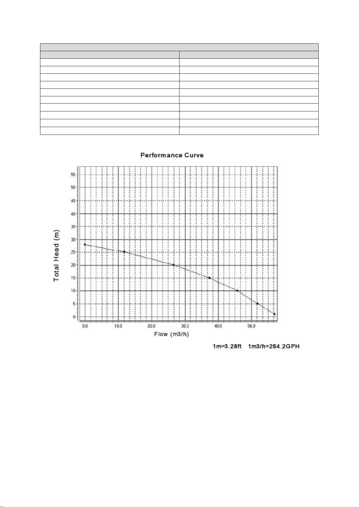
Technical Specifications......................................................................................................................4
Important Safety Information...............................................................................................................6
Specific Operation Warnings...............................................................................................................8
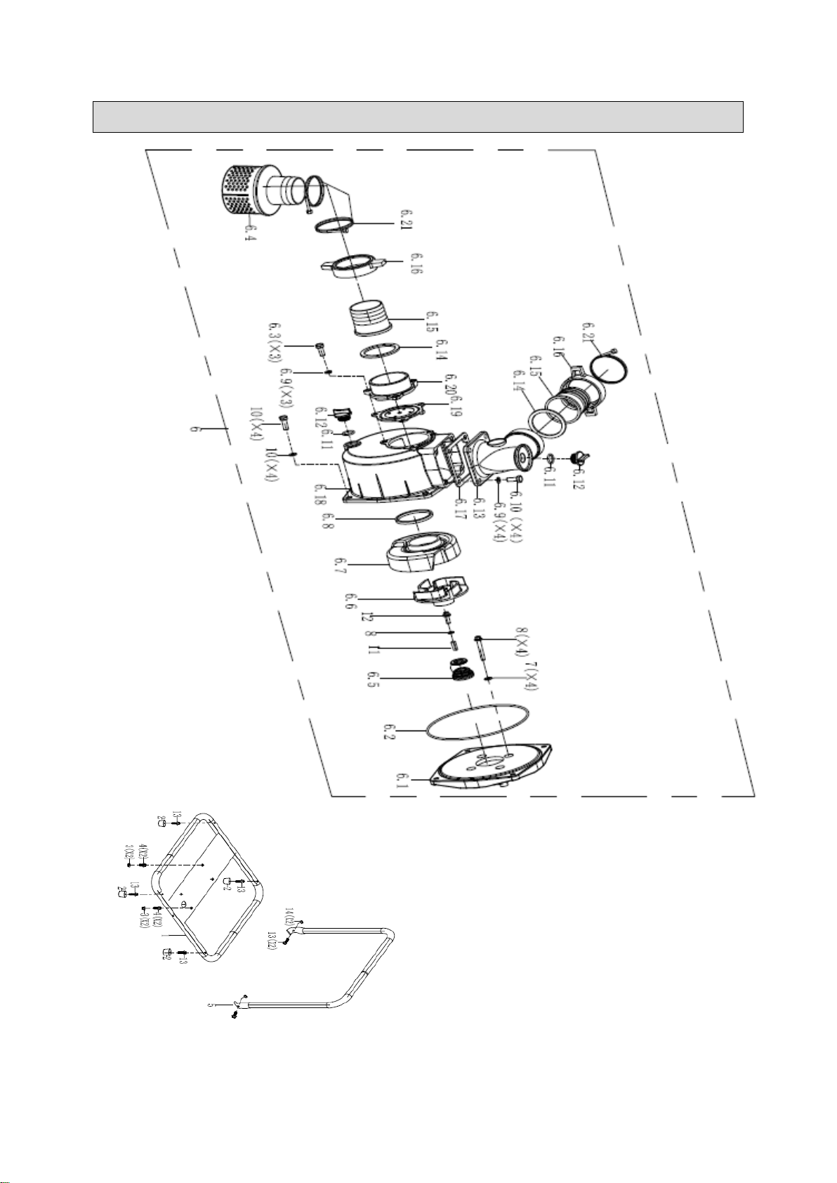
2" Pump Exploded View......................................................................................................................9
2’’ Pump Main Parts of Water Pump .................................................................................................10
3’’ Pump Main Parts of Water Pump .................................................................................................10
3″Pump Exploded View ....................................................................................................................11
Exploded View of Engine ...................................................................................................................12
Main Parts of Engine...........................................................................................................................13
Exploded View of Engine Kit..............................................................................................................14
Assembly Instructions........................................................................................................................15
Before Each Use..................................................................................................................................16
Operating Instructions........................................................................................................................19
Maintenance ........................................................................................................................................26
Storage.................................................................................................................................................30
Troubleshooting..................................................................................................................................31
Parts Diagram......................................................................................................................................32
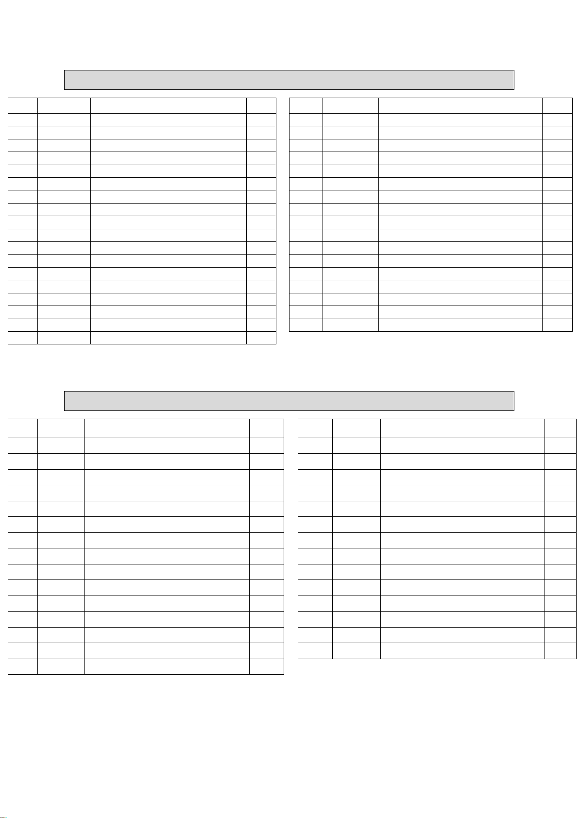
Parts List..............................................................................................................................................33
Replacement Parts..............................................................................................................................33
Limited Warranty.................................................................................................................................34

Page 4 of 35
Intended Use
The Ironton 2" and 3" Gas Water Pumps are designed with a simple structure allowing for an easy
start and reliable operation. These quiet and easy-to-use water pumps are designed to pump water
and non-corrosive liquids. The water pumps have many applications including farming irrigation,
drought-resistant irrigation, pool, flooding, pond draining, and construction sites.
Technical Specifications
2" Gas Water Pump: #750131
Property
Specification
Engine
Ironton 212cc
Suction & Discharge Size
2" NPT
Maximum Flow
7860 GPH
Maximum Suction Head
23 FT
Maximum Total Head
98 FT
Maximum Pressure
46 PSI
Passable Solid Size
5/8”
Mechanical Seal
Silicon Carbide
Overall Dimensions (L×W×H)
18"×17.5"×17"
Dry Weight
50.7 lbs.

Page 5 of 35
3" Gas Water Pump: #750132
Property
Specification
Engine
Ironton 212cc
Suction & Discharge Size
3" NPT
Maximum Flow
14,160 GPH
Maximum Suction Head
23 FT
Maximum Total Head
98 FT
Maximum Pressure
40 PSI
Passable Solid Size
5/8”
Mechanical Seal
Silicon Carbide
Overall Dimensions (L×W×H)
18" × 17.5" × 17"
Dry Weight
55.1 lbs.

Page 6 of 35
Important Safety Information
⚠WARNING
Read and understand all instructions. Failure to follow all instructions may result in serious
injury or property damage.
The warnings, cautions, and instructions in this manual cannot cover all possible conditions or
situations that could occur. Exercise common sense and caution when using this water pump.
Always be aware of the environment and ensure that the water pump is used in a safe and
responsible manner.
Do not allow persons to operate or assemble the water pump until they have read this manual
and have developed a thorough understanding of how it works.
Do not modify this water pump in any way. Unauthorized modification may impair the function
and/or safety and could affect the life of the water pump. There are specific applications for
which the water pump was designed.
Use the right tool for the job. DO NOT attempt to force small equipment to do the work of
larger industrial equipment. There are certain applications for which this equipment was
designed. It will be safer and do the job better at the capacity for which it was intended. DO
NOT use this equipment for a purpose for which it was not intended.
Industrial or commercial applications must follow OSHA requirements.
⚠WARNING
WORK AREA SAFETY
Inspect the work area before each use. Keep the work area clean, dry, free of clutter, and well
lit. Cluttered, wet, or dark work areas can result in injury. Using the water pump in confined
work areas may put you dangerously close to other cutting tools and rotating parts.
Place the water pump on a firm, level surface. If the water pump is tilted or overturned, fuel
spillage may result.
Do not allow the water pump to come into contact with an electrical source. The water pump is
not insulated and contact will cause electrical shock.
Keep children and bystanders away from the work area while operating the water pump. Do
not allow children to handle the water pump.
Be aware of all power lines, electrical circuits, water pipes, and other mechanical hazards in
your work area. Some of these hazards may be hidden from your view and may cause
personal injured or property damage if contacted.

Page 7 of 35
⚠WARNING
PERSONAL SAFETY
Stay alert, watch what you are doing, and use common sense when operating the water
pump. Do not use the water pump while you are tired or under the influence of drugs, alcohol,
or medication. A moment of inattention while operating the tool may result in serious personal
injury.
Dress properly. Do not wear loose clothing, dangling objects, or jewelry. Keep your hair,
clothing and gloves away from moving parts. Loose clothes, jewelry, or long hair can be
caught in moving parts. Air vents on the tool often cover moving parts and should be avoided.
Wear the proper personal protective equipment when necessary. Use ANSIZ87.1 compliant
safety goggles (not safety glasses) with side shields, or when needed, a face shield. Use a
dust mask in dusty work conditions. Also use non-skid safety shoes, hardhat, gloves, dust
collection systems, and hearing protection when appropriate. This applies to all persons in the
work area.
Do not overreach. Keep proper footing and balance at all times.
Remove keys or wrenches before connecting the tool to an air supply, power supply, or turning
on the tool. A wrench or key that is left attached to a rotating part of the tool may cause
personal injury.
⚠CAUTION
WATER PUMP USE AND CARE
Do not force the water pump. Products are safer and do a better job when used in the manner for
which they are designed. Plan your work, and use the correct product for the job.
Check for damaged parts before each use. Carefully check that the water pump will operate
properly and perform its intended function. Replace damaged or worn parts immediately. Never
operate the water pump with a damaged part.
Store the water pump when it is not in use. Store it in a dry, secure place out of the reach of
children. Inspect the water pump for good working condition prior to storage and before re-use.
Use only accessories that are recommended by the manufacturer for use with your water pump.
Accessories that may be suitable for one product may create a risk of injury when used with
another tool. Never use an accessory that has a lower operating speed or operating pressure than
the tool itself.

Page 8 of 35
Specific Operation Warnings
⚠WARNING
INSPECT and PREPARE the water pump before each use, as directed in this manual.
Pump clean water only. DO NOT use for salt water, brine, laundry discharge or any application
that may contain foreign materials and/or caustic chemicals.
Never pump gasoline or flammable liquids with this product.
To prevent fire hazards and to provide adequate ventilation, keep the pump at least 1 meter (3
feet) away from buildings and other equipment during operation. Do not place flammable
objects near the pump.
Know how to stop the pump quickly, and understand the operation of all controls. Never permit
anyone to operate the pump without proper instructions.
FOLLOW INSTRUCTIONS for SAFELY FUELING the engine. Gasoline is flammable and can
explode. Always use caution when handing gasoline.
Keep a fire extinguisher rated "ABC" nearby.
Refuel in a well-ventilated area with the engine stopped.
Keep refueling area clear of smoking, flames or sparks as gasoline fumes can be ignited.
Do not overfill the fuel tank. After refueling, make sure the tank cap is closed properly and
securely.
Be careful not to spill fuel when refueling. Spilled fuel or fuel vapor may ignite. If any fuel is
spilled, make sure the area is dry before starting the engine.
Never run the engine in an enclosed or confined area. Exhaust contains poisonous carbon
monoxide gas; exposure can cause loss of consciousness and may lead to death.
The muffler becomes very hot during operation and remains hot after stopping the engine. DO
NOT touch the muffler while it is hot.
Let the engine cool before storing the pump indoors.
See the Troubleshooting section of this manual before attempting any repairs. Wear personal
protective equipment such as ANSI Z87.1 compliant safety glasses and follow safety
instructions.

Page 9 of 35
2" Pump Exploded View

Page 10 of 35
2’’ Pump Main Parts of Water Pump
Ref.
Code
Description
Qty.
Ref.
Code
Description
Qty.
1
809004
SEAT, FRAME
1
6.13
7227
OUTLET
1
2
531112
RUBBER DAMPING BRACKET
4
6.14
7222
PACKING RING, WATER PUMP
2
3
90018
NUT M8
4
6.15
7208
CONNECTOR, TUBE
2
4
91348
BOLT M8X35
4
6.16
7229
NUT
2
5
804007
HANDLE, FRAME
1
6.17
7213
PACKING RING,WATER PUMP
1
6
801054
WATER PUMP ASSY
1
6.18
7204
BODY, WATER PUMP
1
6.1
7232
PUMP, COVER
1
6.19
7221
VALVE, SUCTION PORT
1
6.2
7212
PACKING RING,WATER PUMP
1
6.20
7228
INLET
1
6.3
7218
BOLT M8X20
3
6.21
7223
CLIP
2
6.4
7225
FUEL FILTER
1
7
91213
BOLT, BRITAIN M8X60
4
6.5
7209
PACKING RING,WATER PUMP
1
8
94257
FLAT WASHER
5
6.6
7230
FAN, RECOIL STARTER
1
9
91346
BOLT M8X25
4
6.7
7203
VOLUTE
1
10
94222
FLAT WASHER φ8
4
6.8
7215
PACKING RING,WATER PUMP
1
11
246509
FLAT KEY
1
6.9
7210
FLAT WASHER 8X16X1.5
7
12
91214
BOLT, BRITAIN M8X30
1
6.10
7216
BOLT M8X25
4
13
91335
BOLT M8X35
6
6.11
7219
PACKING RING, WATER PUMP
2
14
90023
LOCK NUT M6
2
6.12
7220
PLUG SCREW
2
3’’ Pump Main Parts of Water Pump
Ref.
Code
Description
Qty.
Ref.
Code
Description
Qty.
1
809001
FRAME
1
4.12
7308
BOLT M10X25
7
2
531112
RUBBER DAMPING BRACKET
4
4.13
7220
SCREW-PLUG
2
3
804007
HANDLE, FRAME
1
4.14
7314
INLET VALVE
1
4
801055
WATER PUMP ASSY
1
4.15
7320
INLET
1
4.1
7322
WATER PUMP BASE
1
5
90018
NUT M8
4
4.2
7209
PACKING RING, WATER PUMP
1
6
91348
BOLT M8X35
4
4.3
7305
PACKING RING, WATER PUMP
1
7
91335
BOLT M6X35
6
4.4
7318
OUTLET
1
8
91213
BOLT, BRITAIN M8X60
4
4.5
7302
PACKING RING,WATER PUMP
1
9
94257
FLAT WASHER 8*16*1.5
5
4.6
7230
FAN, RECOIL STARTER
1
10
91355
BOLT M10*1.25*30
4
4.7
7303
VOLUTE
1
11
94214
FLAT WASHER 10.3*20.6*1.65
4
4.8
7304
PACKING RING, WATER PUMP
1
12
246509
FLAT KEY 8*16*1.5
1
4.9
7313
BODY, WATER PUMP
1
13
91214
BOLT, BRITAIN M8X30
1
4.10
7219
PACKING RING, WATER PUMP
2
14
90023
LOCK NUT M6
2
4.11
7307
FLAT WASHER 10X19X1.5
7

Page 11 of 35
3″Pump Exploded View

Page 12 of 35
Exploded View of Engine

Page 13 of 35
Main Parts of Engine
Ref.
Code
Description
Qty.
Ref.
Code
Description
Qty.
1
240210
CRANK CASE
1
46
241901
ROD, PUSH
2
2
93027
BALL BEARING
2
47
240501
SHROUD
1
3
93507
OIL SEAL
2
48
91325
BOLT M6X12
13
4
244302
GOVERNOR ASSEMBLY
1
49
96045
PACKING, HEADCOVER
1
5
243901
SHAFT, GOVERNOR ARM
1
50
241104
COVER COMP, CYLINDER
HEAD
1
6
96804
WASHER, GOVERNOR ARM SHAFT
1
51
245702
WIND SHIELD COMP.
1
7
243902
PIN, LOCK
1
52
91330
BOLT M6X20
1
8
91816
BOLT, DRAIN PLUG
2
53
240401
FLYWHEEL ASSEMBLY
1
9
94007
WASHER, DRAIN PLUG
2
54
244601
FAN, RECOIL STARTER
1
10
240901
DOWEL PIN, CASECOVER
1
55
244503
PULLEY, STARTER
1
11
241208
PISTON
1
56
90003
NUT
1
12
241606
SCRAPER RING SET, PISTON
1
57
97514
IGNITION COIL ASSY
1
13
241503
ROD ASSEMBLY, CONNECTING
1
58
91331
BOLT M6X25
2
14
245503
PIN, PISTON
1
59
96047
PACKING, INTAKE
1
15
241301
CLIP, PISTON
2
60
242301
INSULATOR, CARBURETOR
1
16
240105
COVER ASSEMBLY, CRANKCASE
1
61
96051
PACKING, CARBURETOR
1
17
241401
OIL PLUG
1
62
94226
SPACER, CARBURETOR
1
18
245601
DIPSTICK
1
63
242701
ROD, GOVERNOR
1
19
241011
CYLINDER HEAD
1
64
244201
SPRING, THROTTLE RETURN
1
20
241704
VALVE, IN
1
65
244702-
010
RECOIL STARTER ASSEMBLY
1
21
245904
VALVE EXHAUST
1
66
240802
CLIP
1
22
241806
RETURNER, INTAKE VALVE
1
67
244403
SHROUD ASSY, UPPER
1
23
246001
SPRING, VALVE
2
68
242910
AIR CLEANER ASSEMBLY
1
24
241801
SEAT, VALVE SPRING, IN
1
69
244101
SPRING, GOVERNOR
1
25
241802
SEAT, VALVE SPRING, EX
1
70
94403
CLIP, FUEL LINE
1
26
242202
PLATE, PUSH ROD GUIDE
1
71
96054
PACKING, EXHAUST
1
27
91818
ROCKER ARM TIGHTENINIG BOLTS
2
72
243707
MUFFLER COMP
1
28
241804
ROTATOR
1
73
90011
NUT M8
2
29
91006
BOLT, STUD
2
74
94206
SPRING WASHER
2
30
91007
BOLT, STUD
2
75
243101-
010
FUEL TANK ASSEMBLY
1
31
242816
CARBURETOR ASSEMBLY
1
76
519201
FUEL TANK CAP COMP
1
32
95405
FUEL LINE
1
77
95303
CONNECTING PIPE
1
33
94408
CLIP, FUEL LINE
1
78
546606
MANUAL CHOKE ASSEMBLY
1
34
244001
GOVERNOR ARM
1
79
550605
PACKING WASHER, ONE-WAY
VALVE
1
35
91822
BOLT, GOVERNOR ARM
1
80
242101
ROCKER ARM
2
36
90016
NUT M6
3
81
95903
VENTILATION TUBE
PROTECTOR
1
37
240349
CRANKSHAFT ASSEMBLY
1
82
245205
SWITCH ASSEMBLY
1
38
246102
LIFTER, VALVE
2
83
95603
TUBE, BREATHER
1
39
96041
PACKING, CASE COVER
1
84
599601
CLIP, WIRE HARNESS
1
40
242003
CAMSHAFT ASSEMBLY
1
85
94409
CLIP, FUEL LINE
1
41
240905
PIN, DOWEL
2
86
91329
BOLT M6X16
2
42
91347
BOLT M8X30
6
87
94404
CLIP, FUEL LINE
1
43
96058
GASKET, CYLINDER HEAD
1
88
245102
SWITCH ASSEMBLY,OIL LEVEL
1
44
91359
BOLT M8X60
4
89
245104
AMPLIFIER
1
45
97108
SPARK PLUG
1

Page 14 of 35
Exploded View of Engine Kit
Kit Ref.
Kit Part
Description
Qty.
KIT1
8 9
Washer, Drain Plug
1
KIT2
10 11
Switch Assembly, Oil Level
1
KIT3
19
Oil Plug
1
KIT4
20
Dipstick
1
KIT5
47
Spark Plug
1
KIT6
50 56 57 58 67 (67.1 67.2 67.3 67.4) 68 73
Recoil Starter Assembly
1
KIT7
50 51 52
Cover Comp, Cylinder Head
1
KIT8
59 60
Ignition Coil Assembly
1
KIT9
65 66 71
Governing Spring
1
KIT10
31 33 (33.1 33.2 33.3) 61 62 63 64
Carburetor Assembly
1
KIT11
38 70 (70.1 70.2 70.3)
Air Cleaner Assembly
1
KIT12
50 72
Amplifier
1
KIT13
30 74 75 76 77
Muffler Comp
1
KIT14
34 35 38 60 78 (78.1) 79 81 82 83 84
Fuel Tank Assembly
1

Page 15 of 35
Assembly Instructions
⚠WARNING
CHECK and TEST the completed assembly as directed in this manual. Serious injury could result
from water leaks if the water pump is improperly assembled. DO NOT MODIFY the water pump’s
design.
Required Assembly Tools
Open-end wrenches:S10 and S8
Bolts:M6
Nuts:M6
Installation Steps
1. Ensure the handle mounting hole fits the base of the mounting holes.
2. Insert the bolt and screw in the nut by hand.
3. Tighten the nut with an S10 open-end wrench and then tighten the bolt with an S8 open-end
wrench.

Page 16 of 35
Before Each Use
Step One: Inspect & Repair
If the water pump has been previously used, it must be prepared BEFORE EACH SUBSEQUENT
USE.
⚠WARNING
Read instructions below carefully for inspecting and preparing the water pump. Damaged or
clogged equipment could result in leaks or uncontrolled spray.
⚠WARNING
IMPORTANT SAFETY RULES
Check oil. Before each use, check the oil level and add oil to the proper level if it's low.
Turn off engine. Turn off the engine and remove the spark plug cap before cleaning,
inspecting, or servicing the water pump.
Guards/shields. Make sure all guards and shields are replaced after servicing the water pump.
Replacement parts. If a part needs replacement, only use parts that meet the manufacturer's
specifications. Replacement parts that do not meet specifications may result in a safety
hazard or poor operation of the water pump.
1. Ensure water pump
casing is empty.
Ensure the water pump has been thoroughly flushed with fresh
water and drained from prior use.
2. Clean suction strainer.
Clean the suction strainer of any material residue.
It is important to clean the suction strainer of debris before each use,
to ensure it is not clogged.
3. Inspect & repair.
Inspect and test the water pump thoroughly.
a. Inspect fittings for cracks and leaks. Replace all damaged
fittings with original parts.
b. Check to be sure all nuts, bolts, and screws are tight.
c. Check the engine’s oil level (see engine’s owner’s manual).
d. Check for fuel leaks. Any fuel leak is a fire hazard and needs to
be repaired before starting engine.

Page 17 of 35
Step Two: Fueling
⚠WARNING
Gasoline is highly flammable and explosive. Use extreme care when handling gasoline.
A running engine is hot enough to ignite fuel. Never add fuel or remove gas cap if engine is
running or still hot.
Gasoline vapors can ignite if they collect inside an enclosure. Explosion can result.
1. Engine off / cool
The engine must be off and allowed to cool at least two minutes
before adding fuel.
2. Outdoor location
Fill fuel tank outdoors –never indoors.
3. Check engine oil level
Check engine oil level as specified in the engine manual.
4. Remove gas cap
Remove engine gas cap.
5. Add gasoline
Add gasoline through fill opening from a UL-approved container.
Important Safety Instructions:
Use approved container. NEVER pump fuel directly into engine at
gas station. Static charge can build and ignite fuel. Use a UL
approved fuel container to transfer gas to the engine.
Don’t overfill. DO NOT overfill the gas tank. Allow at least 1/2” of
empty space below the fill neck to allow for fuel expansion.
Heat / flames / sparks. Stay away from sources of heat, flame, or
sparks while adding fuel.
6. Spills / splashes
Clean up fuel spills/splashes immediately.
a. Move water pump away from spilled fuel.
b. Wipe fuel off engine and wait 5 minutes for excess fuel to
evaporate before starting engine.
c. Gas soaked rags are flammable and should be disposed of
properly.
d. If gasoline is spilled on your skin or clothes, change clothes and
wash skin immediately.
7. Replace gas cap
Replace gas cap securely before starting engine.
8. Gasoline storage
Store gasoline in a cool, dry place, tightly sealed container.

Page 18 of 35
Step Three: Attach a Suction Strainer
⚠WARNING
This pump is designed to pump water only. Never use the water pump to pump flammable liquids.
1. Attach suction strainer
A suction strainer should be attached to the suction hose. A suction
strainer has holes or slots small enough to prevent large debris from
working through and damaging the pump.
2. Keep the strainer clean
Keep the strainer clean. If possible, suspend the strainer to keep it from
working into sediment -OR-
a. Prepare a bed of large stones on which the strainer will rest.
b. Tie the strainer inside a basket or pail.
Step Four: Place the Water Pump
1. Place the water pump
near the liquid surface.
Place the water pump in a location as close to the liquid surface as
possible. This will ensure proper pump suction. All hoses must be kept
as straight as possible, avoiding sharp bends.
NOTE: 23 feet is the maximum height of a suction head.
2. Use a flexible hose.
Use at least 12” of flexible hose to make plumbing connections to the
pump body. Rigid piping may put stress on the pump, causing damage.
3. Place the unit on
secure footing.
Always be sure the unit is on secure footing. Keep the immediate pump
area free of all bystanders. If the water pump is sitting beside a pit, be
sure it is well-anchored so that it does not fall in.
4. Do not run the pump
dry.
Do not run the pump dry. Always fill the pump body with water before
starting. It is not necessary to drain the pump body after each use,
unless there is danger of freezing, settling of solids, or crystallization.
5. Fill the pump with
water.
Fill the pump with water using the priming port on the top of the pump.
(The pump self-primes only when it is first filled with priming water.)
All hoses and pipe connections must be air-tight.

Page 19 of 35
Operating Instructions
Part 1: Operating the Water Pump
⚠WARNING
Review safety information provided in this manual.
Use the priming port on the top of the pump. Completely fill the pump chamber with water
before starting the engine.
Follow these safety rules and precautions when running the water pump’s engine:
Hot muffler. If you are starting a warm engine, stay clear of the muffler. It may still be
hot enough to burn you.
Hot exhaust. Hot exhaust fumes from the engine can cause fire. Position muffler at
least 7' from combustible objects during operation.
Fire extinguisher. Have a Class B fire extinguisher available as a precautionary
measure when operating the water pump engine in dry areas.
Carbon monoxide. The running engine gives off carbon monoxide, a poisonous gas
that can kill you. You CANNOT smell it, see it, or taste it. ONLY run the water pump
engine OUTDOORS and away from air intakes. NEVER run the water pump engine
inside homes, garages, sheds, or other semi-enclosed spaces. These spaces can
trap poisonous gases, EVEN if you run a fan or open windows. If you start to feel
sick, dizzy, or weak while using the water pump, shut off the engine and get to fresh
air RIGHT AWAY. See a doctor. You may have carbon monoxide poisoning.
Before starting the engine, consult the engine’s Owner’s Manual.
Throttle control. When operating the water pump much higher than the water surface, you may
need to speed up the engine, using the throttle. When the pump is near the water surface, a
slower engine speed can be used. This will save the engine life and fuel. Consult the engine’s
Owner’s Manual for the throttle location.
Secure the flexible hose. Never allow a vehicle to run over the flexible hose. This sudden shut
off pressure can cause “hydraulic shock”. If your flexible hose must be laid across a high traffic
area, it is advised to protect the flexible hose with planking.
Keep the pump from freezing. Never allow water to freeze the pump. Freezing water can be
extremely dangerous to the pump. Always drain the water from the pump if freezing
temperatures are a factor.
Flush the pump with fresh water after each use. Some liquids being pumped may leave a solid
or sticky residue. This may shorten the life of the pump.
⚠CAUTION
HIGH ALTITUDE OPERATION
Operating at an altitude of greater than 2000 feet (610 meters) may affect your engines performance,
fuel consumption, and emissions. To remain emissions compliant and improve engine performance
at higher altitudes, a high-altitude kit is required. A high altitude kit includes a carburetor jet resized
to help correct air / fuel mixture at altitude. To order a high altitude kit or if you have additional
questions, go to www.northerntool.com or contact us at 1-877-234-6869. Please note, engines with
the high-altitude kit installed operated at lower altitudes could cause severe engine damage and
affect emissions compliance. When modified, a tag or decal should be added to the product stating
that a high-altitude kit was installed and to remind you to re-service the carburetor (re-jet) when
operating in lower altitude environments.

Page 20 of 35
Part 2: Operating the Engine
Safety Precautions
⚠WARNING
Warning
Symbol
Description
Rapid retraction of the starter cord (kickback) can jerk your hands toward the
engine faster than you can let go. Broken bones, fractures, bruises, or sprains
could result.
When starting the engine, pull the cord slowly until resistance is felt, then pull
rapidly.
Components such as blades, impellers, pulleys, sprockets, etc., must be securely
attached.
Rotating parts can contact or entangle hands, feet, hair, clothing, or accessories.
Traumatic amputation or severe laceration can result.
Operate equipment with guards in place.
Keep hands and feet away from rotating parts.
Tie up long hair and remove jewelry.
Do not wear loose-fitting clothing, dangling drawstrings, or items that could
become caught.
Engines give off carbon monoxide, an odorless, colorless, poisonous gas.
Start and run the engine outdoors.
Do not start or run the engine in enclosed areas, even if doors or windows are
open.
Running engines produce heat. Engine parts, especially mufflers, become
extremely hot. Severe thermal burns can occur on contact. Combustible debris,
like leaves, grass, and brush, can catch fire.
Allow the muffler, the engine cylinder, and the fins to cool before touching.
Remove accumulated debris from the muffler and cylinder areas.
Install and maintain in working order a spark arrester before using equipment on
forest-covered, grass-covered, brush-covered unimproved land. The state of
California requires this. Other states may have similar laws. Federal laws apply on
federal land.
Starting an engine creates sparks. Sparking can ignite nearby flammable gases.
Explosion and fire could result.
If there is natural or an LP gas leakage in the area, do not start the engine.
Do not use pressurized starting fluids because vapors are flammable.
This manual suits for next models
1
Table of contents
Other Ironton Water Pump manuals
Popular Water Pump manuals by other brands

GORMAN-RUPP
GORMAN-RUPP FILL-RITE FR700V Series Installation and operation manual

salmson
salmson SHS Installation and starting instructions

Edson
Edson 165AL-30 Operations & parts manual

SMC Networks
SMC Networks PAF3413 Operation manual

Eaton
Eaton 620 Service manual

KNF
KNF NF5 Operating and installation instructions