7
Placement tips:
- The sensor should be mounted in an area free of shadows or reections of sunlight by
nearby coverings and objects.
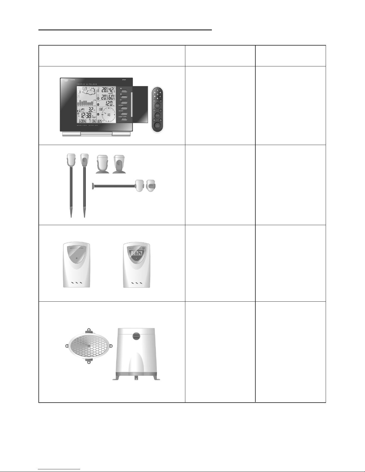
Setting up the Thermo-Hygro Sensor(s)
1. Open the latch at the base of the thermo-hygro sensor.
2. Set the channel with a slide switch.
3. Insert two 2 x UM-3 or “AA” size 1.5V batteries.
4. Use a pin to press the “RESET” key which is in the battery compartment of thermo-hygro
sensors.
5. Replace the latch and mount unit at desired location.
Placement tips:
- The thermo-hygro sensor should be in an area with free air circulation and sheltered
from direct sunlight and other extreme weather conditions. Place the unit in a shaded
area, such as under a roof.
- Use the wall mount and ttings provided if mounting the unit on a vertical surface.
- Avoid placing the sensor near sources of heat such as chimneys.
- Avoid any areas which collect and radiate heat in the sun, such as metal, brick or
concrete structures, paving, patios and decks.
- Ideally, place the sensor above natural surfaces such as a grassy lawn.
- The international standard height for measurements of air temperature is at 1.25m (4 ft)
above ground level.
Setting up the Rain Sensor
1. Unlock the funnel-shaped top of the rain sensor by turning both knobs on the sides of
the rain sensor in an anti-clockwise direction.
2. Lift the top off the base and insert two 2 x UM-3 or “AA” size 1.5V batteries into the
battery holder.
3. Replace the lid and secure into place by turning the knobs clockwise.
4. Place the rain sensor in a location such that precipitation can fall directly into the sensor,
ideally 2-3 ft above the ground.
It may be secured into place by using the four screws provided.
5. The sensor must be accurately level for optimum performance. To check if the sensor
is level, remove the lid and check if the ball bearing inside is at the midpoint of the
leveler. Additionally, a bubble level or carpenter’s level may be used.
6. Attach the protective screen onto the top of the lid. The screen will prevent any debris
entering the sensor.
Placement tips:
- The rain sensor should be placed in an open area away from walls, fences, trees and
other coverings which may either reduce the amount of rainfall into the sensor, deect
the entry of wind-blown rain, or create extra precipitation runoff. Trees and rooftops may
also be sources of pollen and debris.
- To avoid rain shadow effects, place the sensor at a horizontal distance corresponding to
two to four times the height of any nearby obstruction.
- It is important that rain excess can ow freely away from the sensor. Make sure that
water does not collect at the base of the unit.
- The rainfall measurement mechanism utilizes a magnet, hence do not place any
magnetic objects around the proximity of the sensor.