D
4. Sicherheitshinweise
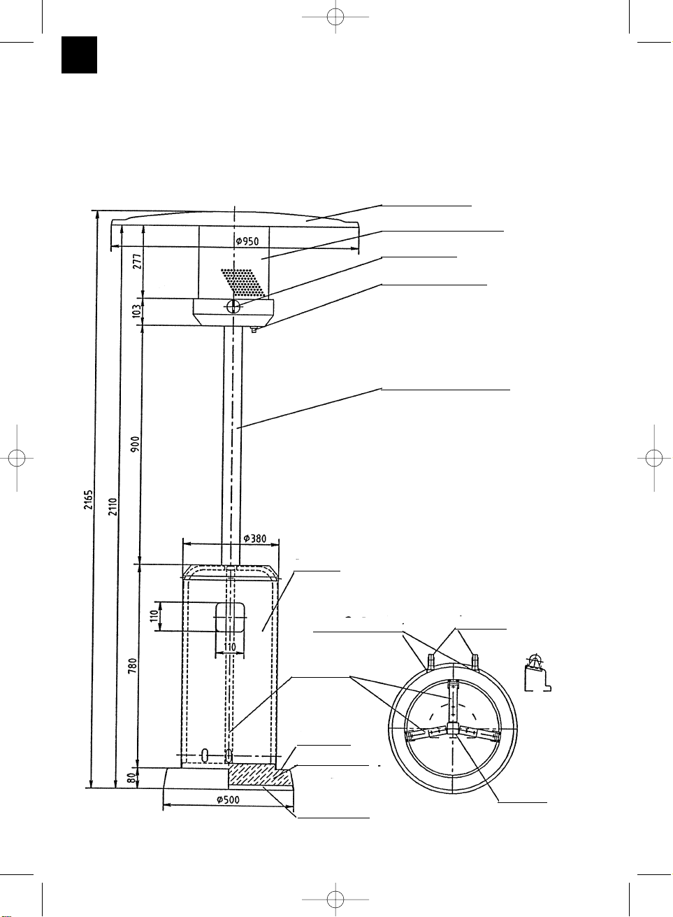
Party-Strahler auf eine ebene, nicht oder nur
schwach geneigte Fläche stellen (max. 5°).
Den Fuß unbedingt zur Verbesserung der
Standsicherheit mit Sand füllen.
Achtung - Gerät nur für beaufsichtigten Betrieb.
Reflektor und Lochblech bei Betrieb nicht
berühren - Verbrennungsgefahr !
Es muß ein sicherer Abstand zu brennbaren
Gegenständen während des Betriebes
eingehalten werden.
An dem Party-Strahler dürfen keine
Gegenstände befestigt werden.
Das Gerät darf nur im Freien verwendet werden.
Der Party-Strahler dient ausschließlich zu
Heizzwecken.
Bei starkem Wind ist es ratsam den Fuß
zusätzlich zu beschweren, bzw. am Boden zu
befestigen oder das Gerät an einem sicheren Ort
zu verwahren.
Bei längerem Nichtgebrauch den Lochblech- und
Aufsatzkorpus mit Folie abdecken, um das
Eindringen
von Staub und Insekten zu vermeiden.
Ein Standortwechsel ist nur mit abgeschaltetem
Party-Strahler durchzuführen
Kontrollieren Sie den ordnungsgemäßen
Zustand und das Vorhandensein der Dichtung
am Flaschen-
ventil. Keine zusätzlichen Dichtungen
verwenden.
Im Falle einer Störung ist das Absperrventil der
Gasflasche sofort zu schließen.
Der Party-Strahler darf nur über einen
zwischengeschalteten Druckregler mit einem
zulässigen Aus-
gangsdruck, siehe Geräteschild und werkseitige
Einstellung, betrieben werden.
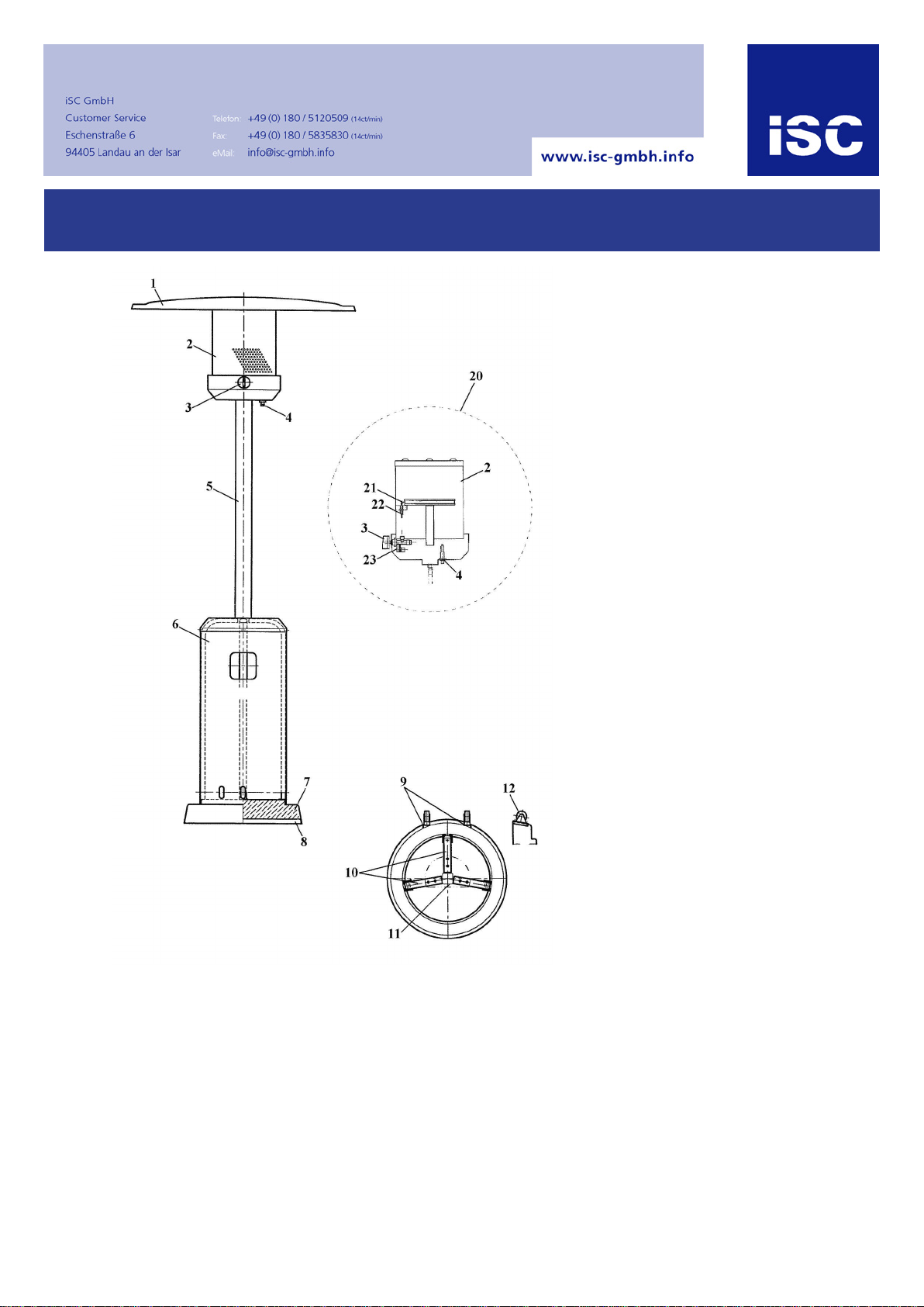
5. Anschluß an die Gasflasche
(5 bzw. 11 kg)
Zum Anschluß des Gerätes sind folgende Teile
erforderlich:
handelsübliche Gasflasche
fest eingestellter, DVGW-anerkannter
Druckregler, max. 1,5 kg/h passend zur
verwendeten Gasflasche
Betriebsdruck siehe werkseitige Einstellung
DVGW-anerkannte Schlauchleitung
ausreichender Länge, die eine knickfreie
Montage erlaubt
(Bestandteil des Gerätes)
DVGW-anerkanntes Lecksuchspray oder
schaumbildendes Mittel
6. Bedienungsanleitung
6.1 Inbetriebnahme
Vor der Inbetriebnahme des Gerätes ist eine
Dichtheitsprüfung an allen Verbindungsstellen mittels
Lecksuchspray oder einem schaumbildenden Mittel
durchzuführen. Keine offene Flamme verwenden.
„Die Prüfung darf nicht bei Betrieb erfolgen.“
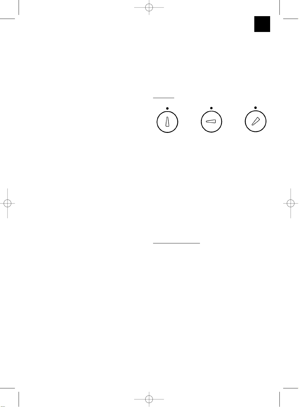
Zündung
Gasflaschenventil öffnen.
Den Hahnknebel von der „Geschlossen“-Stellung um
90° nach links drehen. Danach den Knebel
eindrücken und den Brenner durch Betätigung des
Piezozünders zünden.
Nach der Zündung muß der Knebel noch ca. 10
Sekunden eingedrückt bleiben, bis der Brenner in
Betrieb bleibt.
Bei Erlöschen der Flamme darf ein zweiter
Zündversuch frühestens nach zwei Minuten erfolgen.
Je nach Bedarf kann der Knebel vom kleinen
Flammenbild (Kleinbrand) auf großes Flammenbild
(Vollbrand) gedreht werden. Zwischen diesen beiden
Stellungen ist die Wärmeleistung stufenlos
einstellbar.
Außerbetriebnahme
Bei Außerbetriebnahme des Gerätes den Knebel in
„Geschlossen“-Stellung bringen und
Gasflaschenventil schließen
7.Reinigung / Pflege / Reparatur
7.1 Reinigung / Pflege
Der Party-Strahler kann mit allen handelsüblichen
nichtscheuernden und nichtbrennbaren Flüssigkeiten
gereinigt werden.
Das Gerät muß bei der Reinigung außer Betrieb und
ausreichend abgekühlt sein.
Achtung! Gerät nicht mit Druckwasser (Abspritzen
mit dem Wasserschlauch, Dampfstrahl oder
Hochdruck) reinigen !
7.2 Reparatur
Reparaturen und Wartungsarbeiten am Party-
Strahler dürfen nur von einem zugelassenen
Gasinstallateur ausgeführt werden.
7
GESCHLOSSEN Vollbrand Kleinbrand
Anleitung PS 1001_ 10-spr 25.10.2001 11:00 Uhr Seite 7