8-
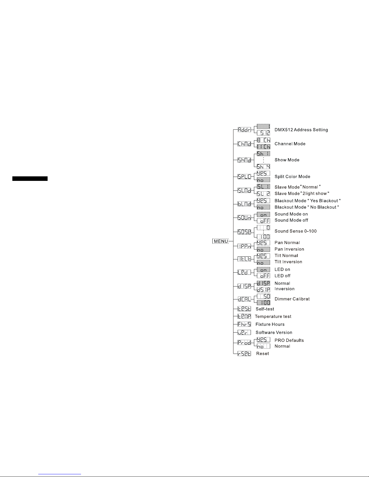
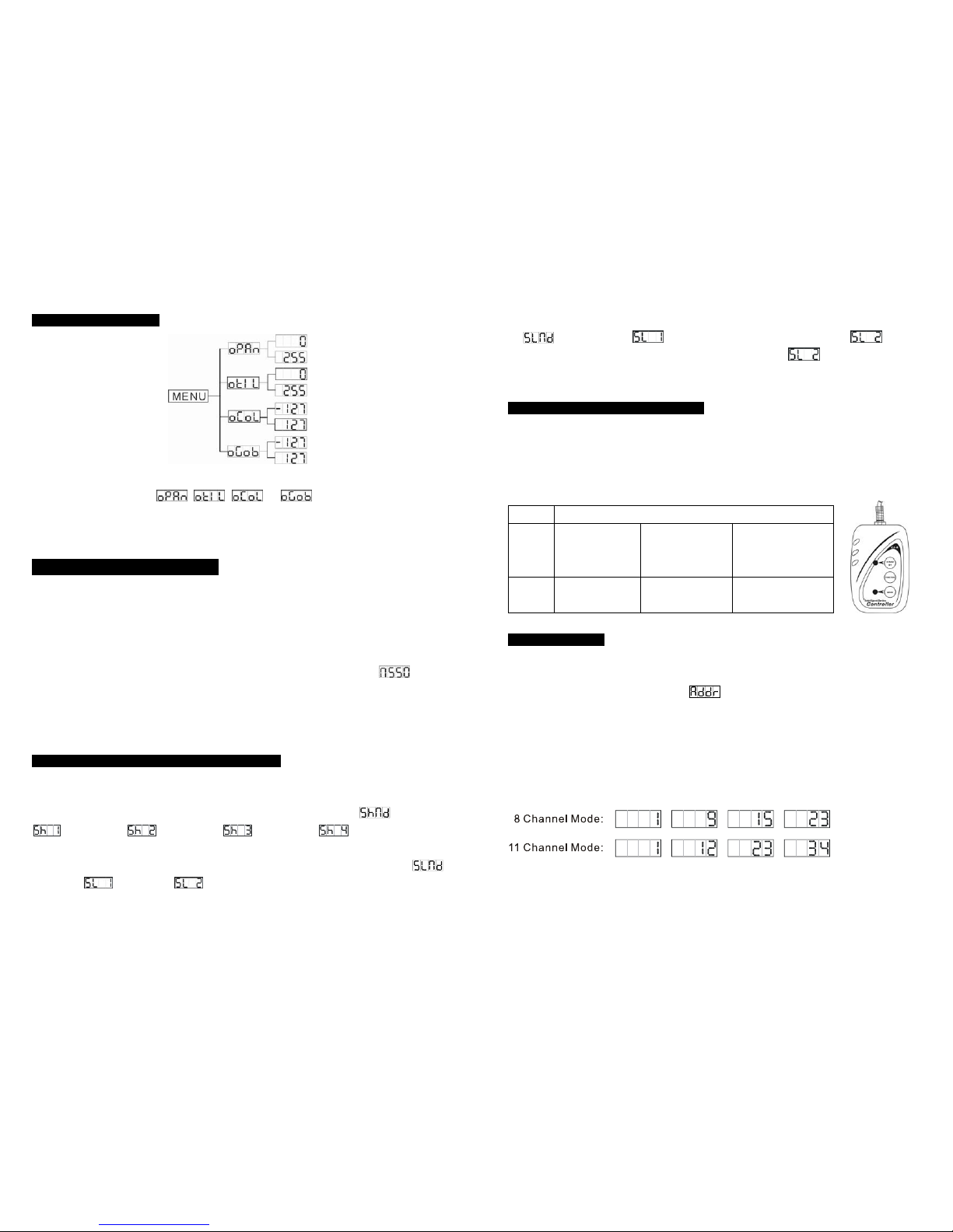
DMX 512Address Setting
Press the MENU button to show on the display. Press the ENTER button and the
display will blink. Use the DOWN and UP buttons to change the DMX512 address. Once the
address has been selected, press the ENTER button to setup, to go back to the functions
without any change press the MENU button again. Hold and press the MENU button about
one second or wait for one minute to exit the menu mode.
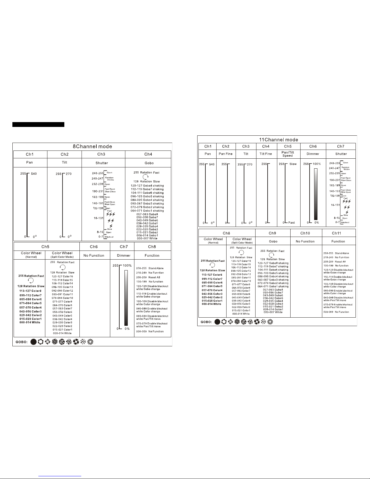
Channel Mode
Press the MENU button to show on the display. Press the ENTER button and the
display will blink. Use the DOWN and UP button to select the (8 channel mode) or
(11 channel mode) mode. Once the mode has been selected, press the ENTER
button to setup, to go back to the functions without any change press the MENU button
again. Hold and press the MENU button about one second or wait for one minute to exit the
menu mode.
ShowMode
Press the MENU button to show on the display. Press the ENTER button and the
display will blink. Use the DOWN and UP button to select the (show 1) or
(show 2) or (show 3) or (show 4) mode. Once the mode has been selected,
press the ENTER button to setup, to go back to the functions without any change press the
MENU button again. Hold and press the MENU button about one second or wait for one
minute to exit the menu mode.
Split Color Mode
Press the MENU button to show on the display. Press the ENTER button and the
display will blink. Use the DOWN and UP button to select the (Split color mode) or
(normal) mode. Once the mode has been selected, press the ENTER button to
setup, to go back to the functions without any change press the MENU button again. Hold
and press the MENU button about one second or wait for one minute to exit the menu mode.
Slave Mode
Press the MENU button to show on the display. Press the ENTER button and the
display will blink. Use the DOWN and UP button to select the (normal) or
9-
(2 light show) mode. Once the mode has been selected, press the ENTER button to setup,
to go back to the functions without any change press the MENU button again. Hold and
press the MENU button about one second or wait for one minute to exit the menu mode.
Blackout Mode
Press the MENU button to show on the display. Press the ENTER button and the
display will blink. Use the DOWN and UP button to select the (yes blackout) or
(no blackout) mode. Once the mode has been selected, press the ENTER button to
setup, to go back to the functions without any change press the MENU button again. Hold
and press the MENU button about one second or wait for one minute to exit the menu mode.
Sound Mode
Press the MENU button to show on the display. Press the ENTER button and the
display will blink. Use the DOWN and UP button to select the (sound on) or
(sound off) mode. Once the mode has been selected, press the ENTER button to setup, to
go back to the functions without any change press the MENU button again. Hold and press
the MENU button about one second or wait for one minute to exit the menu mode.
Sound Mode
Press the MENU button to show on the display. Press the ENTER button and the
display will blink. Use the DOWN and UP button to select the … mode.
Once the mode has been selected, press the ENTER button to setup, to go back to the
functions without any change press the MENU button again. Hold and press the MENU
button about one second or wait for one minute to exit the menu mode.
Pan Inversion
Press the MENU button to show on the display. Press the ENTER button and the
display will blink. Use the DOWN and UP button to select the (normal) or
(pan inversion) mode. Once the mode has been selected, press the ENTER button to setup,
to go back to the functions without any change press the MENU button again. Hold and
press the MENU button about one second or wait for one minute to exit the menu mode.
Tilt Inversion
Press the MENU button to show on the display. Press the ENTER button and the