Isotech SYNERGY Installation manual

SYNERGY®Color Operator Console
Operations Manual
Weapons Control System, 2 Lane
PLC Software: Vi26: 10/24/13
Display Software: Vi19 10/24/13
Isotec Security Inc., 1130 West 124th Avenue, Westminster, CO • 720-545-2816 • IsotecSecurity.com

page 210/24/13
Operator Console Operation Manual
This document describes the screen images and controls available in Isotec Security’s
SYNERGY Touchscreen Consoles, as supplied with various Safety Entrance products. This
document reflects features supported in the iH8 revision of the console software.
The use of the touch screen is quite intuitive and flows in a very predictable fashion. Each
screen, and the various controls that show on that screen, are described in the following
sections.
MAIN SCREEN
In normal operation, the Main screen will be displayed as follows:
The outline on the screen represents the Safety Entrance structure and doors, with the exterior
(unprotected) part of the building shown on the left, and the entry lane shown on the bottom.
Indicators are provided that show doors either open or closed and locked or unlocked (via
colors), and whether a particular area is occupied. Also shown is a clock showing the current
time. The screen in the image above is shown with Entry and Exit lock switches hidden.
In addition to the controls related to status and operation of the Safety Entrance, the main
screen also has controls for the Video system and the Intercom system.
The Video button at the top right of the screen will switch the display to the Video
viewing screen, which allows viewing the inspection tray camera.

page 310/24/13
The Intercom button shown below the B door symbol allows communication with the
intercom station in the B zone. If a call is active, this symbol will turn yellow. If a
person at the intercom remote station presses the call button, the symbol will flash
yellow for 10 seconds or until the call request is acknowledged by pressing the
symbol. An “incoming call” voice message is also played when the symbol is flashing.
Volume for both intercom and voice messages is controlled by the small knob on the lower
panel to the right of the speaker.
Normal Entry Sequence:
The static (unoccupied) condition is when all four doors (A-D) are closed, and the B and D doors
locked (top view in the flow chart below). Note that when a door is locked and bonded, the door
symbol will change from green to red. The person entering will open the ‘A’ door (which shows
open and yellow), then will move into the ‘A’ zone (nearest the outer door). A footprint symbol
appears showing the occupancy of the ‘A’ zone (middle view). As the ‘A’ door closes and the
person moves toward the ‘B’ zone, he/she is evaluated by the metal detector in the center of the
lane. If no metal is detected, the ‘A’ door will lock, the ‘B’ door will unlock (lower view), and the
user may open the ‘B’ door to enter the facility. This sequence normally happens as a smooth,
continuous transition, with minimum delays. Note that the ‘B’ door will not unlock until the ‘A’
door is closed and locked, the ‘A’ zone is unoccupied, and there is no metal detector alarm.
An exit sequence (not illustrated) works in the same fashion, and symbols are the same as the
entry lane. Operationally, once the ‘C’ zone is occupied and the ‘C’ door closes, the ‘C’ door will
lock and will not unlock until the exit lane is completely unoccupied and the ‘D’ door has re-
closed. The ‘D’ door will unlock once the ‘D’ zone is occupied and the ‘C’ door is closed and
locked .
A B
D C
E
X
T
E
R
I
O
R
E
X
T
E
R
I
O
R
I
N
T
E
R
I
O
R

page 410/24/13
ALERT SCREENS
There are six possible alert screens that may appear depending on various conditions that are
described below. This chart shows the various screen examples. These indicators will appear
as a popup at various locations on the screen. In the case of the bottom four alarms, the most
critical one will appear on the screen first.

page 510/24/13
Metal Detected Alarm:
This popup will occur when someone moves from the ‘A’ zone to the ‘B’ zone carrying a metal
object. The Alarm popup has a Red background, and is accompanied by a “metal detected”
voice message at the operator console, as well as a flashing red light inside the ‘B’ door.
The operator then instructs the person (via the intercom) to place all metal objects in the
inspection tray and walk back to the ‘A’ zone. If desired, the “metal detected” voice message
can be muted with the “Mute” button. After inspecting the contents of the tray using the
overhead video camera, the operator will press the Metal Detected button, resetting the alarm.
The person can then move through the metal detector again to demonstrate that no additional
metal is being carried. If no additional metal is detected, the ‘B’ door will now unlock as above.
Optionally, the system can be configured to automatically reset when the entering person
moves back to the ‘A’ zone. This option provides less security, but eliminates the need to have
the operator manually reset the alarm. Please see your Isotec Dealer if you would like to
consider this configuration.
A box to at the lower left of the popup area in the Metal Alarm mode may show the words
“Possible Tamper”. In normal operation, this will never be displayed; however if tampering with
the electronics cabinet is detected, this symbol will be shown and a voice message will play. If
this occurs, contact your dealer for troubleshooting. The alarm cannot be reset if tampering is
detected.
If the system is equipped with a left object detection system and an object is detected in the B
zone, the Possible Left Object symbol will show on the screen. The object should be removed
before resetting the metal alarm.
If the Auto Attendant function is enabled, the tones and operator actions will be different. Refer
to the section below describing the Auto Attendant operation.

page 610/24/13
System Override:
The System Override Popup is displayed whenever one of the following events occur:
Operator depresses the System Override button on the screen (this button will flash if it
is pressed);
The rear panel Override Switch is moved to the “up” position (which displays a red light
on the rear panel adjacent to that switch)
The Key Switch on the Safety Entrance has been turned to the off position (red led);
The building Fire Alarm system opens the contact across the fire alarm input.
During System Override, all doors are unlocked, and the status displays on the Safety Entrance
alternate red and green. System Override displays the popup screen shown above on the
operator console, accompanied by a “system unsecure” voice message. System Override can
only be cancelled by resetting whatever caused it to occur (release the Emergency Release
button, turn the Key Switch back on (green led), or end the Fire Alarm).
There is a Mute button located on the popup. Pressing this button will disable the alarm
message. Once the Override is cleared, the Mute is automatically reset, and the message will
be heard again the next time Override occurs
Similarly, there is a button to disable the alternating red/green lights in the Safety Entrance.
This is typically used when the System Override button is used to disable the system during
non-business hours, and the user does not want the lights flashing at that time. As with the
Mute button, this disabling is canceled when the Override is cleared.
Note that during System Override, the metal detection is disabled.

page 710/24/13
Timeout Alarms
A Timeout Popup is displayed on the screen if any zone in the Safety Entrance is occupied for
more than 45 seconds (default value) or any door is held open for more than 15 seconds
(default value). These default values are adjustable by your Isotec Dealer. Either or both of
these alarms can be disabled, or can be set to a different time, from the Dealer setup screens.
A Timeout alarm can be cleared, by pressing the alarm symbol, without clearing the underlying
cause, at which point a new timeout countdown will start if the Safety Entrance is still occupied.
A timeout alarm does not disable any normal system operations. It is accompanied by an
appropriate voice message alert.
Assistance Request
This popup is displayed if someone outside the Safety Entrance presses the Assistance
Request button. It may be cancelled by pressing the Help Requested symbol on the popup,
or will clear automatically after a 10 second timeout. The Assistance Request popup is
accompanied by a “Help requested” voice message.

page 810/24/13
The Emergency Egress popup is only shown if the system is equipped with emergency egress
button(s) on the exit lane.
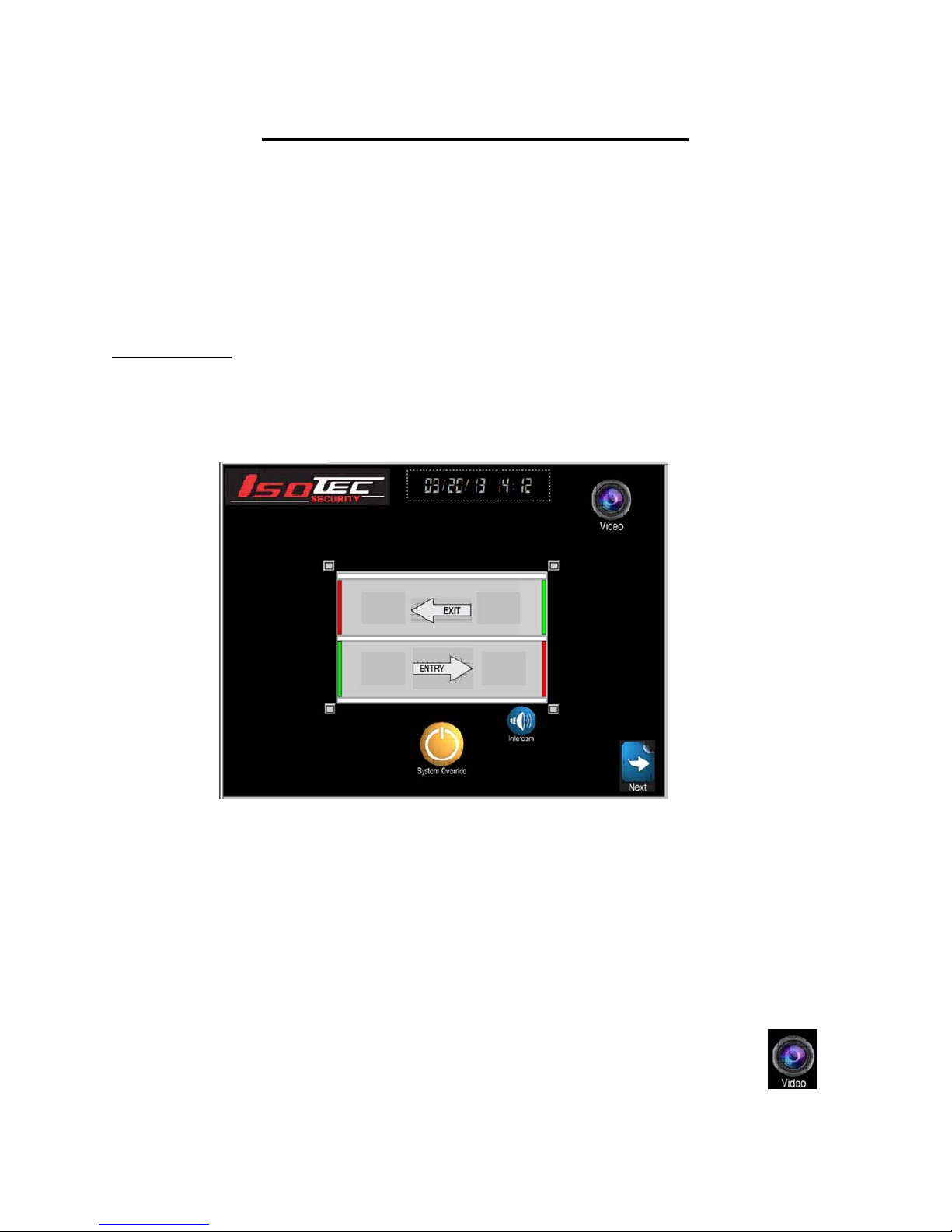
In normal operation, if the ‘D’ door is operating properly, the ‘D’ door will unlock when someone
approaches that door from the inside, and the ‘C” door is closed. If there is some failure in the
system and the ‘D’ door does not unlock correctly, or if there is a need to unlock the whole lane
in an emergency, a person can press an Emergency Egress button. This will start a 15 second
(30 second optional) time out, during which a horn will beep in that lane. After the delay, the ‘C’
and ‘D’ doors will be unlocked and the horn will sound continuously.
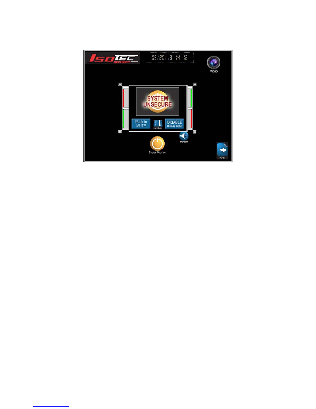
Once the Emergency Egress button is pressed, a popup screen appears, showing the release
has been initiated, accompanied by a “emergency egress initiated” voice message’. A bar
graph on the right is also displayed showing the time remaining. At the end of the 15 second
time, the screen shows “Emergency Release ACTIVATED” (while the doors are actually
unlocked). At this point, a CLEAR button appears on the screen,, and the voice message
changes to “emergency egress activated”. The doors will remain unlocked until reset by the
system console (default configuration) or optionally can be set to relock automatically 8 seconds
after being opened and then closed. This latter configuration may not be approved by local
code authorities.
Once the release countdown is initiated, it cannot be cancelled by the Safety Entrance occupant
or the console operator until the door unlocks. Please contact your Isotec Dealer for more
information on Emergency Egress configuration options.
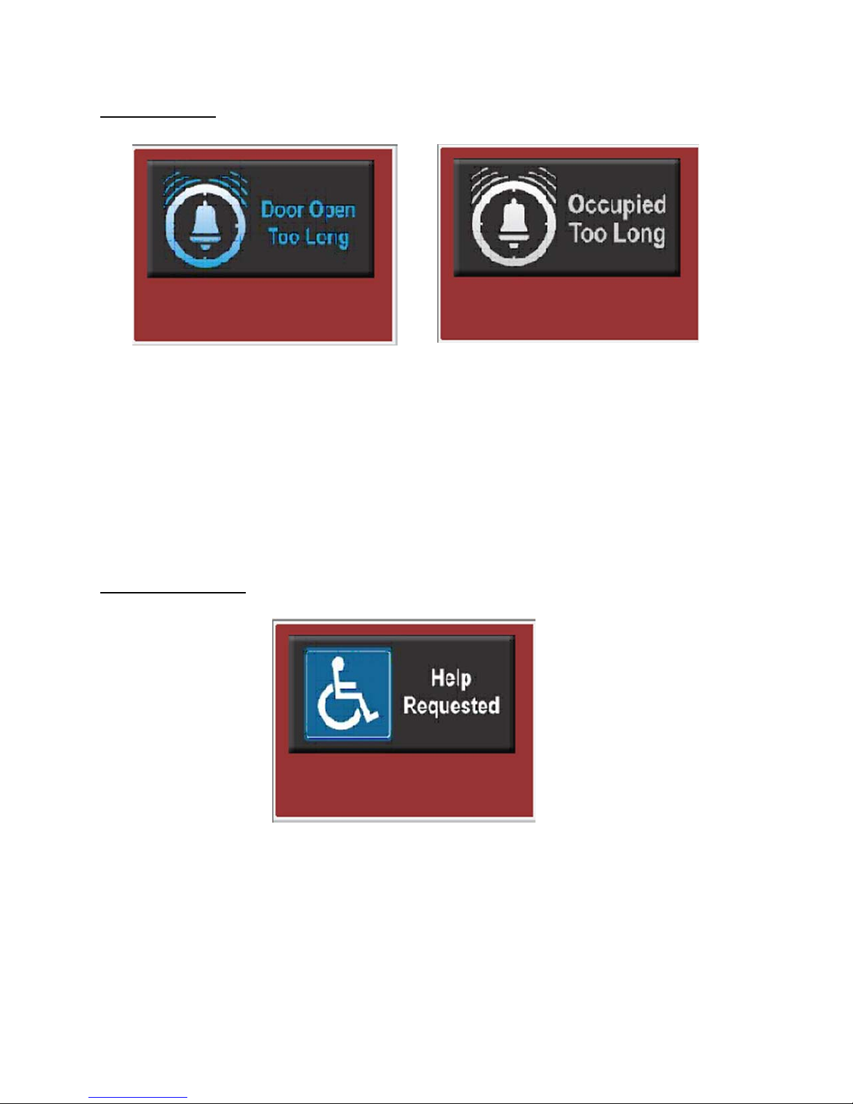
Alternate Timed Emergency Release: The System can also be configured with a timed
release function, separate from the function invoked with the emergency egress pushbuttons
described above. There are two features to this time release. If this mode is enabled, if either
the C or D door is held open for the Release Time (Default = 15 seconds), both doors in the exit
lane unlock. Secondly, if someone becomes disabled in the C or D zone, and/or the D door
does not unlock for some reason when the exit lane is occupied, after the Release Time, the D
door will unlock automatically.
When this occurs, the exit breached symbol will appear on the screen.

page 910/24/13
Menu Screen:
The Menu screen is reached by pressing the Next button on the main screen. This
Screen provides access to diagnostic and information screens via the red and white
buttons on the left. These screens provide useful information and setup features.
Additionally, this screen provides access to the dealer configuration screens which are
used by your dealer for initial setup, via a special password. From each of these
screens, you can return to the Main screen by pressing the ”home” symbol at the lower right of
the screen.
(note: On systems with the dual operator console option, the “Slave” console does not have
access to the troubleshooting and setup screens. The right arrow on the Slave console only
allows setting the clock.)
The Diagnostic screen is reached by pressing the ‘Diagnostic’ button on the Options screen.
This shows a graphic similar to the main screen. In addition, boxes indicate the state of the
door position, occupancy, and door bonded sensors. This can be useful in troubleshooting a
failed component or installation problem. Also shown is a rectangle on the top right side of the
screen. If the system inputs are all in the condition they should be for the static mode, the

page 10 10/24/13
words Static OK shows in the rectangle. All of the following conditions are required for static
ok to be displayed:
All doors closed;
B & D doors locked and bonded;
A & C doors unlocked and unbonded;
no occupancy in any zone;
no metal detector alarm.
The Input/Output List screen is reached by the ‘Input/Output’ button on the Control screen.
This brings up a display of all the inputs and outputs of the PLC, for troubleshooting purposes.
Yellow squares surround the symbols for the signals that should be on when the system is in
the “static ok” configuration (unoccupied, all doors closed and locked properly). If any of these
signals are off, or other ones are on, something is not operating correctly.
The Self Test screen allows the operator to start a self test process by simply pressing one
button on the screen and having someone walk through the entry and exit lanes. Pressing the
“Press to start Self Test” button clears all the prior values. As the person walks through the
Safety Entrance, each device is tested, and if it is operational, the small square for that device
turns dark. After a complete entry and exit, all the squares should show “on”. If any one does
not turn on, that device has not cycled. They should illuminate in order, so the first one that
does not illuminate is the likely failed component. The example below shows the screen at the
start of self test.
In order to test the metal detector, a Manufacturer’s Test Piece should be carried during the
entry test. The operator can clear the metal alarm from this same screen to complete the entry
cycle.

page 11 10/24/13
The Statistics screen allows viewing various statistics associated with the system. Pressing
the button brings up a table showing various event statistics:
Entry Attempts is the number of times the A door has been opened (ie, someone entered
the Safety Entrance from the exterior door). This is a different value than the Customer
Counter on the Setup screen, which is the number of times the B door has been opened.
Metal Detector Valid Alarms is the number of times the metal detector has gone off when
someone is inside the Safety Entrance.
MD Alarm per Entry Attempt is the percentage of the entries that resulted in a metal
detector alarm. This may be helpful in determining the sensitivity settings on the metal
detector.
MD Bypass Resets is the number of times that the operator clears a metal detector alarm
when the B zone is occupied, letting someone in who may be unscreened.

page 12 10/24/13
MD Bypass per Valid Alarm is the percentage of the Metal Detector Alarms that are
cleared by an MD Bypass event.
Completed Entries is the total number of persons that passed through the B door. This
counter is separate from the Customer Counter on the Setup screen and is reset along with
the other statistics.
Aborted Entries is the number of times someone entered the entry lane, and turned around
and left via the A door. This event would most likely occur when setting off the metal
detector alarm, and the person leaving to remove additional metal objects.
Metal Detector False Alarms is the count of times the metal detector went off when no one
is in the Safety Entrance. A high value here is generally an indication of external noise that
should be corrected.
Exit Lockdowns is the number of times that the Exit Lock function is invoked by the
operator or via the remote switches.
A button is provided on this screen to allow resetting the counters to zero. This button can be
enabled or disabled from the dealer setup section. Default is enabled.
The system can count up to approximately 30,000 events. In order to not display erroneous
values, the system will “auto-reset” when the entry attempts counter gets to 30,000.
The Setup Screen deals with the customer counter and alert, the entry alert tone, and setting
the clock:
The Console can be configured to play a voice message for the operator when the A door is
opened. The button on the top left of this screen (shown as “OFF” in the view above) can be
toggled on and off to enable or disable this message. The factory default is off.

page 13 10/24/13
The Customer Counter totals the number of times the B door has been opened. This gives an
approximation of the number of people that have passed thru the system. This counter can be
reset by pressing the green Reset button located adjacent to the counter indication. This count
IS maintained when power is removed from the system.
The system can alert the operator when a specified number of entries has occurred. Toggling
the Alert ON/OFF button enables this alert (the default is OFF). The trigger value can be set by
touching the alert value box, and entering the new value on the keyboard that will appear. Hit
the ENT key on the keyboard to set the new value into memory. When the counter reaches this
value, the “Customer Counter” symbol will flash on the main screen
The Time and Date can be set by pressing the “Set Clock” button. That brings up the following
screen:
Set the time and date by touching each field and entering the correct value. When done, press
the SET CLOCK button to save the settings. Press the Previous button to return to the Setup
screen or the Home button to go to the main screen.

page 14 10/24/13
Alarm Log brings up a screen that provides a historical record of various alarm indications and
when they occurred.
The Alarms that might be displayed, and their meanings, are as follows:
Metal Detected – the metal detector has detected a metal object when the Safety Entrance is
occupied.
Metal Detect – False Alarm – the metal detector has detected a metal object when the Safety
Entrance is not occupied.
Possible Tamper – shows if the system thinks that the electronics cabinet has been opened.
Timeout – either the Safety Entrance was occupied too long or a door has been held open too
long. The times for these timeouts can be set by your dealer.
Override – whenever one of the override devices has been tripped. (see System Override
above for those conditions.)
Emergency Release – the emergency release button has been pressed.
Power Up – time when power was applied to the system
Exit Trap Invoked – the Exit Lock button has been pressed
MD Bypassed – an operator has cleared a metal alarm when someone was in the B zone. The
normal procedure is to have the person move back to the A zone before clearing the alarm, so
they can be rescreened after putting items in the inspection tray.
The Alarm History screen has Focus UP and Focus DOWN buttons for scrolling up and down
the history log. These move the focus about one page at a time. Hold the button to scroll
multiple pates. To erase the Alarm History, press and Delete All button and the alarm list will
clear.
The Alarm History screen stores the most recent 1000 events, even if the power to the system
is removed.

page 15 10/24/13
The Revisions screen displays the revision of the software in the Touchscreen and also
displays the revision of the software loaded in the system processor.
The Support info screen displays contact information for service on your system. Your dealer’s
name and phone will appear where the characters are in this view:
The User Guide screen provides access to short explanations of the more common topics
encountered in operating the system. Contents will vary based on the current software.

page 16 10/24/13
LOCK BUTTONS
Isotec Safety Entrances have the option to be configured so that doors can be locked from the
Touchscreen, overriding the normal Safety Entrance logic. This locking may or may not be
allowed by local code authorities; your Isotec Dealer can assist you with determining if these
features are allowed, & if so, can enable those desired.
The functions available are Lock A door, Lock B door, and Exit Lane Lock If these features are
enabled by your dealer, the screen lock buttons will be displayed as shown below:
Switches hidden Switches displayed
The A Door Normal and B Door Normal buttons each lock their respective door when touched.
Door Normal indicates that the door locks work per the normal Safety Entrance logic; Door
Locked is displayed when the button is touched to lock the door. The following shows the A
door locked with the lower left button:
Note that the A door button shows LOCKED, and also that the A door symbol (the red vertical
bar) is displayed as flashing red.

page 17 10/24/13
The Exit NORMAL button on the top left may be used to detain someone in the exit lane. If this
button is depressed, then the C door will remain unlocked until someone enters the exit lane.
Once C door closes with the exit lane occupied, the C door will lock, and the D door will remain
locked, rather than unlocking as it would in a normal exit. Thus the occupant of the lane is
trapped until the Exit Lock button is toggled back to Normal. Once the Exit Lock is turned off,
the occupant can leave via the D door.
In addition to locking the Exit lane, the system can be configured to also lock either the A door,
the B door, or both, when the Exit Locked button is engaged. Your dealer can configure this
option for you.
B Door Momentary Unlock
Your system has the option to allow the operator to unlock the B door temporarily to allow
someone inside the building to enter the Safety Entrance at that door to assist someone, such
as a person in a wheelchair who cannot move far enough through the metal detector to avoid a
metal alarm. It is NOT to be used to let someone exit from the Safety Entrance via the B door
after setting off the metal alarm – that should be done by clearing the metal alarm. The default
for this function is “off”, so if it is required in your application, please ask your dealer to enable
the function. When enabled, “hold to unlock” will appear below the B Lock button.
The B Door Unlock is performed by pressing and holding the B Door Lock button. After two
seconds, the B door will unlock (and the A door will lock if it is closed) and will remain unlocked
as long as the button is held.
The “B door unlock” can also be operated via the right button on a wireless remote (see below).
This button must be held for 6 seconds before the door will unlock, and will stay unlocked as
long as the button is held.
AUTOMATED ATTENDANT
The system can be configured for Automated Attendant operation by your dealer. Certain
portions of the Automated Attendant function are optional. When the Automated Attendant is in
operation, a symbol will appear on the console screen:

page 18 10/24/13
The Automated Attendant feature allows reduced operator workload. It should only be used in
conjunction with the voice prompt option alerting the occupant as to what action to take in the
case of a metal alarm, and it is recommended that the High Zone Left Object Detection option
also be installed, and no inspection tray be installed.
The operation is as follows: If an individual enters the entry lane and triggers the metal
detector, they will hear a voice prompt that instructs them to turn around, exit the Safety
Entrance, remove all metal objects, and reenter the Safety Entrance. Once the individual exits
the Safety Entrance, both doors are closed, and no occupancy is detected, and no objects are
detected in the high zone, the metal alarm is automatically cleared, allowing the next person to
enter. The console operator will see the metal detector alarm popup, but will not hear any voice
message during this sequence.
If the person remains in the B zone after the voice prompt for 10 seconds, the “metal detected”
voice message will pay at the console, alerting the operator that action is required. At this point,
the operator would need to contact the occupant via intercom to provide further instructions or
resolve the situation.
If an “left object” (i.e., a weapon) is detected in the B zone after a person exits the Safety
Entrance via the A door, after a few seconds, the “metal detected” voice message will play on
the console, alerting the operator that something has been left behind and action is required.
The Metal Alarm will not be reset automatically if a left object has been detected. When a left
object is detected during a metal alarm, a warning text box is displayed adjacent to the Metal
Detector Alarm symbol. Note that the Left object detector will not only detect objects on the
floor, but will also trigger if someone is still standing in the B zone. :
After the Safety Entrance is empty and a Left Object alarm occurs, the operator should manually
lock the A door via the A Door button, evaluate what is left in the Safety Entrance via the video
monitor or direct inspection, and remove the offending object before clearing the metal alarm.
As part of the Automated Attendant feature set, a second voice prompt in the lane is available.
If someone enters the Safety Entrance and remains in the A zone, or two people enter and one
remains in the A zone, after 5 seconds, a voice prompt is played telling the person to move
forward through the metal detector. This eliminates the requirement for an operator to direct
people in this situation.

page 19 10/24/13
CREDENTIAL RESET:
As a further method to reduce operator workload, the Safety Entrance also has the capability to
be outfitted with a Credential system (card reader/pin device and/or biometric reader) that can
be configured to allow a person entering the Safety Entrance who set off the metal detector to
clear the metal alarm by presenting their credentials. These credentials would of course only be
given to “trusted” individuals who the facility wishes to enter the facility with metal objects. The
operation requires no action on the part of the system operator; the entrant simply presents the
credential after passing through the metal detector (if an alarm is triggered). The Alarm resets
and the person can continue through the Safety Entrance. This system is often utilized in
conjunction with the Automated Attendant feature to reduce operator interaction to almost zero.
REMOTE TRANSMITTERS:
Isotec offers the options of either single or two button remote control transmitters, which allow
certain functions to be implemented without having to go to the operator console. This might be
useful for other officers in the bank to operate the system in parallel with the console operator.
The single button remote, or the top left button on a multi-button remote, is used to clear the
metal detector alarm. Depressing that button and holding it for 1 second (to prevent inadvertent
presses) ends the alarm immediately. At that point, the Safety Entrance will work normally (for
example, the B door will unlock if all the normal logic conditions are met)
On the two button remote option, the right button function is programmable by your Isotec
Dealer. The functions available are:
A door Lock
B door Lock
Entry Lock (both A and B doors locked)
Exit Lock (same operation as the Exit lock on the Touchscreen)
Release All (same function as depressing the Override button on the console – releases
all doors.)
In the case of the first four functions, the operation of the button is “alternate action” – in other
words, the first press turns on the function (hold for 1 second – a flashing red light indicates the
remote has triggered and you can release the button), and the second press turns off the
function. Note that if one transmitter is used to turn on the function, either that transmitter or
another transmitter can be used to turn off the function. There is an indicator on the Operator
Console that shows when the function is toggled “ON” as shown by the words “Remote On” on
the screen example below. Note also the purple rectangle next to the A door lock symbol,
indicating that is what the remote is controlling:

page 20 10/24/13
In the case of the Release All function, the remote button acts as a momentary push button (it
does not latch as the other functions do). In order to preclude inadvertent operation of the
Release All function, this button must be held depressed for 1.5 seconds before the doors
release. This button must then be held down to keep the doors released. Holding this button
will only hold the doors open for about 10 seconds and is only intended for a temporary door
release. If the system needs to be overridden for a longer time period, use the OVERRIDE
button on the Operator Console.
Similar to the “B” door touchscreen button, if the “Unlock B” remote function is selected, and the
“B unlocks after hold 6 seconds” setting is enabled, the right button on the remote can be used
to unlock the B door as well. When using the remote to unlock the B door, the button must be
depressed for 6 seconds, to avoid inadvertent unlocking. The door will remain unlocked as long
as the button continues to be held. Note that the red indicator light on the remote will stop
flashing after about 3 seconds of pressing. The default for the “unlock after hold-remote” is
“Disabled”.
Third Remote Button: Isotec systems, starting with software rev Hr2, can have a third remote
button. This button is hard wired as a “B Door Lock” function. This allows the 2nd button to be
used for another function besides B Door Lock. This button is Alternate Action as well – press
to lock, press to unlock (as with the other buttons, you must hold it on for 1 second). Remote
On will also show when this button is active, as will the small diamond by the B door..
EXTERNAL CARD INPUTS:
The system has the capability to be wired to one or more external contacts that can be used to
unlock various doors or lanes. This would be wired by your dealer as part of the installation.
These inputs could be used for external card readers or as a remote “override” capability. The
inputs available are:
A door Card in
B door Card in
Exit Lane Unlock in
Table of contents